EP2383437A2 - In Schaufel integrierter Wärmtauscher in einem Gasturbinentriebwerk - Google Patents
In Schaufel integrierter Wärmtauscher in einem Gasturbinentriebwerk Download PDFInfo
- Publication number
- EP2383437A2 EP2383437A2 EP11164073A EP11164073A EP2383437A2 EP 2383437 A2 EP2383437 A2 EP 2383437A2 EP 11164073 A EP11164073 A EP 11164073A EP 11164073 A EP11164073 A EP 11164073A EP 2383437 A2 EP2383437 A2 EP 2383437A2
- Authority
- EP
- European Patent Office
- Prior art keywords
- airfoil
- plenum
- cover
- jumper tube
- pressure
- Prior art date
- Legal status (The legal status is an assumption and is not a legal conclusion. Google has not performed a legal analysis and makes no representation as to the accuracy of the status listed.)
- Withdrawn
Links
- 239000012530 fluid Substances 0.000 claims abstract description 28
- 230000002093 peripheral effect Effects 0.000 claims description 6
- 239000007787 solid Substances 0.000 claims description 6
- WYTGDNHDOZPMIW-RCBQFDQVSA-N alstonine Natural products C1=CC2=C3C=CC=CC3=NC2=C2N1C[C@H]1[C@H](C)OC=C(C(=O)OC)[C@H]1C2 WYTGDNHDOZPMIW-RCBQFDQVSA-N 0.000 claims description 5
- 238000004891 communication Methods 0.000 claims description 3
- 239000003921 oil Substances 0.000 description 18
- 239000007789 gas Substances 0.000 description 11
- 238000001816 cooling Methods 0.000 description 9
- 238000010276 construction Methods 0.000 description 4
- 239000000463 material Substances 0.000 description 4
- 239000000446 fuel Substances 0.000 description 3
- 238000012546 transfer Methods 0.000 description 3
- 229910045601 alloy Inorganic materials 0.000 description 2
- 239000000956 alloy Substances 0.000 description 2
- 230000008901 benefit Effects 0.000 description 2
- 239000000567 combustion gas Substances 0.000 description 2
- 238000013461 design Methods 0.000 description 2
- 238000005461 lubrication Methods 0.000 description 2
- 238000000034 method Methods 0.000 description 2
- 230000001052 transient effect Effects 0.000 description 2
- 238000003466 welding Methods 0.000 description 2
- 229910001008 7075 aluminium alloy Inorganic materials 0.000 description 1
- 229910000838 Al alloy Inorganic materials 0.000 description 1
- 230000009471 action Effects 0.000 description 1
- 230000001154 acute effect Effects 0.000 description 1
- 238000004026 adhesive bonding Methods 0.000 description 1
- 239000010724 circulating oil Substances 0.000 description 1
- 230000008878 coupling Effects 0.000 description 1
- 238000010168 coupling process Methods 0.000 description 1
- 238000005859 coupling reaction Methods 0.000 description 1
- 239000000945 filler Substances 0.000 description 1
- 238000005242 forging Methods 0.000 description 1
- 230000004927 fusion Effects 0.000 description 1
- 230000006872 improvement Effects 0.000 description 1
- 230000001050 lubricating effect Effects 0.000 description 1
- 239000010687 lubricating oil Substances 0.000 description 1
- 238000003754 machining Methods 0.000 description 1
- 238000012986 modification Methods 0.000 description 1
- 230000004048 modification Effects 0.000 description 1
- 238000004806 packaging method and process Methods 0.000 description 1
- 230000035515 penetration Effects 0.000 description 1
- 238000003756 stirring Methods 0.000 description 1
Images



Classifications
-
- F—MECHANICAL ENGINEERING; LIGHTING; HEATING; WEAPONS; BLASTING
- F01—MACHINES OR ENGINES IN GENERAL; ENGINE PLANTS IN GENERAL; STEAM ENGINES
- F01D—NON-POSITIVE DISPLACEMENT MACHINES OR ENGINES, e.g. STEAM TURBINES
- F01D5/00—Blades; Blade-carrying members; Heating, heat-insulating, cooling or antivibration means on the blades or the members
- F01D5/12—Blades
- F01D5/14—Form or construction
- F01D5/18—Hollow blades, i.e. blades with cooling or heating channels or cavities; Heating, heat-insulating or cooling means on blades
-
- F—MECHANICAL ENGINEERING; LIGHTING; HEATING; WEAPONS; BLASTING
- F01—MACHINES OR ENGINES IN GENERAL; ENGINE PLANTS IN GENERAL; STEAM ENGINES
- F01D—NON-POSITIVE DISPLACEMENT MACHINES OR ENGINES, e.g. STEAM TURBINES
- F01D25/00—Component parts, details, or accessories, not provided for in, or of interest apart from, other groups
- F01D25/08—Cooling; Heating; Heat-insulation
- F01D25/12—Cooling
-
- F—MECHANICAL ENGINEERING; LIGHTING; HEATING; WEAPONS; BLASTING
- F01—MACHINES OR ENGINES IN GENERAL; ENGINE PLANTS IN GENERAL; STEAM ENGINES
- F01D—NON-POSITIVE DISPLACEMENT MACHINES OR ENGINES, e.g. STEAM TURBINES
- F01D25/00—Component parts, details, or accessories, not provided for in, or of interest apart from, other groups
- F01D25/18—Lubricating arrangements
-
- F—MECHANICAL ENGINEERING; LIGHTING; HEATING; WEAPONS; BLASTING
- F01—MACHINES OR ENGINES IN GENERAL; ENGINE PLANTS IN GENERAL; STEAM ENGINES
- F01D—NON-POSITIVE DISPLACEMENT MACHINES OR ENGINES, e.g. STEAM TURBINES
- F01D9/00—Stators
- F01D9/02—Nozzles; Nozzle boxes; Stator blades; Guide conduits, e.g. individual nozzles
- F01D9/04—Nozzles; Nozzle boxes; Stator blades; Guide conduits, e.g. individual nozzles forming ring or sector
- F01D9/041—Nozzles; Nozzle boxes; Stator blades; Guide conduits, e.g. individual nozzles forming ring or sector using blades
-
- F—MECHANICAL ENGINEERING; LIGHTING; HEATING; WEAPONS; BLASTING
- F01—MACHINES OR ENGINES IN GENERAL; ENGINE PLANTS IN GENERAL; STEAM ENGINES
- F01D—NON-POSITIVE DISPLACEMENT MACHINES OR ENGINES, e.g. STEAM TURBINES
- F01D9/00—Stators
- F01D9/06—Fluid supply conduits to nozzles or the like
- F01D9/065—Fluid supply or removal conduits traversing the working fluid flow, e.g. for lubrication-, cooling-, or sealing fluids
-
- F—MECHANICAL ENGINEERING; LIGHTING; HEATING; WEAPONS; BLASTING
- F02—COMBUSTION ENGINES; HOT-GAS OR COMBUSTION-PRODUCT ENGINE PLANTS
- F02K—JET-PROPULSION PLANTS
- F02K3/00—Plants including a gas turbine driving a compressor or a ducted fan
- F02K3/02—Plants including a gas turbine driving a compressor or a ducted fan in which part of the working fluid by-passes the turbine and combustion chamber
- F02K3/04—Plants including a gas turbine driving a compressor or a ducted fan in which part of the working fluid by-passes the turbine and combustion chamber the plant including ducted fans, i.e. fans with high volume, low pressure outputs, for augmenting the jet thrust, e.g. of double-flow type
- F02K3/06—Plants including a gas turbine driving a compressor or a ducted fan in which part of the working fluid by-passes the turbine and combustion chamber the plant including ducted fans, i.e. fans with high volume, low pressure outputs, for augmenting the jet thrust, e.g. of double-flow type with front fan
-
- F—MECHANICAL ENGINEERING; LIGHTING; HEATING; WEAPONS; BLASTING
- F05—INDEXING SCHEMES RELATING TO ENGINES OR PUMPS IN VARIOUS SUBCLASSES OF CLASSES F01-F04
- F05D—INDEXING SCHEME FOR ASPECTS RELATING TO NON-POSITIVE-DISPLACEMENT MACHINES OR ENGINES, GAS-TURBINES OR JET-PROPULSION PLANTS
- F05D2260/00—Function
- F05D2260/20—Heat transfer, e.g. cooling
-
- Y—GENERAL TAGGING OF NEW TECHNOLOGICAL DEVELOPMENTS; GENERAL TAGGING OF CROSS-SECTIONAL TECHNOLOGIES SPANNING OVER SEVERAL SECTIONS OF THE IPC; TECHNICAL SUBJECTS COVERED BY FORMER USPC CROSS-REFERENCE ART COLLECTIONS [XRACs] AND DIGESTS
- Y02—TECHNOLOGIES OR APPLICATIONS FOR MITIGATION OR ADAPTATION AGAINST CLIMATE CHANGE
- Y02T—CLIMATE CHANGE MITIGATION TECHNOLOGIES RELATED TO TRANSPORTATION
- Y02T50/00—Aeronautics or air transport
- Y02T50/60—Efficient propulsion technologies, e.g. for aircraft
Definitions
- This invention relates generally to gas turbine engines and methods for oil cooling in such engines.
- Air cooled oil coolers air cooled oil coolers
- FRTT fuel return-to-tank systems
- Aircraft gas turbine engines have been evolving to "hotter” generator and lubrication systems with more rigorous duty cycles. Physically packaging large ACOCs is more challenging because of smaller engines, increased need for acoustic treatment, and more controls and accessories hardware. Furthermore, transient operational modes can create "pinch points" because of lack of sufficient cooling air flow. for the new generation of electrical starter-generators creates a unique challenge to cooling oil during transient start-modes, when there is insufficient air to cool the system.
- a heat exchanger apparatus includes: (a) an airfoil having opposed pressure and suction sides, a root, a tip, and spaced-apart leading and trailing edges; and (b) a plenum integrally formed within the airfoil which is configured to receive a flow of circulating working fluid; and (c) inlet and outlet ports communicating with the plenum and an exterior of the airfoil.
- a guide vane apparatus for a gas turbine engine includes: (a) a stationary airfoil having opposed pressure and suction sides, a root, a tip, and spaced-apart leading and trailing edges, wherein the tip is coupled to a stationary annular casing; and (b) a plenum integrally formed within the airfoil which is configured to receive a flow of circulating working fluid; and (c) inlet and outlet ports communicating with the plenum and an exterior of the airfoil.
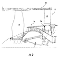
- Figures 1 and 2 depict a gas turbine engine 10 incorporating an OGV heat exchanger apparatus constructed according to an aspect of the present invention. While the illustrated example is a high-bypass turbofan engine, the principles of the present invention are also applicable to other types of engines, such as low-bypass, turbojet, etc.
- the engine 10 has a longitudinal center line or axis A and an outer stationary annular casing 12 disposed concentrically about and coaxially along the axis A.
- the engine 10 has a fan 14, booster 16, compressor 18, combustor 20, high pressure turbine 22, and low pressure turbine 24 arranged in serial flow relationship.
- pressurized air from the compressor 18 is mixed with fuel in the combustor 20 and ignited, thereby generating combustion gases. Some work is extracted from these gases by the high pressure turbine 22 which drives the compressor 18 via an outer shaft 26. The combustion gases then flow into a low pressure turbine 24, which drives the fan 14 and booster 16 via an inner shaft 28.
- the inner and outer shafts 28 and 26 are rotatably mounted in bearings 30 which are themselves mounted in a fan frame 32 and a turbine rear frame 34.
- the fan frame 32 has a central hub 36 connected to an annular fan casing 38 by an annular array of radially extending fan outlet guide vanes ("OGVs") 40 which extend across the fan flowpath.
- OGVs fan outlet guide vanes
- each of the OGVs 40 is both an aero-turning element and a structural support for the fan casing 38.
- separate members are provided for the aerodynamic and structural functions. While the concepts of the present invention will be described using the OGVs 40 as an example, it will be understood that those concepts are applicable to any stationary airfoil-type structure within the engine 10.
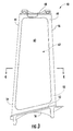
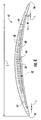
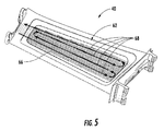
- FIG. 3-5 illustrate one of the fan OGVs 40 in more detail.
- the OGV comprises an airfoil 42 having a leading edge 44, a trailing edge 46, a tip 48, a root 50, a convex suction side 52, and a concave pressure side 54.
- An arcuate inner platform 56 is disposed at the root 50 of the airfoil 42.
- the airfoil 42 is assembled from a body 58 and a cover 60.
- the body 58 and the cover 60 are both made from a material with suitable strength and weight characteristics for the intended application.
- a suitable alloy is a 7000 series aluminum alloy, in particular a 7075 aluminum alloy.
- the body 58 is a unitary component which may be produced by forging, for example. It incorporates a plenum 62 (see Figure 4 ) configured as a pocket formed in its pressure side 54. Alternatively or in addition, the plenum 62 could also comprise a pocket formed in the suction side 52.
- the cover 60 may be secured to the ledge 64 by any means which provides a secure, leak-free joint, such as adhesive bonding, fusion welding, or a solid-state bond such as that produced by friction stir welding.
- the cover 60 may further be secured to structures of the airfoil 42 within the perimeter of the plenum 62 (e.g. walls, ribs, etc., described in more detail below) in order to prevent fluid leakage between various channels and flow paths defined within the airfoil 42.
- This ledge 64 has an average width "W" which is selected to be as narrow as possible to save weight and material, while still leaving enough material for a full penetration weld through the cover 60. In the illustrated example, the width W is less than about 1.27 cm (0.5 in.) and is preferably about 0.89 cm (0.35 in.)
- the cover 60 is a unitary component including inner and outer surfaces which fits down into the plenum 62 so that the outer surface 65 is substantially flush with the pressure side 22 of the airfoil 42.
- the outer surface 65 of the cover 60 forms a portion of the pressure side 22 of the airfoil 42.
- the cover 60 is generally rectangular with radiused corners. It serves only as an aerodynamic element and may have a relatively small thickness, for example approximately 2 mm (0.08 in.).
- the periphery of the cover 60 is fitted to the periphery of the plenum 62 with a small lateral tolerance "L", for example about 0.127 mm (0.005 in.)
- the plenum 62 provides a space within the OGV 40 for a flow of working fluid, for example lubrication oil.
- the plenum 62 is integral to the OGV 40, or in other words, the plenum 62 is defined by the structure of the OGV 40 itself, rather than any intermediate structure, such as filler materials used in the prior art. In operation, this results in working fluid being in intimate contact with the inner surface of the skin of the OGV 40 so as to maximize heat transfer rate.
- the interior of the plenum 62 i.e. its size, shape, surface texture, and arrangement of internal walls or other features, may be configured to maximize heat transfer between the working fluid and the OGV 40, minimize pressure loses, and so forth.
- the term "plenum" refers to the entire volume available for flow of working fluid within the OGV 40, regardless of whether it is configured as a unitary space or several smaller spaces.
- the interior of the plenum 62 is configured as a plurality of parallel channels 66 running in a generally radial (i.e. spanwise) direction and separated by walls or ribs.
- Groups of the channels 66 may be arranged into serpentine "passes" which are shown schematically by the arrows labeled 68.
- the passes may be defined by channels integrally formed within the OGV 40 or by a tube or header structure external to the OGV 40.
- the channels 66 may be formed, for example, by a machining process before the cover 60 is installed as described above.
- the width of each of the channels 66 is approximately 6.4 mm (0.25 in.).
- the number of channels 66 and their cross-sectional design may be selected so that the flow area of each pass 68 is substantially equal to a commonly available tubing size.
- FIG. 6 illustrates an OGV 140 incorporating an alternative plenum 162.
- the plenum 162 includes a central septum 164 which runs in a generally spanwise direction in approximately a mid-chord location within the plenum 162.
- a plurality of inner walls 166 extend forward and aft from the septum 164 at intervals along its length.
- a plurality of outer walls 168 extend inboard from the periphery of the plenum 162 at alternate spanwise locations relative to the inner walls 166.
- the septum 164 and inner and outer walls 166 and 168 define a serpentine flowpath which follows a generally "U"-shaped path through the plenum 162.
- Figure 7 illustrates yet another alternative OGV 240 incorporating an alternative plenum 262.
- An array of first walls 264 lie in a first plane and extend across the plenum at a first acute angle.
- An array of second walls 266 lie underneath the first walls 264 in a second plane and extend across the plenum 262 perpendicular to the first walls 264.
- Working fluid is introduced to the first plane and flows parallel to the first walls 264 until it reaches their ends, where it flows across to the second plane and parallel to the second walls 266, thus generating a cross-flow action.
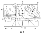
- FIG 8 illustrates a structure for transferring working fluid to and from the OGV 40.
- the tip 48 of the OGV 40 has inlet and outlet ports 72 and 74 formed therein, communicating with the plenum 62.
- An inlet jumper tube assembly 76 is coupled to the inlet port 72, and an outlet jumper tube assembly 78 is coupled to the outlet port 74.
- the ports 72 and 74 are substantially identical in construction, accordingly only the inlet port 72 and its associated inlet jumper tube assembly 76 will be described in detail.
- the inlet port 72 has an opening 79 located at the outer face of the OGV 40.
- the inner end of a generally cylindrical jumper tube 80 is received in the inlet port 72.
- the jumper tube 80 spans the radial gap between the tip 48 of the OGV 40 and the fan casing 38 and passes through an opening in the fan casing 38.
- the outer end of the jumper tube 80 is received in a hollow retainer 82.
- Seals 84 and 86 such as the illustrated "O"-rings, prevent leakage between the jumper tube-to-OGV and jumper tube-to-retainer interfaces, while permitting some relative motion between the OGV 40 and the fan casing 38.
- the retainer 82 is secured to the outer surface of the fan casing 38.
- the retainer 82 is clamped to the fan casing 38 using fasteners of a conventional type such as bolts (not shown) passing through holes 88 in the fan casing 38 and a mounting flange 90 of the retainer 82.
- the outer end of the retainer 82 has a fluid fitting 92 installed therein, which in the illustrated example is an elbow.
- the fluid fitting 92 is connected in turn to a supply tube (not shown).
- hot working fluid from the engine e.g. lubricating oil or accessory cooling oil
- the working fluid flows through the plenum 62 where heat is removed from the fluid by transfer to the airflow surrounding the OGV (in this case fan bypass flow).
- the heated oil then passes out through the outlet jumper tube assembly 78 and back to the remainder of the oil system.
- the oil circulation flow through the OGVs 40 may be parallel or serial as dictated by the particular application. It will be understood that the oil system incorporates pumps, filters, lines, valves, tanks, and other equipment as needed to provide a flow of pressurized oil. Such components are well-known and therefore not illustrated here.
- turbine engine OGVs will incorporate an oil cooling function, in addition to aero-turning and structural functions.
- the oil cooling function is performed at the periphery of the vane to take advantage of the heat exchange along the pressure and suction sides of the airfoil and as such is
- This concept has several advantages. Among them are substantially lower oil pressure drop than prior art ACOCs, as well as lower noise levels, and a substantial weight savings from eliminating ACOCs and the associated engine "FRTT”. A significant improvement in specific fuel consumption (“SFC”) is expected as well.
Landscapes
- Engineering & Computer Science (AREA)
- Mechanical Engineering (AREA)
- General Engineering & Computer Science (AREA)
- Physics & Mathematics (AREA)
- Fluid Mechanics (AREA)
- Chemical & Material Sciences (AREA)
- Combustion & Propulsion (AREA)
- Turbine Rotor Nozzle Sealing (AREA)
- Structures Of Non-Positive Displacement Pumps (AREA)
Applications Claiming Priority (1)
| Application Number | Priority Date | Filing Date | Title |
|---|---|---|---|
| US12/771,508 US8616834B2 (en) | 2010-04-30 | 2010-04-30 | Gas turbine engine airfoil integrated heat exchanger |
Publications (2)
| Publication Number | Publication Date |
|---|---|
| EP2383437A2 true EP2383437A2 (de) | 2011-11-02 |
| EP2383437A3 EP2383437A3 (de) | 2018-01-03 |
Family
ID=44148960
Family Applications (1)
| Application Number | Title | Priority Date | Filing Date |
|---|---|---|---|
| EP11164073.6A Withdrawn EP2383437A3 (de) | 2010-04-30 | 2011-04-28 | In Schaufel integrierter Wärmtauscher in einem Gasturbinentriebwerk |
Country Status (4)
| Country | Link |
|---|---|
| US (1) | US8616834B2 (de) |
| EP (1) | EP2383437A3 (de) |
| JP (1) | JP5866090B2 (de) |
| CA (1) | CA2737338A1 (de) |
Cited By (12)
| Publication number | Priority date | Publication date | Assignee | Title |
|---|---|---|---|---|
| WO2013150248A1 (fr) * | 2012-04-05 | 2013-10-10 | Snecma | Aubage de redressement de sortie |
| FR2989110A1 (fr) * | 2012-04-05 | 2013-10-11 | Snecma | Aube de stator formee par un ensemble de parties d'aube |
| FR2989108A1 (fr) * | 2012-04-05 | 2013-10-11 | Snecma | Partie de stator comportant une aube de stator et une structure de conduction thermique |
| GB2517579A (en) * | 2013-07-18 | 2015-02-25 | Hamilton Sundstrand Corp | Fluid cooling arrangement for a gas turbine engine and method |
| FR3028576A1 (fr) * | 2014-11-19 | 2016-05-20 | Snecma | Secteur d'aubage de stator d'une turbomachine comprenant des canaux de circulation de fluide chaud |
| EP3115558A1 (de) * | 2015-07-01 | 2017-01-11 | Rolls-Royce Deutschland Ltd & Co KG | Leitschaufel eines gasturbinentriebwerks |
| EP3187724A1 (de) * | 2015-12-28 | 2017-07-05 | General Electric Company | Verfahren und system für kombinationswärmetauscher |
| EP2904252B1 (de) | 2012-10-01 | 2017-12-06 | United Technologies Corporation | Statische leitschaufel mit internen hohlen kanälen |
| EP3486429A1 (de) * | 2017-11-16 | 2019-05-22 | General Electric Company | Ogv-elektrogeformte wärmetauscher |
| GB2569695A (en) * | 2016-09-02 | 2019-06-26 | Rolls Royce Plc | Gas turbine engine |
| WO2019122657A1 (fr) * | 2017-12-21 | 2019-06-27 | Safran Aircraft Engines | Aube fixe de redresseur d'une soufflante de turbomachine |
| EP3527784A1 (de) * | 2018-02-15 | 2019-08-21 | United Technologies Corporation | Kühlbare leitschaufel für einen gasturbinenmotor |
Families Citing this family (74)
| Publication number | Priority date | Publication date | Assignee | Title |
|---|---|---|---|---|
| FR2978196B1 (fr) * | 2011-07-20 | 2016-12-09 | Snecma | Aubes de turbomachine comprenant une plaque rapportee sur une partie principale |
| GB201200253D0 (en) * | 2012-01-09 | 2012-02-22 | Isis Innovation | Monitoring engine components |
| EP2700798A1 (de) * | 2012-08-21 | 2014-02-26 | Siemens Aktiengesellschaft | Strömungsmaschine umfassend einen Rotor und ein Gehäuse |
| US10982551B1 (en) | 2012-09-14 | 2021-04-20 | Raytheon Technologies Corporation | Turbomachine blade |
| US9441496B2 (en) * | 2012-09-26 | 2016-09-13 | United Technologies Corporation | Structural guide vane internal topology |
| US20140165570A1 (en) * | 2012-12-18 | 2014-06-19 | United Technologies Corporation | Oscillating heat pipe for thermal management of gas turbine engines |
| GB201302262D0 (en) * | 2013-02-08 | 2013-03-27 | Rolls Royce Plc | Manufacture of hollow aerofoil |
| ITTV20130031A1 (it) | 2013-02-28 | 2014-08-29 | Pietro Rosa T B M S R L | Paletta per turbomacchine e relativo metodo di costruzione |
| ITTV20130029A1 (it) * | 2013-02-28 | 2014-08-29 | Pietro Rosa T B M S R L | Paletta per turbomacchine e relativo metodo di costruzione |
| WO2014137415A1 (en) * | 2013-03-08 | 2014-09-12 | United Technologies Corporation | Covers for cavities in aircraft fan blades |
| FR3006367B1 (fr) * | 2013-05-28 | 2015-07-03 | Snecma | Aube creuse, et son procede de fabrication |
| US20150260127A1 (en) * | 2014-03-13 | 2015-09-17 | Arthur J. Wennerstrom | Aircraft Turbofan Engine with Multiple High-Pressure Core Modules Not Concentric with the Engine Centerline |
| US10660236B2 (en) | 2014-04-08 | 2020-05-19 | General Electric Company | Systems and methods for using additive manufacturing for thermal management |
| US10356945B2 (en) | 2015-01-08 | 2019-07-16 | General Electric Company | System and method for thermal management using vapor chamber |
| US9726023B2 (en) * | 2015-01-26 | 2017-08-08 | United Technologies Corporation | Airfoil support and cooling scheme |
| US9909448B2 (en) | 2015-04-15 | 2018-03-06 | General Electric Company | Gas turbine engine component with integrated heat pipe |
| GB201506901D0 (en) * | 2015-04-23 | 2015-06-10 | Rolls Royce Plc | Manufacture of a hollow aerofoil |
| US10196932B2 (en) | 2015-12-08 | 2019-02-05 | General Electric Company | OGV heat exchangers networked in parallel and serial flow |
| FR3046811B1 (fr) * | 2016-01-15 | 2018-02-16 | Snecma | Aube directrice de sortie pour turbomachine d'aeronef, presentant une fonction amelioree de refroidissement de lubrifiant |
| US10577973B2 (en) | 2016-02-18 | 2020-03-03 | General Electric Company | Service tube for a turbine engine |
| FR3049644B1 (fr) | 2016-04-01 | 2018-04-13 | Safran Aircraft Engines | Aube directrice de sortie pour turbomachine d'aeronef, presentant une fonction amelioree de refroidissement de lubrifiant a l'aide d'une matrice de conduction thermique logee dans un passage interieur de l'aube |
| US10260523B2 (en) * | 2016-04-06 | 2019-04-16 | Rolls-Royce North American Technologies Inc. | Fluid cooling system integrated with outlet guide vane |
| US10209009B2 (en) | 2016-06-21 | 2019-02-19 | General Electric Company | Heat exchanger including passageways |
| FR3054263B1 (fr) * | 2016-07-20 | 2018-08-10 | Safran Aircraft Engines | Carter intermediaire de turbomachine d'aeronef realise d'une seule piece de fonderie avec une canalisation de lubrifiant |
| US20180038386A1 (en) * | 2016-08-08 | 2018-02-08 | United Technologies Corporation | Fan blade with composite cover |
| US10309242B2 (en) * | 2016-08-10 | 2019-06-04 | General Electric Company | Ceramic matrix composite component cooling |
| US10563666B2 (en) * | 2016-11-02 | 2020-02-18 | United Technologies Corporation | Fan blade with cover and method for cover retention |
| FR3059353B1 (fr) | 2016-11-29 | 2019-05-17 | Safran Aircraft Engines | Aube directrice de sortie pour turbomachine d'aeronef, comprenant une zone coudee de passage de lubrifiant presentant une conception amelioree |
| US11261737B1 (en) | 2017-01-17 | 2022-03-01 | Raytheon Technologies Corporation | Turbomachine blade |
| US11199096B1 (en) | 2017-01-17 | 2021-12-14 | Raytheon Technologies Corporation | Turbomachine blade |
| US10801364B1 (en) * | 2017-01-17 | 2020-10-13 | Raytheon Technologies Corporation | Gas turbine engine airfoil frequency design |
| US10830056B2 (en) | 2017-02-03 | 2020-11-10 | General Electric Company | Fluid cooling systems for a gas turbine engine |
| US10514005B2 (en) * | 2017-02-24 | 2019-12-24 | Unison Industries, Llc | Turbine engine thermal seal |
| FR3063767B1 (fr) * | 2017-03-13 | 2019-04-26 | Safran Aircraft Engines | Aube directrice de sortie pour turbomachine d'aeronef, a fonction amelioree de refroidissement de lubrifiant |
| FR3064296B1 (fr) * | 2017-03-23 | 2019-06-07 | Safran Aircraft Engines | Carter intermediaire de turbomachine d'aeronef comprenant une piece intermediaire entre un pied d'aube et le moyeu |
| FR3064295B1 (fr) * | 2017-03-23 | 2019-06-07 | Safran Aircraft Engines | Carter intermediaire de turbomachine d'aeronef comprenant un embout de passage de lubrifiant solidaire d'une plateforme |
| FR3064682B1 (fr) * | 2017-03-31 | 2019-06-14 | Safran Aircraft Engines | Carter intermediaire de turbomachine d'aeronef comprenant un embout de passage de lubrifiant connecte a une aube de carter par une piece de raccord |
| FR3066532B1 (fr) | 2017-05-22 | 2019-07-12 | Safran Aircraft Engines | Aube directrice de sortie pour turbomachine d'aeronef, comprenant un passage de refroidissement de lubrifiant equipe de plots perturbateurs de flux a fabrication simplifiee |
| US10934936B2 (en) | 2017-07-10 | 2021-03-02 | Rolls-Royce North American Technologies, Inc. | Cooling system in a hybrid electric propulsion gas turbine engine for cooling electrical components therein |
| US10842044B2 (en) * | 2017-07-10 | 2020-11-17 | Rolls-Royce North American Technologies, Inc. | Cooling system in hybrid electric propulsion gas turbine engine |
| FR3071008B1 (fr) | 2017-09-11 | 2019-09-13 | Safran Aircraft Engines | Aube directrice de sortie pour turbomachine, comprenant un passage de refroidissement de lubrifiant equipe d'une matrice de conduction thermique comprimee entre les parois d'intrados et d'extrados |
| FR3075256B1 (fr) * | 2017-12-19 | 2020-01-10 | Safran Aircraft Engines | Aube directrice de sortie pour turbomachine d'aeronef, comprenant un passage de refroidissement de lubrifiant equipe de plots perturbateurs de flux |
| US10443620B2 (en) | 2018-01-02 | 2019-10-15 | General Electric Company | Heat dissipation system for electric aircraft engine |
| FR3077850B1 (fr) * | 2018-02-13 | 2020-03-13 | Safran Aircraft Engines | Aube directrice de sortie pour turbomachine, realisee a partir de plusieurs pieces assemblees entre elles par des moyens de fixation deportes de la veine |
| FR3081912B1 (fr) | 2018-05-29 | 2020-09-04 | Safran Aircraft Engines | Aube de turbomachine comprenant un passage interne d'ecoulement de fluide equipe d'une pluralite d'elements perturbateurs a agencement optimise |
| US10784750B2 (en) | 2018-06-12 | 2020-09-22 | General Electric Company | Electric motor having an integrated cooling system and methods of cooling an electric motor |
| US10968830B2 (en) | 2018-06-22 | 2021-04-06 | Rolls-Royce North American Technologies, Inc. | Systems and methods for cooling electronics and electrical machinery in a hybrid electric aircraft |
| US11146133B2 (en) | 2018-08-30 | 2021-10-12 | General Electric Company | Electric machine with rotor coolant and lubrication distribution system, and systems and methods of cooling and lubricating an electric machine |
| US11165309B2 (en) | 2019-05-10 | 2021-11-02 | Hamilton Sundstrand Corporation | Motor cooling system and method |
| FR3097260B1 (fr) * | 2019-06-12 | 2021-06-11 | Safran Aircraft Engines | Carter de soufflante de turboréacteur |
| US11286881B2 (en) | 2019-10-16 | 2022-03-29 | Rolls-Royce North American Technologies Inc. | Gas turbine engine with reversible heat exchanger |
| US11260976B2 (en) | 2019-11-15 | 2022-03-01 | General Electric Company | System for reducing thermal stresses in a leading edge of a high speed vehicle |
| US11352120B2 (en) | 2019-11-15 | 2022-06-07 | General Electric Company | System and method for cooling a leading edge of a high speed vehicle |
| US11427330B2 (en) | 2019-11-15 | 2022-08-30 | General Electric Company | System and method for cooling a leading edge of a high speed vehicle |
| US11260953B2 (en) | 2019-11-15 | 2022-03-01 | General Electric Company | System and method for cooling a leading edge of a high speed vehicle |
| US11267551B2 (en) | 2019-11-15 | 2022-03-08 | General Electric Company | System and method for cooling a leading edge of a high speed vehicle |
| GB2589125B (en) * | 2019-11-21 | 2022-10-19 | Gkn Aerospace Sweden Ab | Heat exchanger integration |
| DE102019135339A1 (de) | 2019-12-19 | 2021-06-24 | Rolls-Royce Deutschland Ltd & Co Kg | Gasturbinentriebwerk eines Luftfahrzeuges |
| FR3109962B1 (fr) | 2020-05-06 | 2022-04-29 | Safran Aircraft Engines | Aube directrice de sortie pour turbomachine d’aeronef, comprenant un passage de refroidissement de lubrifiant equipe de parois ondulees |
| FR3110630B1 (fr) | 2020-05-20 | 2022-04-29 | Safran Aircraft Engines | Aube directrice de sortie pour turbomachine, realisee a partir de plusieurs pieces assemblees entre elles |
| US12040690B2 (en) | 2020-08-31 | 2024-07-16 | General Electric Company | Cooling a stator housing of an electric machine |
| US11745847B2 (en) | 2020-12-08 | 2023-09-05 | General Electric Company | System and method for cooling a leading edge of a high speed vehicle |
| US11407488B2 (en) | 2020-12-14 | 2022-08-09 | General Electric Company | System and method for cooling a leading edge of a high speed vehicle |
| EP4707715A2 (de) | 2021-01-21 | 2026-03-11 | Parker-Hannifin Corporation | Wärmetauscher mit progressiv geteiltem strömungskreis, struktureller lasttragender konstruktion |
| US11577817B2 (en) | 2021-02-11 | 2023-02-14 | General Electric Company | System and method for cooling a leading edge of a high speed vehicle |
| FR3130876B1 (fr) * | 2021-12-20 | 2024-09-13 | Safran Aircraft Engines | Aube de redresseur comportant un caloduc |
| EP4310430A1 (de) * | 2022-07-19 | 2024-01-24 | Airbus Operations, S.L.U. | Wärmetauscher |
| GB2621336A (en) * | 2022-08-08 | 2024-02-14 | City Univ Of London | Heat transfer system |
| US12312969B2 (en) | 2023-01-17 | 2025-05-27 | General Electric Company | Airfoils for turbofan engines |
| US12234748B2 (en) | 2023-06-14 | 2025-02-25 | General Electric Company | Gas turbine engine having outlet guide vanes |
| US12331684B2 (en) | 2023-11-07 | 2025-06-17 | Rtx Corporation | Strut microtube counterflow evaporator |
| FR3155559B1 (fr) | 2023-11-16 | 2025-10-03 | Safran Aircraft Engines | Dispositif hydraulique pour circuit de lubrifiant de turbomachine d’aeronef |
| US12516607B1 (en) | 2024-07-08 | 2026-01-06 | Rtx Corporation | Fan load tension structural guide vane with bypass cooling cavities |
| US12607132B1 (en) | 2025-02-17 | 2026-04-21 | General Electric Company | Heat exchanger assembly configuration for a gas turbine engine |
Family Cites Families (16)
| Publication number | Priority date | Publication date | Assignee | Title |
|---|---|---|---|---|
| US2620157A (en) * | 1947-05-06 | 1952-12-02 | Rolls Royce | Gas-turbine engine |
| US2977090A (en) * | 1956-06-12 | 1961-03-28 | Daniel J Mccarty | Heat responsive means for blade cooling |
| US3220697A (en) * | 1963-08-30 | 1965-11-30 | Gen Electric | Hollow turbine or compressor vane |
| US3486833A (en) * | 1967-05-05 | 1969-12-30 | Gen Motors Corp | High temperature composite gas turbine engine components |
| BE794195A (fr) * | 1972-01-18 | 1973-07-18 | Bbc Sulzer Turbomaschinen | Aube directrice refroidie pour des turbines a gaz |
| US4245951A (en) * | 1978-04-26 | 1981-01-20 | General Motors Corporation | Power turbine support |
| US5468125A (en) * | 1994-12-20 | 1995-11-21 | Alliedsignal Inc. | Turbine blade with improved heat transfer surface |
| JP3564290B2 (ja) * | 1997-12-24 | 2004-09-08 | 三菱重工業株式会社 | 蒸気冷却型ガスタービン |
| US5971708A (en) * | 1997-12-31 | 1999-10-26 | General Electric Company | Branch cooled turbine airfoil |
| AU2001213231A1 (en) * | 2000-11-10 | 2002-05-21 | Marek Kovac | Bypass gas turbine engine and cooling method for working fluid |
| WO2003080998A1 (de) * | 2002-03-25 | 2003-10-02 | Alstom Technology Ltd | Gekühlte turbinenschaufel |
| FR2852999B1 (fr) * | 2003-03-28 | 2007-03-23 | Snecma Moteurs | Aube allegee de turbomachine et son procede de fabrication |
| US7189064B2 (en) * | 2004-05-14 | 2007-03-13 | General Electric Company | Friction stir welded hollow airfoils and method therefor |
| US7377098B2 (en) | 2004-08-26 | 2008-05-27 | United Technologies Corporation | Gas turbine engine frame with an integral fluid reservoir and air/fluid heat exchanger |
| JP2006336570A (ja) * | 2005-06-03 | 2006-12-14 | Hitachi Ltd | ガスタービン |
| US8333552B2 (en) * | 2008-06-20 | 2012-12-18 | General Electric Company | Combined acoustic absorber and heat exchanging outlet guide vanes |
-
2010
- 2010-04-30 US US12/771,508 patent/US8616834B2/en active Active
-
2011
- 2011-04-14 CA CA2737338A patent/CA2737338A1/en not_active Abandoned
- 2011-04-21 JP JP2011094558A patent/JP5866090B2/ja not_active Expired - Fee Related
- 2011-04-28 EP EP11164073.6A patent/EP2383437A3/de not_active Withdrawn
Non-Patent Citations (1)
| Title |
|---|
| None |
Cited By (24)
| Publication number | Priority date | Publication date | Assignee | Title |
|---|---|---|---|---|
| FR2989110A1 (fr) * | 2012-04-05 | 2013-10-11 | Snecma | Aube de stator formee par un ensemble de parties d'aube |
| FR2989108A1 (fr) * | 2012-04-05 | 2013-10-11 | Snecma | Partie de stator comportant une aube de stator et une structure de conduction thermique |
| GB2515961A (en) * | 2012-04-05 | 2015-01-07 | Snecma | Exit guide vanes |
| US10145253B2 (en) | 2012-04-05 | 2018-12-04 | Safran Aircraft Engines | Stator vane formed by a set of vane parts |
| WO2013150248A1 (fr) * | 2012-04-05 | 2013-10-10 | Snecma | Aubage de redressement de sortie |
| GB2515961B (en) * | 2012-04-05 | 2018-06-27 | Snecma | Stator vane formed by a set of vane parts |
| EP2904252B1 (de) | 2012-10-01 | 2017-12-06 | United Technologies Corporation | Statische leitschaufel mit internen hohlen kanälen |
| EP2904252B2 (de) † | 2012-10-01 | 2020-11-25 | United Technologies Corporation | Statische leitschaufel mit internen hohlen kanälen |
| GB2517579B (en) * | 2013-07-18 | 2016-09-28 | Hamilton Sundstrand Corp | Fluid cooling arrangement for a gas turbine engine and method |
| GB2517579A (en) * | 2013-07-18 | 2015-02-25 | Hamilton Sundstrand Corp | Fluid cooling arrangement for a gas turbine engine and method |
| US9726029B2 (en) | 2013-07-18 | 2017-08-08 | Hamilton Sundstrand Corporation | Fluid cooling arrangement for a gas turbine engine and method |
| FR3028576A1 (fr) * | 2014-11-19 | 2016-05-20 | Snecma | Secteur d'aubage de stator d'une turbomachine comprenant des canaux de circulation de fluide chaud |
| US10634006B2 (en) | 2015-07-01 | 2020-04-28 | Rolls-Royce Deutschland Ltd & Co Kg | Guide vane of a gas turbine engine, in particular of an aircraft engine |
| EP3115558A1 (de) * | 2015-07-01 | 2017-01-11 | Rolls-Royce Deutschland Ltd & Co KG | Leitschaufel eines gasturbinentriebwerks |
| CN107035527A (zh) * | 2015-12-28 | 2017-08-11 | 通用电气公司 | 用于组合式换热器的方法及系统 |
| EP3187724A1 (de) * | 2015-12-28 | 2017-07-05 | General Electric Company | Verfahren und system für kombinationswärmetauscher |
| GB2569695A (en) * | 2016-09-02 | 2019-06-26 | Rolls Royce Plc | Gas turbine engine |
| EP3486429A1 (de) * | 2017-11-16 | 2019-05-22 | General Electric Company | Ogv-elektrogeformte wärmetauscher |
| US11078795B2 (en) | 2017-11-16 | 2021-08-03 | General Electric Company | OGV electroformed heat exchangers |
| US11549376B2 (en) | 2017-11-16 | 2023-01-10 | General Electric Company | OGV electroformed heat exchangers |
| FR3075870A1 (fr) * | 2017-12-21 | 2019-06-28 | Safran Aircraft Engines | Aube fixe de turbomachine, dans un redresseur de soufflante |
| WO2019122657A1 (fr) * | 2017-12-21 | 2019-06-27 | Safran Aircraft Engines | Aube fixe de redresseur d'une soufflante de turbomachine |
| US11149566B2 (en) | 2017-12-21 | 2021-10-19 | Safran Aircraft Engines | Guide vane for a turbomachine fan |
| EP3527784A1 (de) * | 2018-02-15 | 2019-08-21 | United Technologies Corporation | Kühlbare leitschaufel für einen gasturbinenmotor |
Also Published As
| Publication number | Publication date |
|---|---|
| US20110268562A1 (en) | 2011-11-03 |
| CA2737338A1 (en) | 2011-10-30 |
| EP2383437A3 (de) | 2018-01-03 |
| JP2011236894A (ja) | 2011-11-24 |
| US8616834B2 (en) | 2013-12-31 |
| JP5866090B2 (ja) | 2016-02-17 |
Similar Documents
| Publication | Publication Date | Title |
|---|---|---|
| US8616834B2 (en) | Gas turbine engine airfoil integrated heat exchanger | |
| US12510027B2 (en) | Gas turbine engines with heat recovery systems | |
| US10443436B2 (en) | Modular annular heat exchanger | |
| US12281850B2 (en) | Multi-fluid heat exchanger | |
| JP5898901B2 (ja) | タービンロータブレードのプラットフォーム領域を冷却する装置およびその方法 | |
| EP3179048A1 (de) | Parallel und seriell vernetzte leitschaufelwärmetauscher | |
| US20180363555A1 (en) | Combustion Section Heat Transfer System for a Propulsion System | |
| EP3382240A1 (de) | Dichtungselement mit internem schmiermittelplenum für eine rotationsausrüstung | |
| CN102444431A (zh) | 用于冷却涡轮转子叶片平台区的装置与方法 | |
| EP4372213A1 (de) | Schmiermittelbehälter mit integriertem wärmetauscher | |
| US20170335692A1 (en) | Refractory metal core and components formed thereby | |
| EP4428478B1 (de) | Wärmetauscher mit gekreuzten wärmetauscherrohren | |
| EP4361423A2 (de) | Gasturbinenmotorkomponente mit integriertem wärmetauscher | |
| US11021961B2 (en) | Rotor assembly thermal attenuation structure and system | |
| CN120575987B (zh) | 具有柔性接头的旋转机器的密封组件 | |
| US12044170B2 (en) | Closed-loop cooling system for a gas turbine engine | |
| CN116658305A (zh) | 表面冷却器和形成的方法 | |
| EP3569819B1 (de) | Mehrfachquellenablenkplatten für gasturbinenmotorkomponenten | |
| US10323569B2 (en) | Core assemblies and gas turbine engine components formed therefrom | |
| CN118167480A (zh) | 集成式发动机入口框架空气冷却的油冷却设备 |
Legal Events
| Date | Code | Title | Description |
|---|---|---|---|
| AK | Designated contracting states |
Kind code of ref document: A2 Designated state(s): AL AT BE BG CH CY CZ DE DK EE ES FI FR GB GR HR HU IE IS IT LI LT LU LV MC MK MT NL NO PL PT RO RS SE SI SK SM TR |
|
| AX | Request for extension of the european patent |
Extension state: BA ME |
|
| PUAI | Public reference made under article 153(3) epc to a published international application that has entered the european phase |
Free format text: ORIGINAL CODE: 0009012 |
|
| PUAL | Search report despatched |
Free format text: ORIGINAL CODE: 0009013 |
|
| AK | Designated contracting states |
Kind code of ref document: A3 Designated state(s): AL AT BE BG CH CY CZ DE DK EE ES FI FR GB GR HR HU IE IS IT LI LT LU LV MC MK MT NL NO PL PT RO RS SE SI SK SM TR |
|
| AX | Request for extension of the european patent |
Extension state: BA ME |
|
| RIC1 | Information provided on ipc code assigned before grant |
Ipc: F01D 9/04 20060101ALI20171129BHEP Ipc: F02K 3/06 20060101ALI20171129BHEP Ipc: F01D 5/18 20060101AFI20171129BHEP Ipc: F01D 9/06 20060101ALI20171129BHEP Ipc: F01D 25/12 20060101ALI20171129BHEP Ipc: F01D 25/18 20060101ALI20171129BHEP |
|
| STAA | Information on the status of an ep patent application or granted ep patent |
Free format text: STATUS: THE APPLICATION IS DEEMED TO BE WITHDRAWN |
|
| 18D | Application deemed to be withdrawn |
Effective date: 20180704 |