EP2383442A2 - Moteur à turbine à gaz - Google Patents
Moteur à turbine à gaz Download PDFInfo
- Publication number
- EP2383442A2 EP2383442A2 EP11162565A EP11162565A EP2383442A2 EP 2383442 A2 EP2383442 A2 EP 2383442A2 EP 11162565 A EP11162565 A EP 11162565A EP 11162565 A EP11162565 A EP 11162565A EP 2383442 A2 EP2383442 A2 EP 2383442A2
- Authority
- EP
- European Patent Office
- Prior art keywords
- bifurcator
- bypass duct
- gas turbine
- turbine engine
- air
- Prior art date
- Legal status (The legal status is an assumption and is not a legal conclusion. Google has not performed a legal analysis and makes no representation as to the accuracy of the status listed.)
- Withdrawn
Links
- 238000007599 discharging Methods 0.000 claims description 12
- 230000007704 transition Effects 0.000 claims description 7
- 239000003570 air Substances 0.000 description 81
- 238000009434 installation Methods 0.000 description 8
- 230000003993 interaction Effects 0.000 description 8
- 230000009467 reduction Effects 0.000 description 6
- 230000000694 effects Effects 0.000 description 5
- 238000011144 upstream manufacturing Methods 0.000 description 4
- 230000008901 benefit Effects 0.000 description 3
- 230000000875 corresponding effect Effects 0.000 description 3
- 230000007246 mechanism Effects 0.000 description 3
- 238000007664 blowing Methods 0.000 description 2
- 230000008859 change Effects 0.000 description 2
- 230000003247 decreasing effect Effects 0.000 description 2
- 238000000926 separation method Methods 0.000 description 2
- 210000001364 upper extremity Anatomy 0.000 description 2
- 239000012080 ambient air Substances 0.000 description 1
- 230000009286 beneficial effect Effects 0.000 description 1
- 230000015572 biosynthetic process Effects 0.000 description 1
- 230000001276 controlling effect Effects 0.000 description 1
- 230000002596 correlated effect Effects 0.000 description 1
- 239000012530 fluid Substances 0.000 description 1
- 210000003141 lower extremity Anatomy 0.000 description 1
- 238000000034 method Methods 0.000 description 1
- 239000000203 mixture Substances 0.000 description 1
- 230000004048 modification Effects 0.000 description 1
- 238000012986 modification Methods 0.000 description 1
- 230000003313 weakening effect Effects 0.000 description 1
Images




Classifications
-
- F—MECHANICAL ENGINEERING; LIGHTING; HEATING; WEAPONS; BLASTING
- F01—MACHINES OR ENGINES IN GENERAL; ENGINE PLANTS IN GENERAL; STEAM ENGINES
- F01D—NON-POSITIVE DISPLACEMENT MACHINES OR ENGINES, e.g. STEAM TURBINES
- F01D25/00—Component parts, details, or accessories, not provided for in, or of interest apart from, other groups
- F01D25/16—Arrangement of bearings; Supporting or mounting bearings in casings
- F01D25/162—Bearing supports
-
- B—PERFORMING OPERATIONS; TRANSPORTING
- B64—AIRCRAFT; AVIATION; COSMONAUTICS
- B64D—EQUIPMENT FOR FITTING IN OR TO AIRCRAFT; FLIGHT SUITS; PARACHUTES; ARRANGEMENT OR MOUNTING OF POWER PLANTS OR PROPULSION TRANSMISSIONS IN AIRCRAFT
- B64D33/00—Arrangement in aircraft of power plant parts or auxiliaries not otherwise provided for
- B64D33/04—Arrangement in aircraft of power plant parts or auxiliaries not otherwise provided for of exhaust outlets or jet pipes
- B64D33/06—Silencing exhaust or propulsion jets
-
- F—MECHANICAL ENGINEERING; LIGHTING; HEATING; WEAPONS; BLASTING
- F01—MACHINES OR ENGINES IN GENERAL; ENGINE PLANTS IN GENERAL; STEAM ENGINES
- F01D—NON-POSITIVE DISPLACEMENT MACHINES OR ENGINES, e.g. STEAM TURBINES
- F01D25/00—Component parts, details, or accessories, not provided for in, or of interest apart from, other groups
- F01D25/28—Supporting or mounting arrangements, e.g. for turbine casing
-
- F—MECHANICAL ENGINEERING; LIGHTING; HEATING; WEAPONS; BLASTING
- F02—COMBUSTION ENGINES; HOT-GAS OR COMBUSTION-PRODUCT ENGINE PLANTS
- F02C—GAS-TURBINE PLANTS; AIR INTAKES FOR JET-PROPULSION PLANTS; CONTROLLING FUEL SUPPLY IN AIR-BREATHING JET-PROPULSION PLANTS
- F02C7/00—Features, components parts, details or accessories, not provided for in, or of interest apart form groups F02C1/00 - F02C6/00; Air intakes for jet-propulsion plants
- F02C7/20—Mounting or supporting of plant; Accommodating heat expansion or creep
-
- F—MECHANICAL ENGINEERING; LIGHTING; HEATING; WEAPONS; BLASTING
- F02—COMBUSTION ENGINES; HOT-GAS OR COMBUSTION-PRODUCT ENGINE PLANTS
- F02K—JET-PROPULSION PLANTS
- F02K3/00—Plants including a gas turbine driving a compressor or a ducted fan
- F02K3/02—Plants including a gas turbine driving a compressor or a ducted fan in which part of the working fluid by-passes the turbine and combustion chamber
- F02K3/04—Plants including a gas turbine driving a compressor or a ducted fan in which part of the working fluid by-passes the turbine and combustion chamber the plant including ducted fans, i.e. fans with high volume, low pressure outputs, for augmenting the jet thrust, e.g. of double-flow type
- F02K3/06—Plants including a gas turbine driving a compressor or a ducted fan in which part of the working fluid by-passes the turbine and combustion chamber the plant including ducted fans, i.e. fans with high volume, low pressure outputs, for augmenting the jet thrust, e.g. of double-flow type with front fan
-
- F—MECHANICAL ENGINEERING; LIGHTING; HEATING; WEAPONS; BLASTING
- F05—INDEXING SCHEMES RELATING TO ENGINES OR PUMPS IN VARIOUS SUBCLASSES OF CLASSES F01-F04
- F05D—INDEXING SCHEME FOR ASPECTS RELATING TO NON-POSITIVE-DISPLACEMENT MACHINES OR ENGINES, GAS-TURBINES OR JET-PROPULSION PLANTS
- F05D2240/00—Components
- F05D2240/10—Stators
- F05D2240/14—Casings or housings protecting or supporting assemblies within
Definitions
- the present invention relates to a gas turbine engine, and in particular to a gas turbine engine in which there is bifurcation of air flow through a bypass duct of the engine.
- Aircraft noise is a major problem in the aircraft industry. Aircraft manufacturers are under continual pressure to reduce the amount of noise produced by aircraft, particularly during takeoff and landing. Significant noise can be caused by aircraft gas turbine engines. In particular, the downstream mixing of flow exiting from bypass and core sections of such an engine can generate jet noise.
- WO2008/045064A1 proposes a variable noise control system in which a controller is programmed to manipulate the core nozzle exit area, for example through the use of hinged flaps. This allows control of the gas flow speed and orientation. Reducing the velocity of the exhaust gas from the core flow reduces the jet noise.
- a disadvantage of such a method is that there is an increase in drag due to the formation of wake and recirculation regions behind the flaps.
- US2008/0166227A1 similarly proposes a mechanism for controlling and varying a nozzle exit area.
- the nozzle exit area is varied using a member on the surface of the nozzle which can be deformed, for example using a mechanical actuator.
- EP1936172A2 proposes an aircraft nozzle attachable to an aircraft turbofan engine wherein multiple flow passages are provided between the bypass and core flows and between the bypass flow and the ambient air, allowing mixing of the different flows. Increased mixing of the flows in the region of the engine nozzle reduces the jet noise caused by the subsequent mixing downstream of the engine.
- US6502383B1 proposes the inclusion of circumferentially spaced apart stub airfoils in the engine ducts.
- the airfoils are disposed adjacent to the outlet of the bypass duct and the outlet of the core duct.
- the airfoils shed vortices which increase the mixing of the exhaust flow.
- US6820410B2 and WO2008/045091A1 propose the use of flow path directors, and describe how the bypass or core flows can be controlled using moveable flaps and moveable inserts respectively. These can be used to vary the area of the engine nozzle during different stages of a flight, for example take off or cruising at altitude.
- US7472543B2 proposes the use of stream path directors in the bypass or core ducts to bifurcate the flow and to direct part of the flow away from the central axis of the engine.
- the stream path directors are shown in the figures (for example Figure 5 and Figure 6 ) as spanning between the fan nacelle and the core shroud (i.e. core fairing), or between the core shroud and the core nozzle, in a radial direction of the engine.
- An object of the present invention is to exert control on the bypass flow of a gas turbine engine, in order to reduce the jet noise from the downstream mixing of the core and bypass flows and/or the installation noise caused by the interaction between the jet shear layer and the wing flaps of the aircraft.
- Noise reduction can be achieved in a number of ways including deflection of the jet shear layer away from the wing flaps of the aircraft, reduction of the strength of the jet shear layer, enhanced mixing of the core and bypass flows and redistribution of the air flow in the vicinity of an attachment pylon for the engine.
- the present invention provides a gas turbine engine comprising:
- a first aspect of the present invention provides a gas turbine engine comprising:
- the varying width of the projected shape produces a varying cross-sectional flow area in the bypass duct.
- This varying flow area can in turn cause pressure variations in the air flow around the bifurcator member and lead to the redistribution of the flow field in the vicinity of the bifurcator member.
- the flow field in the bypass duct can be redistributed around the bifurcator member in different manners through the use of a suitable variation in the width of the projected shape.
- the bifurcator member can alter the radial distribution of the air flow around the engine axis while maintaining the direction of the central axis of the air flow.
- the gas turbine engine of the first aspect may have any one or, to the extent that they are compatible, any combination of the following optional features.
- a bifurcator member of this aspect can be a bypass duct portion of an attachment pylon which attaches the engine to the aircraft, e.g. the wing of an aircraft.
- the bypass duct portion typically spans the bypass duct from the core fairing to the fan nacelle.
- the attachment pylon typically also includes a fairing portion which extends from the outside of the fan nacelle to the aircraft.
- one or more of the bifurcator members can be vanes which, typically, are circumferentially spaced from an attachment pylon.
- the vanes can also, for example, span between the core fairing and the fan nacelle.
- the maximum width of the projected shape of the, or each, bifurcator member can be less than 10% of the span of the member. This limits the drag caused by the presence of the member in the bypass duct.
- the maximum width of the projected shape of the bypass duct portion may be about 25% of the radial distance between the core fairing and the fan nacelle due to mechanical requirements and the need for the attachment pylon to carry fluid systems.
- a suitable width variation of the projected shape may be one in which the width increases with distance from one end of the projected shape to the other end of the projected shape. This width increase may be uniform with distance along the span. Such a width variation can lead to the air flow around the bifurcator member being deflected from the thinner end of the projected shape towards the thicker end of the projected shape.
- a second suitable width variation of the projected shape may be one in which the width increases from both ends of the projected shape towards a position of maximum width between the ends. Such a width variation can lead to the air flow around the bifurcator member being deflected from the thinner ends of the projected shape towards the position of maximum width.
- the width of the projected shape may decrease from both ends of the projected shape towards a position of minimum width between the ends.
- the air flow around the bifurcator member can be deflected from the position of minimum width of the projected shape towards the thicker ends.
- Another suitable width variation of the projected shape may be one where the projected shape has:
- the chord of the bifurcator member i.e. the distance between the leading and the trailing edge of the bifurcator member on a longitudinal cross-section containing the axial direction
- the corresponding width i.e. the width of the projected shape at the longitudinal cross-section containing the chord
- The, or each, bifurcator member may span the annular bypass duct in a radial direction of the engine.
- the subsequent radial variation in the cross-sectional flow area of the bypass duct due to the variation in width of the projected shape, can cause the flow field to be modified radially, altering the radial distribution of the flow around the central axis of the engine.
- radial bifurcator members may be used to narrow or widen the angle of divergence of the outflow of the bypass duct, without altering the direction of the central axis of the flow.
- the, or each, bifurcator member spans the annular bypass duct in a non-radial direction of the engine. This enables circumferential deflection of the flow field as well as radial deflection.
- the positions of the bifurcator members may be driven by structural, mechanical and/or aerodynamic requirements.
- a gas turbine engine comprising:
- the bifurcator member is a vane, which may be circumferentially spaced from an attachment pylon.
- the, or each, bifurcator member has one or more discharge openings on the external surface thereof for discharging air into the bypass duct.
- a gas turbine engine comprising:
- Air blown from discharge openings at or adjacent to the trailing edge of the bifurcator member may be used to generate lift and to further deflect the flow field.
- the bypass flow may be pushed downwards, decreasing the strength of the interaction between the shear layer and the wing of the aircraft and altering the mixing between the core and bypass outflows. This can reduce both the jet noise and the installation noise of the engine.
- a bifurcator member can be a bypass duct portion of an attachment pylon.
- one or more of the bifurcator members can be vanes which span the bypass duct and which may be circumferentially spaced from an attachment pylon.
- the gas turbine engine of the third aspect, or the gas turbine engine of the first or second aspect in which the, or each, bifurcator member has one or more discharge openings may have any one or, to the extent that they are compatible, any combination of the following optional features.
- the discharge openings can be at or adjacent to the trailing edge of the, or each, bifurcator member.
- the air discharged from the discharge openings may be taken from the engine compressor or from airflow over an external fairing, such as a fairing portion of an attachment pylon which connects the engine to the aircraft.
- the, or each, bifurcator member further has:
- openings and passages allow a portion of the air flow through the bypass duct to pass through the bifurcator member, rather than around it.
- openings and passages can reduce the drag caused by the presence of the bifurcator member in the bypass duct. This facilitates the inclusion of larger bifurcator members or a larger number of bifurcator members. It also allows larger variations in cross-sectional shape to be provided, which can lead to more significant pressure variations around the bifurcator member and increases in the extent of redistribution of the flow field.
- the air flow through the passages in the bifurcator member may be used to enhance and reinforce the redistribution of the flow field around the bifurcator member. This may be achieved by directing the air exiting a bifurcator member through the discharge openings in an appropriate direction.
- the discharge and receiving openings may be located at any position on the surface of the bifurcator member. However, preferably, one or more passages convey received air from one or more receiving openings on or adjacent the leading edge of the bifurcator member to one or more discharge openings on or adjacent the trailing edge of the bifurcator member. This allows air to pass through substantially the entire axial extent of the bifurcator member.
- one or more of the receiving openings are positioned on the leading edge of the bifurcator member adjacent to the fan nacelle and/or the core fairing. This may help to control the boundary layer flow within the bypass duct and to reduce drag, thereby improving the aerodynamic profile of the flow field inside the bypass duct.
- One or more of the passages may convey received air from one or more receiving openings on a lateral side of the bifurcator member (i.e. a side which is axially bounded by the leading and trailing edges of the member) to one or more discharge openings on the same and/or the opposing lateral side of the bifurcator member.
- the air pressure at the receiving openings will be higher than the air pressure at the discharge openings. This establishes pressure gradients across the passages and can cause air flow in the regions surrounding the receiving openings to be preferentially directed into the receiving openings. This also has an advantage of increasing the extent to which the flow field is redistributed around a bifurcator member.
- the velocity of the air flow through a passage conveying air between a receiving opening and a discharge opening may be altered by the discharge opening having a different area to the receiving opening. This can be used to increase the flow speed at certain positions in the bypass duct.
- Various shaped openings can be used as the discharge and receiving openings, for example rectangular or elliptical shapes.
- the openings and the passages may be annular.
- the total area of the discharge openings of all the bifurcator members is less than 10% of the total area of the discharge nozzle (i.e. fan nozzle) through which the air flow exits the bypass duct. More preferably, however, the total area of the discharge openings is less than 2% of the total area of the discharge nozzle. Large total areas of the discharge openings, up to the 10% limit, can provide sufficient redirected flow to have an impact on jet mixing noise. Smaller total areas, up to the 2% limit, however, can still modify the flow field locally near the fan and/or the core fairing sufficiently to alter the strength of the jet shear layer and any secondary flow generated at the core fairing, but generally produce fewer losses.
- the, or each, bifurcator member may have at least one actuator which is operable to vary the amount of air conveyed between the receiving openings and the discharge openings.
- the actuator can be operable to open and close the receiving and/or the discharge openings.
- the gas turbine engine of the first, second or third aspect may have any one or, to the extent that they are compatible, any combination of the following optional features.
- The, or each, bifurcator member may have an elongate, substantially teardrop shape on cross-sections containing the axial direction. Typically, the more pointed end of such a teardrop is at the trailing edge. Such cross-sections can help to reduce drag.
- the axial distance of the leading edge of the, or each, bifurcator member upstream from the mouth of the discharge nozzle through which the air flow exits the bypass duct is less than 3 times, and more preferably less than 2 times, the radial distance between the fan nacelle and the core fairing at the mouth of the discharge nozzle.
- the trailing edge of the, or each, bifurcator member is upstream from the mouth of the discharge nozzle by an axial distance which is less than 1.5 times, and more preferably less than 1 times, the radial distance between the fan nacelle and the core fairing at the mouth of the discharge nozzle.
- the maximum chord of the, or each, bifurcator member i.e. the maximum distance between the leading and the trailing edge of the bifurcator member on a longitudinal cross-section containing the axial direction
- the maximum chord of the, or each, bifurcator member is less than 1.5 times, but greater than 0.1 times, the span of the bifurcator member. This can help to limit or avoid vibrational effects associated with longer bifurcator members.
- the maximum width of the, or each, bifurcator member i.e. the maximum width of the projected shape of the bifurcator member when the member is viewed along the axis of the duct and appears as an elongate 2-dimensional projected shape which extends in its long direction between the locations in the duct spanned by the member
- the maximum width of the, or each, bifurcator member is less than 20% of the maximum chord of the member and/or is less than 10% of the span of the member. This helps to reduce the drag caused by the presence of the members in the bypass duct.
- the bifurcator member is a vane which spans the bypass duct and which, typically, is circumferentially spaced from an attachment pylon.
- One or more of the bifurcator members may be positioned at or adjacent the top centre of the annular bypass duct. This allows the strength and/or location of the upper extremity of the jet shear layer to be altered. If the shear layer is deflected downwards towards the core fairing, the strength of the interaction between the shear layer and the wing flaps of the aircraft can be reduced, therefore reducing the installation noise. Alternatively, if vortices are generated in this region, the strength of the upper extremity of the shear layer can be reduced, again weakening the interaction between the shear layer and the wing flaps of the aircraft.
- One or more of the bifurcator members may be positioned at or adjacent the bottom centre of the annular bypass duct. This allows the strength and/or location of the lower extremity of the jet shear layer to be altered. One of the mechanisms causing jet mixing noise can thereby be altered.
- One or more of the bifurcator members may extend between the fan nacelle and an attachment pylon for the engine.
- the flow field can be directed towards or away from the pylon, or straightened along the surface of the pylon, thereby limiting the recirculation of air behind the trailing edge of the pylon and decreasing the shear layer strength. This can lead to a reduction in the installation noise for close-coupled configurations.
- similar effects may be achieved by having a bifurcator member which extends between the core fairing and the attachment pylon.
- One or more of the bifurcator members may extend from one position on the fan nacelle to a second position on the fan nacelle. This enables circumferential deflection of the flow field as well as radial deflection.
- One or more of the bifurcator members may extend between the fan nacelle and the core fairing. This enables circumferential and radial deflection of the flow field, or purely radial deflection of the flow field.
- FIGs 1(a) and (b) each show schematically a gas turbine engine 1 in which two bifurcator vanes 5a are positioned in an annular bypass duct 4 defined between a fan nacelle 2 and a core fairing 3.
- the two bifurcator vanes span the fan nacelle and the core fairing in a radial direction of the engine at the exit of the bypass duct.
- One bifurcator vane is positioned adjacent the top centre of the bypass duct, and the other is positioned at the bottom centre of the bypass duct.
- the upper bifurcator vane is adjacent an attachment pylon 11, which attaches the engine to the wing of an aircraft.
- the bifurcator vanes cause the air flow through the bypass duct to bifurcate around the vanes prior to exiting the bypass duct.
- each bifurcator vane appears as an elongate 2-dimensional projected shape 6a.
- the long direction of the projected shape spans the nacelles, and the width of the shape increases with distance from one end of the projected shape to the other end of the shape.
- the width varies uniformly with distance along the length, although other width variation configurations are possible.
- the bifurcator vanes extend axially along the annular bypass duct.
- the bifurcator vanes 5a are positioned with the thinner end of the projected shape 6a adjacent to the fan nacelle 2.
- the varying width of the projected shape of the bifurcator vanes leads to a radially varying cross-sectional flow area in the bypass duct 4. Due to the pressure differences which this induces, the air flow in the bypass duct around the bifurcator vanes is deflected (as indicated by arrows) from the thinner end of the projected shape, adjacent to the fan nacelle, towards the thicker end of the projected shape, adjacent to the core fairing 3.
- a bypass duct portion 11a of the pylon 11 spans the annular bypass duct 4 between the fan nacelle 2 and the core fairing 3.
- the air flow through the bypass duct also bifurcates around this portion 11 a prior to exiting the bypass duct.
- the portion 11a appears as an elongate 2-dimensional projected shape with the long direction of the projected shape extending between the nacelles.
- the projected shape of the portion 11a can vary in width along its length. This width variation can also be used to deflect the air flow in the bypass duct.
- Figure 1(b) illustrates an arrangement where the bifurcator vanes 5a are positioned with the thinner end of the projected shape 6 adjacent to the core fairing 3.
- the air flow in the bypass duct 4 around the bifurcator vanes is deflected towards the fan nacelle 2. This increases the divergence of the outflow of air from the bypass duct.
- Such an arrangement can be beneficial, for example, when used in conjunction with a bypass duct portion 11a of the pylon 11 which deflects the flow downwardly.
- the flow deflected downwards by the pylon can then mix with the flow deflected upwards by the lower bifurcator vane.
- Figure 1(c) shows schematically a view from above of the bypass duct portion 11a of the pylon 11 of the engine of Figure 1(a) or (b) .
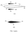
- Upper bifurcator vanes 5a are located on either side of the portion 11a. Both the portion 11a and the vanes have relatively rounded leading edges 25 and relatively sharp trailing edges 26, producing elongate, teardrop-shaped, longitudinal cross-sections which can help to reduce drag.
- Figure 1(d) shows schematically a view from above of a single bifurcator vane 5a, and illustrates an alternative shape for the longitudinal cross-sections, which although still substantially teardrop-shaped, has a relatively sharp leading edge.
- the chord of the bifurcator member 5a i.e. the distance between the leading and the trailing edge of the bifurcator member on a longitudinal cross-section containing the axial direction
- the corresponding width i.e. the width of the projected shape 6a at the longitudinal cross-section containing the chord
- the maximum width W 0 of the bifurcator vanes 5a should be less than 20% of the maximum chord C 0 of the vanes. This helps to reduce the drag caused by the presence of the vanes in the bypass duct. However, for mechanical stability reasons the maximum width W 0 can be greater than 10% of the maximum chord C 0 .
- the maximum width W 0 of the bifurcator vanes 5a is preferably less than 10% of the span H 0 of the vanes.
- the maximum chord C 0 can vary significantly. For example, typically it is greater than 10% of the span H 0 but less than 1.5 times the span.
- FIG 2 shows schematically a gas turbine engine having an arrangement of upper and lower bifurcator vanes 5b similar to the arrangements shown in Figures 1(a) and (b) .
- the projected shape comprises a first section 7 and a second section 9.
- the first section has a constant width and extends in a radial direction of the engine from the core fairing to a transition position 8 adjacent to the fan nacelle.
- the second section extends from the transition position in the same radial direction as the first section and has a width which rapidly increases with distance from the first section, such that the sides of the second section form outwardly concave curves.
- a projected shape is suitable for generating vortices (as indicated by arrows) in a region of the bypass duct adjacent to the fan nacelle.
- vortices are generated at the top centre and at the bottom centre of the bypass duct. These vortices may act to reduce the strength of the shear layer 10 and subsequently to reduce the strength of the interaction between the shear layer and the wing flaps of the aircraft, thereby lessening the installation noise of the aircraft.
- the vortices can be generated in a region of the bypass duct adjacent to the core fairing. This can improve mixing of the bypass and core flows.
- Figure 3(a) shows schematically an arrangement of upper and lower bifurcator vanes 5c similar to the arrangement of vanes 5a shown in Figures 1(a) and (b) .
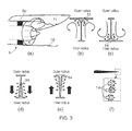
- Figures 3(b) to (e) show respective trailing edge views of the upper bifurcator vane of the engine (i.e. views along the axis of the bypass duct 4 from the downstream side of the vane).
- Figure 3(b) and (c) show bifurcator vanes having elongate projected shapes similar to that of the vane 5b shown in Figure 2 .
- Figure 3(d) and (e) show bifurcator vanes having projected shapes similar to that of the vane 5a shown in Figures 1(a) and (b) .
- the airflow from the discharge openings reduces the drag caused by the presence of the bifurcator vanes in the bypass duct.
- Figure 3(f) shows schematically detailed views on longitudinal cross-sections through the vane 5c of possible configurations for the trailing edge of the vane and the distribution of the discharge openings 14 around the trailing edge.
- Figure 4(a) shows schematically an engine having an arrangement of upper and lower bifurcator vanes 5d similar to those shown in Figures 1(a) and (b) .
- Figures 4(b) and (c) show respective leading edge views of the upper bifurcator vane of the engine (i.e. views along the axis of the bypass duct 4 from the upstream side of the vane), and
- Figures 4(d) and (e) show respective trailing edge views of the upper bifurcator vane of the engine.
- the vanes of Figures 4(b) and (c) have elongate projected shapes similar to that of the vane 5b shown in Figure 2 .
- the vanes of Figure 4(d) and (e) have elongate projected shapes similar to that of the vane 5a shown in Figures 1 (a) and (b) .
- one or more receiving openings 14 are formed at or adjacent the leading edge each bifurcator vane to receive an inflow of air from the bypass duct 4.
- One or more discharge openings 15, 15' are formed at or adjacent the trailing edge of the vane, the discharge openings being connected to the receiving openings by internal passages through the vanes.
- the vanes can have larger projected shapes, or more vanes can be provided in the duct, while still maintaining drag losses at an acceptable level. Further the flow of air through the vanes can enhance and reinforce the redistribution of the flow field around the bifurcator vane.
- the receiving 14 and discharge 15, 15' openings of Figures 4(b) to (e) have larger areas than the discharge openings of Figures 3(b) to (e) . This is to reduce frictional losses within the vanes 5d, and to encourage the diversion of duct air flow through the vanes.
- the vane 5d of Figure 4(e) has an annular discharge opening 15', which is linked to a corresponding annular receiving opening elsewhere on the surface of the bifurcator vane by an annular passage which conveys air between them. Annular openings may promote flow through the bifurcator vane.
- Figure 4(f) shows schematically four possible longitudinal cross-sections through the vane 5d, and illustrates the positions of the receiving 14 and discharge 15 openings around respectively the leading and trailing edges.
- the cross-sections are all substantially teardrop shaped.
- the first cross-section has the pointed end of the teardrop at the leading edge
- the second, third and fourth cross-sections have the pointed end of the teardrop at the trailing edge. While the configuration of the second, third and fourth cross-sections is normally the more aerodynamic, the diversion of air flow through the receiving and discharge openings can make the configuration of the first cross-section feasible.
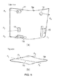
- Figure 5 shows schematically (a) a side view and (b) a top view of a bifurcator vane 5e having receiving 14 and discharge 15 openings located on a lateral side of the bifurcator vane.
- the openings can be rectangular or elliptical and are connected by internal passages. Connected receiving and discharge openings have different shapes and areas, thereby causing the velocity of the air flow through the passages to change between the receiving openings and the discharge openings.
- Figure 5(b) shows that the discharge openings may be located on the same lateral side of the bifurcator vane as the receiving opening to which it is connected, or they may be located on an opposing side so that one or more of the connecting passages 16 span the width of the bifurcator vane.
- the air pressures at the receiving openings (P 1 , P 2 , P 3 , P 6 , P 7 ) are higher than the air pressures at the discharge openings (P 4 , P 5 , P 8 , P 9 ). In this way, pressure gradients are established between the receiving and discharge openings and air flow in the regions around the receiving openings may be preferentially directed into the receiving openings. This effect may be used to increase the extent of the redirection of the air flow around the bifurcator vane.
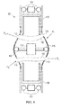
- Figure 6 shows schematically a plan view of a bifurcator vane 5f having an actuator system for opening or closing receiving 14 and discharge 15 openings on its surface.
- the opposing surfaces 18 of the bifurcator vane are moveable and deformable by the extension and retraction of actuator 17, the surfaces being supported on rollers 20, as explained in US2008/0166227A1 .
- portions of the surfaces forming the openings are contained in housings 19.
- the opposing surfaces bulge outwardly, exposing more surface portions outside the housings, including those portions forming the openings.
- Respective passages 16 connecting pairs of receiving and discharge openings from P 1 to P 2 and from P 3 to P 4 can simply be the hollow interior of the bifurcator vane. If necessary, an internal dividing wall (e.g. at least partly formed by the actuator) can ensure that air flows from P 1 only to P 2 and from P 3 only to P 4 .
- This system may be used to vary the amount of air blowing through the bifurcator vane at different stages of a flight, for example during take off or cruising at altitude.
- FIG. 7 shows schematically bifurcator vanes 5g, 5h in different positions and orientations within the bypass duct 4 of a gas turbine engine 1 in (a) a perspective view and (b) a cross-sectional view through the duct.
- Bifurcator vanes can extend, for example, between the fan nacelle 2 and the core fairing 3 in non-radial 5g and radial 5h directions of the engine, between the fan nacelle and the attachment pylon 11, and between two different positions on the fan nacelle.
- the placement of the bifurcator vanes within the bypass duct may be influenced by structural, mechanical and aerodynamic requirements.
- An advantage of having a bifurcator vane extending in a non-radial direction of the engine 1 is that it facilitates circumferential deflection of the air flow as well as radial deflection. This may make it possible, for example, to direct air flow towards or away from the attachment pylon 11.
- Figures 7(c) to (e) show respective views, along the axis of the duct, of non-radial bifurcator vanes, and illustrate possible projected shapes 6c, 6d for the vanes.
- the shapes 6c of Figures 7(c) and (d) are similar to the shapes 6a discussed above in relation to Figure 1 , the width of the shapes increasing uniformly with distance from one end to the other. Due to the pressure variations which this width variation induces, the air flow is deflected from the thinner end of the shapes towards the thicker end of the shapes.
- the shape 6d of Figure 7(e) has a width which increases from both ends of the shape towards a position of maximum width between the ends. With such a projected shape, the air flow around the bifurcator vane is deflected from the thinner ends of the projected shape towards the position of maximum width.
- Figure 8 shows schematically (a) a perspective view and (b) a cross-sectional view of a gas turbine engine having an arrangement in which two bifurcator vanes 5i are positioned in the bypass duct 4 to extend between the fan nacelle 2 and the attachment pylon 11.
- the bifurcator vanes may deflect air towards or away from the pylon. Similar effects may instead be achieved by having bifurcator vanes extending between the core fairing 3 and the pylon.
- the extent of recirculation of air occurring around the trailing end of the pylon may be limited. Additionally, the strength of the shear layer 10 in this region may be reduced, thereby leading to a reduction in the engine noise.
Landscapes
- Engineering & Computer Science (AREA)
- Mechanical Engineering (AREA)
- Chemical & Material Sciences (AREA)
- Combustion & Propulsion (AREA)
- General Engineering & Computer Science (AREA)
- Aviation & Aerospace Engineering (AREA)
- Structures Of Non-Positive Displacement Pumps (AREA)
Priority Applications (2)
| Application Number | Priority Date | Filing Date | Title |
|---|---|---|---|
| EP14185490.1A EP2846006A1 (fr) | 2010-04-30 | 2011-04-15 | Moteur à turbine à gaz |
| EP14185491.9A EP2846007A1 (fr) | 2010-04-30 | 2011-04-15 | Moteur à turbine à gaz |
Applications Claiming Priority (1)
| Application Number | Priority Date | Filing Date | Title |
|---|---|---|---|
| GB201007215A GB201007215D0 (en) | 2010-04-30 | 2010-04-30 | Gas turbine engine |
Related Child Applications (2)
| Application Number | Title | Priority Date | Filing Date |
|---|---|---|---|
| EP14185490.1A Division EP2846006A1 (fr) | 2010-04-30 | 2011-04-15 | Moteur à turbine à gaz |
| EP14185491.9A Division EP2846007A1 (fr) | 2010-04-30 | 2011-04-15 | Moteur à turbine à gaz |
Publications (2)
| Publication Number | Publication Date |
|---|---|
| EP2383442A2 true EP2383442A2 (fr) | 2011-11-02 |
| EP2383442A3 EP2383442A3 (fr) | 2014-04-02 |
Family
ID=42289863
Family Applications (3)
| Application Number | Title | Priority Date | Filing Date |
|---|---|---|---|
| EP14185490.1A Withdrawn EP2846006A1 (fr) | 2010-04-30 | 2011-04-15 | Moteur à turbine à gaz |
| EP11162565.3A Withdrawn EP2383442A3 (fr) | 2010-04-30 | 2011-04-15 | Moteur à turbine à gaz |
| EP14185491.9A Withdrawn EP2846007A1 (fr) | 2010-04-30 | 2011-04-15 | Moteur à turbine à gaz |
Family Applications Before (1)
| Application Number | Title | Priority Date | Filing Date |
|---|---|---|---|
| EP14185490.1A Withdrawn EP2846006A1 (fr) | 2010-04-30 | 2011-04-15 | Moteur à turbine à gaz |
Family Applications After (1)
| Application Number | Title | Priority Date | Filing Date |
|---|---|---|---|
| EP14185491.9A Withdrawn EP2846007A1 (fr) | 2010-04-30 | 2011-04-15 | Moteur à turbine à gaz |
Country Status (3)
| Country | Link |
|---|---|
| US (1) | US8870530B2 (fr) |
| EP (3) | EP2846006A1 (fr) |
| GB (1) | GB201007215D0 (fr) |
Families Citing this family (7)
| Publication number | Priority date | Publication date | Assignee | Title |
|---|---|---|---|---|
| US20110110763A1 (en) * | 2009-11-06 | 2011-05-12 | Dresser-Rand Company | Exhaust Ring and Method to Reduce Turbine Acoustic Signature |
| US10060390B2 (en) | 2012-02-29 | 2018-08-28 | United Technologies Corporation | Bypass duct with angled drag links |
| JP6035946B2 (ja) * | 2012-07-26 | 2016-11-30 | 株式会社Ihi | エンジンダクト及び航空機エンジン |
| US10309236B2 (en) * | 2013-03-14 | 2019-06-04 | Rolls-Royce Corporation | Subsonic shock strut |
| US10227896B2 (en) | 2016-03-17 | 2019-03-12 | Rolls-Royce Corporation | Flow segregator for infrared exhaust suppressor |
| US10759541B2 (en) * | 2016-10-14 | 2020-09-01 | Rohr, Inc. | Nacelle bifurcation with leading edge structure |
| WO2021138538A1 (fr) * | 2020-01-03 | 2021-07-08 | University Of Kansas | Procédés et systèmes d'atténuation du bruit de jet à grande vitesse |
Citations (8)
| Publication number | Priority date | Publication date | Assignee | Title |
|---|---|---|---|---|
| US6139259A (en) * | 1998-10-29 | 2000-10-31 | General Electric Company | Low noise permeable airfoil |
| US6502383B1 (en) | 2000-08-31 | 2003-01-07 | General Electric Company | Stub airfoil exhaust nozzle |
| US6820410B2 (en) | 2002-05-21 | 2004-11-23 | The Nordam Group, Inc. | Bifurcated turbofan nozzle |
| WO2008045064A1 (fr) | 2006-10-12 | 2008-04-17 | United Technologies Corporation | Système et procédé de contrôle de bruit de moteur à double flux |
| WO2008045091A1 (fr) | 2006-10-12 | 2008-04-17 | United Technologies Corporation | Buse à section variable d'un ventilateur de turbine à gaz équipée d'un système à pièces rapportées pivotantes |
| EP1936172A2 (fr) | 2006-12-06 | 2008-06-25 | The Boeing Company | Systèmes et procédés pour diriger passivement les flux de tuyère de moteur d'un avion |
| US20080166227A1 (en) | 2007-01-06 | 2008-07-10 | Rolls-Royce Plc | Nozzle assembly |
| US7472543B2 (en) | 2002-03-20 | 2009-01-06 | The Regents Of The University Of California | Jet engine noise suppressor |
Family Cites Families (23)
| Publication number | Priority date | Publication date | Assignee | Title |
|---|---|---|---|---|
| US3137131A (en) | 1961-09-18 | 1964-06-16 | United Aircraft Corp | Noise suppression of fan engines |
| US3540682A (en) * | 1964-12-02 | 1970-11-17 | Gen Electric | Turbofan type engine frame and support system |
| FR2139741B1 (fr) | 1971-06-03 | 1975-01-17 | Snecma | |
| US4244440A (en) | 1978-12-01 | 1981-01-13 | General Electric Company | Apparatus for suppressing internally generated gas turbine engine low frequency noise |
| US5369954A (en) * | 1991-04-22 | 1994-12-06 | General Electric Company | Turbofan engine bypass and exhaust system |
| US6308553B1 (en) * | 1999-06-04 | 2001-10-30 | Honeywell International Inc | Self-normalizing flow sensor and method for the same |
| US6353789B1 (en) * | 1999-12-13 | 2002-03-05 | United Technologies Corporation | Predicting broadband noise from a stator vane of a gas turbine engine |
| US6439840B1 (en) * | 2000-11-30 | 2002-08-27 | Pratt & Whitney Canada Corp. | Bypass duct fan noise reduction assembly |
| FR2858999B1 (fr) | 2003-08-18 | 2005-11-11 | Snecma Moteurs | Turbomachine pour aeronef a emissions de bruit reduites |
| DE10357075B4 (de) | 2003-12-06 | 2006-01-12 | Dornier Gmbh | Verfahren zur Lärmreduzierung von Turbomaschinen |
| DE102006015727A1 (de) | 2006-02-25 | 2007-09-06 | Airbus Deutschland Gmbh | Verkleidungskörper der Klappenkinematik am Flügel eines Flugzeuges |
| US7455498B2 (en) * | 2006-06-19 | 2008-11-25 | United Technologies Corporation | Slotted bleed deflector for a gas turbine engine |
| FR2903076B1 (fr) * | 2006-06-30 | 2009-05-29 | Aircelle Sa | Nacelle structurante |
| US7765788B2 (en) * | 2006-07-06 | 2010-08-03 | United Technologies Corporation | Cooling exchanger duct |
| US7900433B2 (en) * | 2006-08-31 | 2011-03-08 | United Technologies Corporation | Fan exhaust nozzle for turbofan engine |
| FR2905734B1 (fr) * | 2006-09-07 | 2012-07-13 | Airbus France | Dispositif permettant d'ameliorer l'efficacite des traitements acoustiques dans un conduit d'une motorisation d'aeronef |
| FR2905990A1 (fr) * | 2006-09-20 | 2008-03-21 | Snecma Sa | Systeme propulsif a pylone integre pour avion. |
| US8418471B2 (en) * | 2006-10-12 | 2013-04-16 | United Technologies Corporation | Gas turbine engine having variable flow through a bifurcation having an intake with multiple louvers |
| WO2008045053A2 (fr) | 2006-10-12 | 2008-04-17 | United Technologies Corporation | Actionnement d'une bifurcation de moteur à réacteur à double flux pour modifier une zone effective de sortie de tuyère |
| GB0624118D0 (en) | 2006-12-02 | 2007-01-10 | Rolls Royce Plc | Seal arrangement |
| FR2917714B1 (fr) | 2007-06-25 | 2009-11-27 | Airbus France | Turboreacteur pour aeronef |
| US8784051B2 (en) * | 2008-06-30 | 2014-07-22 | Pratt & Whitney Canada Corp. | Strut for a gas turbine engine |
| EP2427634B1 (fr) * | 2009-05-07 | 2018-04-11 | GKN Aerospace Sweden AB | Support et structure de turbine à gaz comprenant ledit support |
-
2010
- 2010-04-30 GB GB201007215A patent/GB201007215D0/en not_active Ceased
-
2011
- 2011-04-15 EP EP14185490.1A patent/EP2846006A1/fr not_active Withdrawn
- 2011-04-15 EP EP11162565.3A patent/EP2383442A3/fr not_active Withdrawn
- 2011-04-15 EP EP14185491.9A patent/EP2846007A1/fr not_active Withdrawn
- 2011-04-15 US US13/087,870 patent/US8870530B2/en not_active Expired - Fee Related
Patent Citations (8)
| Publication number | Priority date | Publication date | Assignee | Title |
|---|---|---|---|---|
| US6139259A (en) * | 1998-10-29 | 2000-10-31 | General Electric Company | Low noise permeable airfoil |
| US6502383B1 (en) | 2000-08-31 | 2003-01-07 | General Electric Company | Stub airfoil exhaust nozzle |
| US7472543B2 (en) | 2002-03-20 | 2009-01-06 | The Regents Of The University Of California | Jet engine noise suppressor |
| US6820410B2 (en) | 2002-05-21 | 2004-11-23 | The Nordam Group, Inc. | Bifurcated turbofan nozzle |
| WO2008045064A1 (fr) | 2006-10-12 | 2008-04-17 | United Technologies Corporation | Système et procédé de contrôle de bruit de moteur à double flux |
| WO2008045091A1 (fr) | 2006-10-12 | 2008-04-17 | United Technologies Corporation | Buse à section variable d'un ventilateur de turbine à gaz équipée d'un système à pièces rapportées pivotantes |
| EP1936172A2 (fr) | 2006-12-06 | 2008-06-25 | The Boeing Company | Systèmes et procédés pour diriger passivement les flux de tuyère de moteur d'un avion |
| US20080166227A1 (en) | 2007-01-06 | 2008-07-10 | Rolls-Royce Plc | Nozzle assembly |
Also Published As
| Publication number | Publication date |
|---|---|
| EP2846006A1 (fr) | 2015-03-11 |
| GB201007215D0 (en) | 2010-06-16 |
| EP2846007A1 (fr) | 2015-03-11 |
| US20110268560A1 (en) | 2011-11-03 |
| US8870530B2 (en) | 2014-10-28 |
| EP2383442A3 (fr) | 2014-04-02 |
Similar Documents
| Publication | Publication Date | Title |
|---|---|---|
| US8870530B2 (en) | Gas turbine engine | |
| EP1936172B1 (fr) | Systèmes et procédés pour diriger passivement les flux de tuyère de moteur d'un avion | |
| EP2460978B1 (fr) | Aube de guidage à géométrie variable | |
| US9010680B2 (en) | Pylon for attaching a gas turbine engine | |
| US8821123B2 (en) | Double-ducted fan | |
| CN103625635B (zh) | 具有表面、前缘和主动气流控制系统的气流装置及其交通工具 | |
| US4505443A (en) | Propulsion system for a V/STOL airplane | |
| EP1895140B1 (fr) | Buse d'échappement de Soufflante pour turboréacteur à double flux | |
| US20180065727A1 (en) | Aircraft propulsion unit comprising an unducted-fan turbine engine and an attachment pylon | |
| RU2607715C2 (ru) | Пилон подвески для газотурбинного двигателя | |
| EP2402251A2 (fr) | Installation de turboréacteur | |
| CN102947175A (zh) | 飞机的高升力系统 | |
| CN104040117A (zh) | 具有齿轮传动架构的燃气涡轮发动机 | |
| EP3483395B1 (fr) | Conduits inter-turbine comportant des mécanismes de régulation d'écoulement | |
| CN104011358A (zh) | 具有低风扇压力比的燃气涡轮发动机 | |
| CN109996721B (zh) | 具有后发动机的飞行器 | |
| CN101297107B (zh) | 用于短距起落航空器的涡轮风扇发动机 | |
| EP3604125A1 (fr) | Corps d'écoulement d'un aéronef et aéronef | |
| EP1923310A2 (fr) | Dispositif de réduction de traînée de nacelle pour moteur de turbine à gaz à double flux | |
| EP3265662B1 (fr) | Ensemble échappement de turbine à gaz | |
| CN113753221B (zh) | 一种机翼增升系统 | |
| EP2918777A1 (fr) | Aube d'atténuation de bruit |
Legal Events
| Date | Code | Title | Description |
|---|---|---|---|
| AK | Designated contracting states |
Kind code of ref document: A2 Designated state(s): AL AT BE BG CH CY CZ DE DK EE ES FI FR GB GR HR HU IE IS IT LI LT LU LV MC MK MT NL NO PL PT RO RS SE SI SK SM TR |
|
| AX | Request for extension of the european patent |
Extension state: BA ME |
|
| PUAI | Public reference made under article 153(3) epc to a published international application that has entered the european phase |
Free format text: ORIGINAL CODE: 0009012 |
|
| RIC1 | Information provided on ipc code assigned before grant |
Ipc: B64D 29/06 20060101ALI20131108BHEP Ipc: F01D 25/16 20060101AFI20131108BHEP Ipc: F02C 7/20 20060101ALI20131108BHEP Ipc: F02K 3/06 20060101ALI20131108BHEP Ipc: F01D 25/28 20060101ALI20131108BHEP Ipc: B64D 27/18 20060101ALI20131108BHEP |
|
| PUAL | Search report despatched |
Free format text: ORIGINAL CODE: 0009013 |
|
| AK | Designated contracting states |
Kind code of ref document: A3 Designated state(s): AL AT BE BG CH CY CZ DE DK EE ES FI FR GB GR HR HU IE IS IT LI LT LU LV MC MK MT NL NO PL PT RO RS SE SI SK SM TR |
|
| AX | Request for extension of the european patent |
Extension state: BA ME |
|
| RIC1 | Information provided on ipc code assigned before grant |
Ipc: F02C 7/20 20060101ALI20140225BHEP Ipc: F01D 25/28 20060101ALI20140225BHEP Ipc: F01D 25/16 20060101AFI20140225BHEP Ipc: B64D 27/18 20060101ALI20140225BHEP Ipc: F02K 3/06 20060101ALI20140225BHEP Ipc: B64D 29/06 20060101ALI20140225BHEP |
|
| 17P | Request for examination filed |
Effective date: 20140918 |
|
| RBV | Designated contracting states (corrected) |
Designated state(s): AL AT BE BG CH CY CZ DE DK EE ES FI FR GB GR HR HU IE IS IT LI LT LU LV MC MK MT NL NO PL PT RO RS SE SI SK SM TR |
|
| RAP1 | Party data changed (applicant data changed or rights of an application transferred) |
Owner name: ROLLS-ROYCE PLC |
|
| STAA | Information on the status of an ep patent application or granted ep patent |
Free format text: STATUS: EXAMINATION IS IN PROGRESS |
|
| 17Q | First examination report despatched |
Effective date: 20190503 |
|
| STAA | Information on the status of an ep patent application or granted ep patent |
Free format text: STATUS: THE APPLICATION HAS BEEN WITHDRAWN |
|
| 18W | Application withdrawn |
Effective date: 20190902 |