EP2383479A2 - Palier à aiguilles avec cage à fenêtres comprenant des éléments de retention aux barettes et deux aiguilles dans chaque alvéole de la cage - Google Patents
Palier à aiguilles avec cage à fenêtres comprenant des éléments de retention aux barettes et deux aiguilles dans chaque alvéole de la cage Download PDFInfo
- Publication number
- EP2383479A2 EP2383479A2 EP11157778A EP11157778A EP2383479A2 EP 2383479 A2 EP2383479 A2 EP 2383479A2 EP 11157778 A EP11157778 A EP 11157778A EP 11157778 A EP11157778 A EP 11157778A EP 2383479 A2 EP2383479 A2 EP 2383479A2
- Authority
- EP
- European Patent Office
- Prior art keywords
- cage
- needle
- needles
- facing
- Prior art date
- Legal status (The legal status is an assumption and is not a legal conclusion. Google has not performed a legal analysis and makes no representation as to the accuracy of the status listed.)
- Withdrawn
Links
Images
Classifications
-
- F—MECHANICAL ENGINEERING; LIGHTING; HEATING; WEAPONS; BLASTING
- F16—ENGINEERING ELEMENTS AND UNITS; GENERAL MEASURES FOR PRODUCING AND MAINTAINING EFFECTIVE FUNCTIONING OF MACHINES OR INSTALLATIONS; THERMAL INSULATION IN GENERAL
- F16C—SHAFTS; FLEXIBLE SHAFTS; ELEMENTS OR CRANKSHAFT MECHANISMS; ROTARY BODIES OTHER THAN GEARING ELEMENTS; BEARINGS
- F16C33/00—Parts of bearings; Special methods for making bearings or parts thereof
- F16C33/30—Parts of ball or roller bearings
- F16C33/46—Cages for rollers or needles
- F16C33/467—Details of individual pockets, e.g. shape or roller retaining means
- F16C33/4676—Details of individual pockets, e.g. shape or roller retaining means of the stays separating adjacent cage pockets, e.g. guide means for the bearing-surface of the rollers
-
- F—MECHANICAL ENGINEERING; LIGHTING; HEATING; WEAPONS; BLASTING
- F16—ENGINEERING ELEMENTS AND UNITS; GENERAL MEASURES FOR PRODUCING AND MAINTAINING EFFECTIVE FUNCTIONING OF MACHINES OR INSTALLATIONS; THERMAL INSULATION IN GENERAL
- F16C—SHAFTS; FLEXIBLE SHAFTS; ELEMENTS OR CRANKSHAFT MECHANISMS; ROTARY BODIES OTHER THAN GEARING ELEMENTS; BEARINGS
- F16C19/00—Bearings with rolling contact, for exclusively rotary movement
- F16C19/22—Bearings with rolling contact, for exclusively rotary movement with bearing rollers essentially of the same size in one or more circular rows, e.g. needle bearings
- F16C19/44—Needle bearings
- F16C19/46—Needle bearings with one row or needles
- F16C19/463—Needle bearings with one row or needles consisting of needle rollers held in a cage, i.e. subunit without race rings
-
- F—MECHANICAL ENGINEERING; LIGHTING; HEATING; WEAPONS; BLASTING
- F16—ENGINEERING ELEMENTS AND UNITS; GENERAL MEASURES FOR PRODUCING AND MAINTAINING EFFECTIVE FUNCTIONING OF MACHINES OR INSTALLATIONS; THERMAL INSULATION IN GENERAL
- F16C—SHAFTS; FLEXIBLE SHAFTS; ELEMENTS OR CRANKSHAFT MECHANISMS; ROTARY BODIES OTHER THAN GEARING ELEMENTS; BEARINGS
- F16C33/00—Parts of bearings; Special methods for making bearings or parts thereof
- F16C33/30—Parts of ball or roller bearings
- F16C33/46—Cages for rollers or needles
- F16C33/4617—Massive or moulded cages having cage pockets surrounding the rollers, e.g. machined window cages
- F16C33/4623—Massive or moulded cages having cage pockets surrounding the rollers, e.g. machined window cages formed as one-piece cages, i.e. monoblock cages
- F16C33/4635—Massive or moulded cages having cage pockets surrounding the rollers, e.g. machined window cages formed as one-piece cages, i.e. monoblock cages made from plastic, e.g. injection moulded window cages
-
- F—MECHANICAL ENGINEERING; LIGHTING; HEATING; WEAPONS; BLASTING
- F16—ENGINEERING ELEMENTS AND UNITS; GENERAL MEASURES FOR PRODUCING AND MAINTAINING EFFECTIVE FUNCTIONING OF MACHINES OR INSTALLATIONS; THERMAL INSULATION IN GENERAL
- F16C—SHAFTS; FLEXIBLE SHAFTS; ELEMENTS OR CRANKSHAFT MECHANISMS; ROTARY BODIES OTHER THAN GEARING ELEMENTS; BEARINGS
- F16C9/00—Bearings for crankshafts or connecting-rods; Attachment of connecting-rods
- F16C9/04—Connecting-rod bearings; Attachments thereof
Definitions
- the invention relates to a needle bearing with a cage in which between two side rings of the cage and the side rings connecting webs of the cage cage pockets are formed for receiving needles, wherein in at least one of the cage pockets of the cage two needles are arranged directly adjacent to each other, wherein holding elements are present with which the needles are held in the radial direction in the cage pocket, wherein the holding elements are formed as arranged on the web and extending in the circumferential direction projections, wherein the projections extend over the entire axial width of the cage pocket.
- a needle bearing of this kind reveals the DE 1 886 747 U
- Similar solutions show the GB 752 854 A that DE 1 009 445 B and the US Pat. No. 3,382,016
- a similar needle roller bearing is for example in the CH 338 655 described.
- the needle bearing here has a cage in which per cage pocket two needles are arranged. This has advantages, for example, if a component has to be mounted pivotably about relatively small pivoting angles, wherein the pivoting movement takes place as a reciprocating movement, as is typical for example for the storage of a connecting rod. So that the needles can not fall out of the cage, the cage webs in the latter document at two axially spaced locations nose-like projections, which act as holding elements.
- the invention is therefore based on the object , a needle bearing of the type mentioned in such a way that the explained disadvantages are reduced or eliminated. Accordingly, the needle bearing and in particular its cage should be produced in a simple and cost-effective manner, in particular by Spritzgie- ⁇ en. The wear of the bearing should be reduced. In particular, oscillating movements and shock loads are to be improved. Finally, the needle bearing should be characterized by a quieter run.
- a needle-facing surface of a holding element has a planar shape, wherein the holding element, starting from a pitch circle of the needle bearing extends radially outwardly, wherein a needle facing a second surface of the The surface normal of the needle-facing surface of the holding member and the surface normal of the needle-facing second surface of the web enclose an angle which is between 20 ° and 40 °, and wherein the a needle-facing second surface merges in its radially inner region in a third surface which is formed so that the cage pocket widens in the circumferential direction.
- the needle-facing second surface of the web may in particular have a surface normal, which in the circumferential direction (ie tangential) has or with this direction forms an angle between 0 ° and 10 °.
- the third surface may be flat. It is preferably provided that the third surface to the radial direction forms an angle between 15 ° and 45 °.
- the cage is preferably made of plastic.
- the holding elements extend in the proposed solution over the entire width of the receiving pocket, seen in the axial direction.
- the bearing surface of the holding elements is substantially increased compared to previously known solution. Accordingly, the specific load of the holding elements is clear lower, resulting in reduced wear. This is particularly noticeable in oscillating applications, for example in a conrod bearing, for which the invention is particularly well suited.
- the proposed geometry of the projections serving as holding elements prevents falling out of the needles from the cage pockets. This results in a self-holding effect of the needles in the cage pockets.
- the geometry of the projections in relation to the receiving space of a cage pocket is chosen so that the outlet of a needle overlapping of the two adjacent needles would be required. Since this can not take place, the needles are secured in the assembled state of the bearing assembly in the cage pocket.
- the maximum Käfigtaschensch is therefore smaller than the sum of the two WälzMech devismesser; it creates an excess (overlap) and so the self-holding effect.
- the design of the needle bearing is preferably carried out so that the distance between two adjacent needles in a cage pocket (resulting from the WälzISE tomessern) is chosen so that it is smaller than the resulting due to the oscillating swing angle Abrollweg a needle on the track (covered path of the rolling element on the track).
- the overrun of lubricant deposits and thus the distribution of the same are thus by tuning the Wälz emotions tomessers and the path to be traveled of the rolling element determined on its career.
- a too low load rating and too high contact voltages are eliminated by increasing the number of rolling elements in the camp.
- a cage with two rolling elements per cage pocket is used.
- the noise level is reduced and space created for the lubricating medium in the cage.
- the self-holding arrangement also results in an advantageous manner a simplification of the assembly. There are no mounting sleeves and fixtures required. As a result, the handling is simplified and thus achieved a cost reduction during assembly.
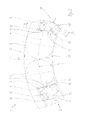
- a needle bearing 1 and its cage 2 can be seen.
- the bearing outer ring and the bearing inner ring are in Fig. 1 only indicated, wherein the outer ring raceway 16 and the inner ring raceway 17 can be seen.
- the outer and / or inner rings are often formed by running surfaces on components to be stored.
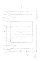
- the cage 2 has a classic design. He has two side rings 3 and 4 (s. Fig. 2 ), which are connected to each other via a number of webs 5. Between the side rings 3, 4 and the webs 5 cage pockets 6 are accordingly formed.
- each cage pocket 6 in the present case two needles 7 and 8 are arranged, as shown for a cage pocket 6 in the two figures.
- the needles 7, 8 does not fall out of the cage pocket 6 radially outward, holding elements 9 and 10 are integrally formed on the webs 5, as best in Fig. 1 can be seen. How to turn it in Fig. 2 can be seen, the holding elements 9, 10 extend over the entire axial width b of the cage pocket. 6
- the surface 11, which forms the holding element 9, 10 on its side facing the needle 7, 8, is flat in the exemplary embodiment. It extends from the radially outer end of the holding element 9, 10 radially inwardly to a pitch circle 12, which has a pitch circle diameter D T.
- the two opposing surfaces 11 of a cage pocket 6 are arranged parallel to each other in the embodiment.
- the surface 11 is adjoined radially inwardly-starting at the partial force 12-by a second, likewise flat surface 13, which runs essentially in the radial direction r. Accordingly, a surface normal 14 (see FIG. Fig. 1 ) on the second surface 13 in the circumferential direction U.
- the surface normal may also include a small angle with the circumferential direction U, which is smaller than 10 °.
- the surface normal of a needle 7, 8 facing surface 11 of the support member 9, 10 and the surface normal of a needle 7, 8 facing the second surface 13 of the web 5 a Include angle ⁇ , which is between 20 ° and 40 °, preferably between 25 ° and 35 °. This angle is in Fig. 1 entered.
- the second surface 13 transitions into a third, again flat surface 15. As in Fig. 1 can be seen, this surface 15 extends at an angle ⁇ to the radial direction r.
- the angle ⁇ is in the exemplary embodiment about 30 °.
Landscapes
- Engineering & Computer Science (AREA)
- General Engineering & Computer Science (AREA)
- Mechanical Engineering (AREA)
- Rolling Contact Bearings (AREA)
Applications Claiming Priority (1)
| Application Number | Priority Date | Filing Date | Title |
|---|---|---|---|
| DE102010013629A DE102010013629B4 (de) | 2010-04-01 | 2010-04-01 | Nadellager |
Publications (1)
| Publication Number | Publication Date |
|---|---|
| EP2383479A2 true EP2383479A2 (fr) | 2011-11-02 |
Family
ID=44333074
Family Applications (1)
| Application Number | Title | Priority Date | Filing Date |
|---|---|---|---|
| EP11157778A Withdrawn EP2383479A2 (fr) | 2010-04-01 | 2011-03-11 | Palier à aiguilles avec cage à fenêtres comprenant des éléments de retention aux barettes et deux aiguilles dans chaque alvéole de la cage |
Country Status (2)
| Country | Link |
|---|---|
| EP (1) | EP2383479A2 (fr) |
| DE (1) | DE102010013629B4 (fr) |
Citations (7)
| Publication number | Priority date | Publication date | Assignee | Title |
|---|---|---|---|---|
| GB752854A (en) | 1953-06-13 | 1956-07-18 | Schaeffler Wilhelm | Cage for roller bearings, more particularly needle bearings |
| US2772128A (en) | 1953-06-13 | 1956-11-27 | Ind Schaeffier | Cage for needle bearings |
| DE1009445B (de) | 1954-03-25 | 1957-05-29 | Schaeffler Ohg Industriewerk | Nadellager |
| CH338655A (fr) | 1954-07-20 | 1959-05-31 | Pitner Alfred | Palier à roulement |
| DE1886747U (de) | 1963-05-02 | 1964-01-30 | Schaeffler Ohg Industriewerk | Waelzlager mit in einem kaefig gefuehrten zylindrischen waelzkoerpern. |
| US3382016A (en) | 1965-11-01 | 1968-05-07 | Roller Bearing Co Of America | Arrangement of tandem rollers in a roller bearing and method of assembling same |
| DE3543364A1 (de) | 1985-12-07 | 1987-06-11 | Schaeffler Waelzlager Kg | Radial-waelzlagerkaefig fuer zylindrische waelzkoerper |
Family Cites Families (2)
| Publication number | Priority date | Publication date | Assignee | Title |
|---|---|---|---|---|
| US3543364A (en) * | 1968-08-30 | 1970-12-01 | James Mackew | Tool bit holder |
| DE19754836A1 (de) * | 1997-12-10 | 1999-06-17 | Schaeffler Waelzlager Ohg | Nadellagerkäfig und Verfahren zu seiner Herstellung |
-
2010
- 2010-04-01 DE DE102010013629A patent/DE102010013629B4/de not_active Expired - Fee Related
-
2011
- 2011-03-11 EP EP11157778A patent/EP2383479A2/fr not_active Withdrawn
Patent Citations (7)
| Publication number | Priority date | Publication date | Assignee | Title |
|---|---|---|---|---|
| GB752854A (en) | 1953-06-13 | 1956-07-18 | Schaeffler Wilhelm | Cage for roller bearings, more particularly needle bearings |
| US2772128A (en) | 1953-06-13 | 1956-11-27 | Ind Schaeffier | Cage for needle bearings |
| DE1009445B (de) | 1954-03-25 | 1957-05-29 | Schaeffler Ohg Industriewerk | Nadellager |
| CH338655A (fr) | 1954-07-20 | 1959-05-31 | Pitner Alfred | Palier à roulement |
| DE1886747U (de) | 1963-05-02 | 1964-01-30 | Schaeffler Ohg Industriewerk | Waelzlager mit in einem kaefig gefuehrten zylindrischen waelzkoerpern. |
| US3382016A (en) | 1965-11-01 | 1968-05-07 | Roller Bearing Co Of America | Arrangement of tandem rollers in a roller bearing and method of assembling same |
| DE3543364A1 (de) | 1985-12-07 | 1987-06-11 | Schaeffler Waelzlager Kg | Radial-waelzlagerkaefig fuer zylindrische waelzkoerper |
Also Published As
| Publication number | Publication date |
|---|---|
| DE102010013629B4 (de) | 2012-04-19 |
| DE102010013629A1 (de) | 2011-10-06 |
Similar Documents
| Publication | Publication Date | Title |
|---|---|---|
| DE102009006859B3 (de) | Wälzlagerkäfig | |
| WO2010063258A1 (fr) | Cage en forme de peigne pour un palier à roulement, en particulier cage double en forme de peigne pour un roulement à rouleaux cylindriques, palier à roulement et procédé pour produire une cage en forme de peigne pour un palier à roulement | |
| DE102011004374A1 (de) | Lagerkäfigsegment, Lagerkäfig und Verfahren zur Herstellung desselben | |
| DE102010007706A1 (de) | Lagerkombination zur radialen und axialen Abstützung insbesondere für ein Los- oder Zwischenrad in einem Getriebe | |
| DE102012206376B3 (de) | Schrägkugellager | |
| WO2021069008A1 (fr) | Cage de roulement en deux parties et palier de roulement doté d'un telle cage de roulement | |
| DE102013218434B4 (de) | Lagerung | |
| DE102005059033A1 (de) | Radialwälzlager, insbesondere einreihiges Rillenwälzlager | |
| DE10355363A1 (de) | Lageranordnung | |
| DE102012212056A1 (de) | Käfig für Schrägkugellager | |
| DE102014215073B4 (de) | Adapter sowie Lagereinheit und Radlager mit dem Adapter | |
| WO2013087276A1 (fr) | Palier à roulement | |
| DE102008004033A1 (de) | Käfig für Wälzkörper | |
| DE4112506C2 (de) | Wälzlagerkäfig | |
| DE102010046270A1 (de) | Rollenlager | |
| DE102008004046A1 (de) | Käfig für Wälzkörper | |
| DE102010013629B4 (de) | Nadellager | |
| DE102008062913A1 (de) | Segmentkäfig | |
| DE102015223510A1 (de) | Wälzlagerkäfig | |
| DE102013215204A1 (de) | Geteilter Wälzkörperkäfig aus Kunststoff | |
| DE102013221600A1 (de) | Radialgelenklager | |
| DE102014223164B4 (de) | Dichtungsführungseinheit | |
| DE102010014482A1 (de) | Wälzlager | |
| DE102016222711A1 (de) | Kegelrollenlager | |
| DE102009050524A1 (de) | Radial-Rollenwälzlager |
Legal Events
| Date | Code | Title | Description |
|---|---|---|---|
| AK | Designated contracting states |
Kind code of ref document: A2 Designated state(s): AL AT BE BG CH CY CZ DE DK EE ES FI FR GB GR HR HU IE IS IT LI LT LU LV MC MK MT NL NO PL PT RO RS SE SI SK SM TR |
|
| AX | Request for extension of the european patent |
Extension state: BA ME |
|
| PUAI | Public reference made under article 153(3) epc to a published international application that has entered the european phase |
Free format text: ORIGINAL CODE: 0009012 |
|
| STAA | Information on the status of an ep patent application or granted ep patent |
Free format text: STATUS: THE APPLICATION IS DEEMED TO BE WITHDRAWN |
|
| 18D | Application deemed to be withdrawn |
Effective date: 20151001 |