EP2383523B1 - Heizungsanlage zur Warmwasserproduktion in einem Haushalt - Google Patents
Heizungsanlage zur Warmwasserproduktion in einem Haushalt Download PDFInfo
- Publication number
- EP2383523B1 EP2383523B1 EP10305468A EP10305468A EP2383523B1 EP 2383523 B1 EP2383523 B1 EP 2383523B1 EP 10305468 A EP10305468 A EP 10305468A EP 10305468 A EP10305468 A EP 10305468A EP 2383523 B1 EP2383523 B1 EP 2383523B1
- Authority
- EP
- European Patent Office
- Prior art keywords
- fluid
- source
- heat energy
- plant
- energy production
- Prior art date
- Legal status (The legal status is an assumption and is not a legal conclusion. Google has not performed a legal analysis and makes no representation as to the accuracy of the status listed.)
- Not-in-force
Links
Images





Classifications
-
- F—MECHANICAL ENGINEERING; LIGHTING; HEATING; WEAPONS; BLASTING
- F24—HEATING; RANGES; VENTILATING
- F24D—DOMESTIC- OR SPACE-HEATING SYSTEMS, e.g. CENTRAL HEATING SYSTEMS; DOMESTIC HOT-WATER SUPPLY SYSTEMS; ELEMENTS OR COMPONENTS THEREFOR
- F24D3/00—Hot-water central heating systems
- F24D3/08—Hot-water central heating systems in combination with systems for domestic hot-water supply
-
- F—MECHANICAL ENGINEERING; LIGHTING; HEATING; WEAPONS; BLASTING
- F24—HEATING; RANGES; VENTILATING
- F24D—DOMESTIC- OR SPACE-HEATING SYSTEMS, e.g. CENTRAL HEATING SYSTEMS; DOMESTIC HOT-WATER SUPPLY SYSTEMS; ELEMENTS OR COMPONENTS THEREFOR
- F24D11/00—Central heating systems using heat accumulated in storage masses
- F24D11/001—Central heating systems using heat accumulated in storage masses district heating system
-
- F—MECHANICAL ENGINEERING; LIGHTING; HEATING; WEAPONS; BLASTING
- F24—HEATING; RANGES; VENTILATING
- F24D—DOMESTIC- OR SPACE-HEATING SYSTEMS, e.g. CENTRAL HEATING SYSTEMS; DOMESTIC HOT-WATER SUPPLY SYSTEMS; ELEMENTS OR COMPONENTS THEREFOR
- F24D11/00—Central heating systems using heat accumulated in storage masses
- F24D11/002—Central heating systems using heat accumulated in storage masses water heating system
- F24D11/003—Central heating systems using heat accumulated in storage masses water heating system combined with solar energy
-
- F—MECHANICAL ENGINEERING; LIGHTING; HEATING; WEAPONS; BLASTING
- F24—HEATING; RANGES; VENTILATING
- F24D—DOMESTIC- OR SPACE-HEATING SYSTEMS, e.g. CENTRAL HEATING SYSTEMS; DOMESTIC HOT-WATER SUPPLY SYSTEMS; ELEMENTS OR COMPONENTS THEREFOR
- F24D11/00—Central heating systems using heat accumulated in storage masses
- F24D11/002—Central heating systems using heat accumulated in storage masses water heating system
- F24D11/004—Central heating systems using heat accumulated in storage masses water heating system with conventional supplementary heat source
-
- F—MECHANICAL ENGINEERING; LIGHTING; HEATING; WEAPONS; BLASTING
- F24—HEATING; RANGES; VENTILATING
- F24D—DOMESTIC- OR SPACE-HEATING SYSTEMS, e.g. CENTRAL HEATING SYSTEMS; DOMESTIC HOT-WATER SUPPLY SYSTEMS; ELEMENTS OR COMPONENTS THEREFOR
- F24D12/00—Other central heating systems
- F24D12/02—Other central heating systems having more than one heat source
-
- F—MECHANICAL ENGINEERING; LIGHTING; HEATING; WEAPONS; BLASTING
- F24—HEATING; RANGES; VENTILATING
- F24D—DOMESTIC- OR SPACE-HEATING SYSTEMS, e.g. CENTRAL HEATING SYSTEMS; DOMESTIC HOT-WATER SUPPLY SYSTEMS; ELEMENTS OR COMPONENTS THEREFOR
- F24D17/00—Domestic hot-water supply systems
- F24D17/0036—Domestic hot-water supply systems with combination of different kinds of heating means
- F24D17/0063—Domestic hot-water supply systems with combination of different kinds of heating means solar energy and conventional heaters
-
- Y—GENERAL TAGGING OF NEW TECHNOLOGICAL DEVELOPMENTS; GENERAL TAGGING OF CROSS-SECTIONAL TECHNOLOGIES SPANNING OVER SEVERAL SECTIONS OF THE IPC; TECHNICAL SUBJECTS COVERED BY FORMER USPC CROSS-REFERENCE ART COLLECTIONS [XRACs] AND DIGESTS
- Y02—TECHNOLOGIES OR APPLICATIONS FOR MITIGATION OR ADAPTATION AGAINST CLIMATE CHANGE
- Y02B—CLIMATE CHANGE MITIGATION TECHNOLOGIES RELATED TO BUILDINGS, e.g. HOUSING, HOUSE APPLIANCES OR RELATED END-USER APPLICATIONS
- Y02B10/00—Integration of renewable energy sources in buildings
- Y02B10/20—Solar thermal
-
- Y—GENERAL TAGGING OF NEW TECHNOLOGICAL DEVELOPMENTS; GENERAL TAGGING OF CROSS-SECTIONAL TECHNOLOGIES SPANNING OVER SEVERAL SECTIONS OF THE IPC; TECHNICAL SUBJECTS COVERED BY FORMER USPC CROSS-REFERENCE ART COLLECTIONS [XRACs] AND DIGESTS
- Y02—TECHNOLOGIES OR APPLICATIONS FOR MITIGATION OR ADAPTATION AGAINST CLIMATE CHANGE
- Y02B—CLIMATE CHANGE MITIGATION TECHNOLOGIES RELATED TO BUILDINGS, e.g. HOUSING, HOUSE APPLIANCES OR RELATED END-USER APPLICATIONS
- Y02B10/00—Integration of renewable energy sources in buildings
- Y02B10/70—Hybrid systems, e.g. uninterruptible or back-up power supplies integrating renewable energies
-
- Y—GENERAL TAGGING OF NEW TECHNOLOGICAL DEVELOPMENTS; GENERAL TAGGING OF CROSS-SECTIONAL TECHNOLOGIES SPANNING OVER SEVERAL SECTIONS OF THE IPC; TECHNICAL SUBJECTS COVERED BY FORMER USPC CROSS-REFERENCE ART COLLECTIONS [XRACs] AND DIGESTS
- Y02—TECHNOLOGIES OR APPLICATIONS FOR MITIGATION OR ADAPTATION AGAINST CLIMATE CHANGE
- Y02B—CLIMATE CHANGE MITIGATION TECHNOLOGIES RELATED TO BUILDINGS, e.g. HOUSING, HOUSE APPLIANCES OR RELATED END-USER APPLICATIONS
- Y02B30/00—Energy efficient heating, ventilation or air conditioning [HVAC]
-
- Y—GENERAL TAGGING OF NEW TECHNOLOGICAL DEVELOPMENTS; GENERAL TAGGING OF CROSS-SECTIONAL TECHNOLOGIES SPANNING OVER SEVERAL SECTIONS OF THE IPC; TECHNICAL SUBJECTS COVERED BY FORMER USPC CROSS-REFERENCE ART COLLECTIONS [XRACs] AND DIGESTS
- Y02—TECHNOLOGIES OR APPLICATIONS FOR MITIGATION OR ADAPTATION AGAINST CLIMATE CHANGE
- Y02B—CLIMATE CHANGE MITIGATION TECHNOLOGIES RELATED TO BUILDINGS, e.g. HOUSING, HOUSE APPLIANCES OR RELATED END-USER APPLICATIONS
- Y02B30/00—Energy efficient heating, ventilation or air conditioning [HVAC]
- Y02B30/17—District heating
Definitions
- the invention relates to the field of communal heating plants for the production of domestic hot water for a building, a block, or a plurality of housing units in proximity to one another.
- the invention is more specifically aimed at heating plants that use a plurality of heat energy production sources.
- this type of plant may comprise a main source and a secondary source for the production of heat energy.
- the main source may in particular be an independent boiler or a connection to a centralized heating network intended to supply a plurality of plants. It also comprises a secondary heat energy production source which is to advantage a source that uses a renewable energy such as solar energy or ground heat in the case of a heat pump.
- heating plants are known in which the main and secondary heat energy production sources are arranged in series on a secondary circuit in which flows a fluid constituted by the domestic hot water for heating, see e.g. EP 0 675 326 A1 .
- the domestic hot water moves therefore constantly in two successive heat exchangers and draws its heat energy constantly from both heat energy production sources.
- the fluid supplying energy to the domestic hot water flowing in the heat exchanger may be brought to a very high temperature, in particular above 100°C.
- This high temperature of the fluid then causes fouling inside the exchanger by depositing scale on the outer surface of the walls defining the superheated fluid circuit.
- the energy efficiency of the exchanger may decrease rapidly making it necessary to replace or clean this element on a regular basis.
- the aim of the invention is thus to make it possible, on the one hand, to simplify existing heating plants by reducing the number of heat exchangers they comprise, and on the other hand, to guarantee greater efficiency and longer durability of the elements it comprises while using, as a priority, renewable energies such as solar energy in particular.
- a further objective is to make it possible to use the renewable energy of the secondary source to transmit to the main source a fluid at a temperature equal to that of the fluid output from the main source. In this way, it is possible not to use energy from the main source or even to sell energy back when the main source is a connection to a centralized heating network.
- the invention therefore relates to a heating plant for the production of domestic hot water, this plant comprising a first heat exchanger connected to two fluid circuits and wherein a first fluid of a primary circuit transmits heat energy to a second fluid of a secondary circuit constituted by the domestic hot water.
- this plant is characterized in that the primary circuit comprises:
- the main and secondary heat energy production sources make it possible to heat a first fluid of the primary circuit and a three-port valve allows the secondary heat energy production source to be short-circuited when it is exhausted or not transmitting heat to the first fluid.
- the three-port valve may be a "distribution" valve when it is arranged hydraulically upstream of the secondary source and the by-pass pipe.
- the three-port valve may also be a "mixing" valve when it is arranged downstream of the secondary source and the by-pass pipe.
- the secondary heat energy production source uses a renewable energy source, such as solar energy, ground heat in the case of a heat pump or condensate energy recovery, it stores, inside a tank, a fluid whereof the temperature decreases as it allows the first fluid of the primary circuit to heat up. Once the temperature of the fluid in the tank has reached a minimum threshold temperature, the control unit then controls the three-port valve so as to direct the first fluid inside a by-pass pipe. From that moment on, the secondary heat energy production source no longer exchanges heat with the first fluid flowing in the first exchanger. In this case, the temperature of the fluid inside the storage tank is able to rise gradually until it reaches a higher threshold value above which the control unit controls the three-port valve so as to direct the first fluid of the primary circuit inside the secondary heat energy production source.
- a renewable energy source such as solar energy, ground heat in the case of a heat pump or condensate energy recovery
- a plurality of heat energy production sources may be used in conjunction and arranged in parallel so as to heat up the fluid in the tank. Indeed, provision is made in particular to use both the solar energy and a heat pump in conjunction to heat up the fluid flowing in the tank.
- the three-port valve is able to direct the first fluid towards the secondary heat energy production source when the temperature of the first fluid, at an upstream junction between the by-pass pipe and the secondary source, is below the temperature of the first fluid inside a closed storage tank of the secondary heat energy production source.
- a closed storage tank has an architecture devoid of openings allowing the atmospheric pressure to exert a vertical thrust on the fluid.
- a closed storage tank of this kind generally has a lower orifice situated in proximity to the lower end of the tank, an intermediate orifice for introducing the heated fluid and an upper orifice for drawing the fluid inside the storage tank.
- the secondary heat energy production source may comprise a second heat exchanger connected to two fluid circuits and in which a third fluid of a third system transmits heat energy to the first fluid.
- the secondary heat energy production source makes it possible not to use the first fluid of the primary circuit in additional heating components, such as solar panels or heat pumps.
- additional heating components such as solar panels or heat pumps.
- the third fluid flowing in these additional components transmits its heat energy to the first fluid inside the second heat exchanger.
- the secondary heat energy production source may comprise a third heat exchanger connected to two fluid circuits and in which the first fluid of the primary circuit harnesses heat energy from a fourth fluid of a fourth circuit.
- a third heat exchanger in fact allows a fourth fluid to be used to transmit its heat energy to the first fluid of the primary circuit.
- the three-port valve may direct the first fluid towards the secondary heat energy production source when the temperature of the first fluid, at the upstream junction between the by-pass pipe and the secondary source, is below the temperature of the fourth fluid inside an open storage tank of the secondary heat energy production source.
- control unit can be used to control the three-port valve so as to use the secondary heat energy production source when the temperature of the first fluid, at the upstream junction between the by-pass pipe and the secondary source, is below the temperature of the fourth fluid inside an open storage tank.
- a storage tank of this kind therefore has an "open" architecture, in other words it does not have a tank draw-off orifice situated at the upper end of the tank.
- a storage tank of this kind is particularly advantageous so as not to generate a significant closed volume, and as a result not being able to be filled with other elements.
- an open storage tank allows for example a plurality of tanks to be inserted one inside the other thereby generating a minimum space requirement, which is particularly advantageous for storing tanks of this kind or transporting them.
- the secondary heat energy production source may comprise a second heat exchanger connected to two fluid circuits, and in which a third fluid of a third circuit transmits heat energy to the fourth fluid.
- the secondary heat energy production source comprises within it two fluids each able to afford specific features.
- the third fluid is able, when it is used with a heating device such as a solar panel, to come in the form of glycol water so as to offer effective resistance against frost in particular.
- the fourth fluid and the first fluid may for their part be water with no additives since these fluids are not necessarily exposed to frost.
- the storage tank and the second heat exchanger may be arranged hydraulically in parallel.
- the lower end of the tank may be connected with the inlet of the second heat exchanger.
- an intermediate orifice of the storage tank is connected with the outlet of the second heat exchanger.
- An upper orifice can be used to draw the fluid inside the storage tank.
- the primary circuit may be connected to a building heating network, the outlet of the network being connected upstream of the three-port valve and downstream of the first heat exchanger, the network inlet being connected upstream of the first heat exchanger and downstream of the main heat energy production source.
- a plant of this kind may use both the heat generated by a building heating network and the heat generated by at least one of the two heat energy production sources at periods with a substantial heat requirement. Said periods are generally morning, lunchtime and evening and correspond to the times at which the users of a building get washed or wash the dishes.
- the secondary heat energy production source may be used in order to transmit to the building heating network a first fluid at a predetermined temperature which may in particular be 95°C which corresponds to the temperature of the first fluid at the heating network outlet. In this way, it is possible to use the secondary source to sell back energy to a heating network.
- the plant may comprise a plurality of first individual heat exchangers each arranged respectively in an individual housing unit.
- the domestic hot water makes a closed circuit solely inside each individual housing unit and does not flow throughout lengthy pipework to a centralized heat exchanger arranged in the main and secondary heat energy production sources of the plant.
- each housing unit then comprises two heat exchangers, one exchanger to heat the domestic hot water and one exchanger for heating the housing unit. These two exchangers are mounted in parallel on the primary circuit of the plant.
- the invention relates to a heating plant for the production of domestic hot water.
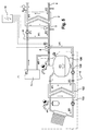
- the heating plant 1 can be used to heat the domestic hot water present in a secondary circuit 4 .
- This heating occurs by means of a heat exchanger 2 in which a primary circuit 3 of a first fluid transmits its heat to the domestic hot water.
- Said plant 1 comprises two heat energy production sources.
- a main source 5 may in particular be constituted by a boiler, but also by a connection to a centralized network heating the first fluid.
- Said network may thus be connected to a plurality of housing units or buildings, such as high-rise buildings used for residential purposes or for any other activity such as hospitals, canteens or offices.
- This plant 1 also comprises a secondary heat energy production source 6 .
- Said secondary source may, as shown, use solar energy from panels positioned on the roof of the building fitted with this plant.
- Said secondary source 6 may also be a heat pump and as a result use the heat supplied by the ground situated underneath the building fitted with a plant of this kind.
- This plant also comprises a three-port valve 7 arranged upstream of the secondary source 6 and downstream of the heat exchanger 2 .
- a by-pass pipe 8 is used to connect the three-port valve 7 hydraulically with the main source 5 and is therefore arranged in parallel relative to the secondary heat energy production source 6 .
- the three-port valve 7 is therefore a distribution valve but provision is also made for using a mixing valve positioned at a downstream junction between the secondary source 6 and the by-pass pipe 8 .
- the secondary heat energy production source 6 comprises a second heat exchanger 102 in which the first fluid of the primary circuit 3 harnesses the heat of a third fluid flowing inside a third circuit 103 .
- this third circuit 103 comprises a solar panel 104 in which the third fluid harnesses the solar energy, thereby generating an increase in its temperature.
- the secondary heat energy production source 6 comprises a closed storage tank 106 , thereby constituting an energy reserve for the first fluid flowing in the primary circuit 3 .
- a thermostat S2 is arranged in proximity to the upper end of the storage tank 106 for setting the temperature T2 of the first fluid at this level of the storage tank 106 .
- a thermostat S1 arranged in the three-port valve 7 allows the temperature T1 of the first fluid to be set at this level. So, when the temperature T2 of the first fluid is higher than the temperature T1 of the first fluid, a control unit 10 can be used to control the three-port valve 7 so that the flow of the first fluid is directed inside the secondary heat energy production source 6 .
- Figure 1 shows the plant at the start of a domestic hot water consumption peak.
- the domestic hot water of the secondary circuit 4 returns inside the heat exchanger 2 at a cold temperature.
- the temperature of the first fluid decreases inside the heat exchanger 2 , for example from 82°C to a value of 35°C.
- the first fluid then penetrates at a temperature of 35°C inside the storage tank 106 via another orifice situated at a lower end.
- the first fluid present inside the storage tank 106 may be at about 35°C at the bottom of the tank 106 and 95°C at the top of the tank. This temperature of 95°C is obtained by heating up the first fluid inside the second heat exchanger 102 by means of the third fluid flowing in the third circuit 103 .
- the water drawn from the storage tank 106 and which has its temperature measured by the thermostat S2 remains at 95°C.
- This first fluid at 95°C then supplies the main heat energy production source 5 which then has no need to heat up this first fluid and also supplies at output a first fluid at 95°C.
- a second three-port valve 9 can be used to mix the first fluid at 95°C with a portion of the first fluid at 35°C coming from the outlet of the first exchanger 2 .
- the first fluid loses no heat energy inside the first heat exchanger 2 .
- the first fluid may be directed towards the secondary heat energy production source 6 with a temperature higher than the first fluid contained in the bottom of the tank 106 .
- Said temperature may in particular be about 60°C thereby allowing a portion of the first lower temperature fluid contained in the bottom part of the storage tank 106 to be heated up.
- the storage tank 106 is then loaded with the first fluid at a high temperature which may in particular be 95°C.
- the control unit 10 controls the three-port valve 7 so as to direct the first fluid inside a by-pass pipe 8 .
- the first fluid allowing its heat to be exchanged with the domestic hot water in the first exchanger 2 , is no longer directed towards the secondary heat energy production source 6 .
- Such a step may in particular be obtained at the end of the domestic hot water consumption peak.
- the third circuit 103 can be used, inside the second exchanger 102 , to raise the temperature of the first fluid contained inside the storage tank 106 .
- This first fluid portion flows in a closed circuit between an intermediate orifice 107 and a lower orifice 108 of the storage tank 106 . The fluid then no longer escapes from the upper orifice 109 of the storage tank 106 .
- the control unit 10 prevents the first fluid of the primary circuit 3 from returning inside the secondary heat energy production source 6 .
- the first fluid portion contained inside the secondary heat energy production source 6 may be heated inside the second heat exchanger 102 . In this way, even when there is no significant need for domestic hot water consumption, the main heat energy production source 5 is not used so as to heat the first fluid contained inside the storage tank 106 of the secondary source 6 .
- the control unit 10 controls the three-port valve 7 in such a way as to direct the first fluid at the temperature T1 towards the secondary heat energy production source 6 .
- the heating plant uses the first fluid contained in the storage tank 106 at a temperature T2 above the temperature T1 at the outlet of the first heat exchanger 2 . As shown, the first fluid then penetrates into the lower orifice 108 of the storage tank 106 and causes the first fluid contained in the storage tank 106 to cool.
- the solar panel 104 is able to increase the temperature of the third fluid contained in the third circuit 103 , thereby increasing the temperature of the first fluid flowing inside the second exchanger 102 .
- the first fluid is able to penetrate both at the lower orifice 108 and the intermediate orifice 107 and allow the temperature T2 to remain above the temperature T1 even during periods of peak consumption of domestic hot water.
- the heating plant 11 may comprise a two-port valve 19 instead of the three-port valve previously used in figures 1 to 6 .
- the first fluid at the outlet of the main heat energy production source 5 is directly introduced inside the first exchanger 12 without being mixed with a first fluid portion emerging from the first heat exchanger 12 .
- the three-port valve 17 directs the first fluid inside the secondary heat energy production source 16 when the temperature T2 of the first fluid contained inside the storage tank 116 is above the temperature T1 of the fluid in the three-port valve 17 .
- the first fluid does not therefore flow in this case inside the by-pass pipe 18 .
- a heating plant may also be coupled with the heating network for heating the walls, floors or air in a building.
- the heating network 70 comprises an outlet 71 connected to the primary circuit 23 upstream of the three-port valve 27 and downstream of the first heat exchanger 22 .
- the heating network inlet 72 is, for its part, connected to the primary circuit 23 upstream of the first heat exchanger 22 and downstream of the main heat energy production source 25 .
- An arrangement of this kind thereby makes it possible to use the building's heating fluid which is in this case also the first fluid of the domestic hot water heating plant, and makes it possible to use the secondary heat energy production source 26 to heat up the first fluid which will then be transmitted in the inlet 72 of the heating network 70 .
- the heating network 70 may possibly not consume energy in such a way as to heat up the first fluid flowing in its pipes.
- the plant 21 comprises a three-port valve 29 for mixing the first fluid between the outlet of the main heat energy production source 25 and the first fluid emerging from the first heat exchanger 22 .
- Said three-port valve 29 then allows the temperature of the first fluid at the inlet of the first heat exchanger 22 to be lowered, thereby reducing the fouling thereof, by means of the lowest possible fluid temperature on the primary side of the exchanger.
- the heating plant 31 may also be connected to a heating network 80 and in this case, use a two-port valve 39 allowing the first fluid to flow inside the heat exchanger 32 without being mixed with a portion of the first fluid emerging from this exchanger.
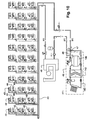
- a plant 41 may also comprise a plurality of first individual heat exchangers 42 to allow the domestic hot water to be heated.
- the plant may also comprise a plurality of heat exchangers 49 mounted in parallel relative to the first heat exchangers 42 and allowing the housing units to be heated.
- the different heat exchangers 42 , 49 are thus each arranged in an individual housing unit.
- the first fluid flowing in the primary circuit 43 penetrates inside a plurality of first exchangers 42 in order to transmit its heat energy to a plurality of secondary circuits 44 .
- Said heating plant 41 further always comprises a main heat energy production source 45 arranged hydraulically in series with a secondary heat energy production source 46 .
- the secondary source 46 is arranged upstream of the main source 45 .
- a heating plant 51 may also comprise an open storage tank 156 .
- the fluid flowing inside the tank 156 is different from the first fluid. It is a fourth fluid that flows in a fourth circuit 161 and transmits its heat energy to the first fluid inside a third heat exchanger 160 .
- Said type of storage tank 156 is particularly advantageous for ease of storage and transportation.
Landscapes
- Engineering & Computer Science (AREA)
- General Engineering & Computer Science (AREA)
- Mechanical Engineering (AREA)
- Combustion & Propulsion (AREA)
- Physics & Mathematics (AREA)
- Thermal Sciences (AREA)
- Chemical & Material Sciences (AREA)
- Sustainable Energy (AREA)
- Sustainable Development (AREA)
- Life Sciences & Earth Sciences (AREA)
- Water Supply & Treatment (AREA)
- Heat-Pump Type And Storage Water Heaters (AREA)
- Steam Or Hot-Water Central Heating Systems (AREA)
- Heat-Exchange Devices With Radiators And Conduit Assemblies (AREA)
- Instantaneous Water Boilers, Portable Hot-Water Supply Apparatuses, And Control Of Portable Hot-Water Supply Apparatuses (AREA)
Claims (9)
- Heizungsanlage (1, 11, 21, 31, 41, 51) zur Warmwassererzeugung in einem Haushalt, wobei die Anlage einen ersten Wärmetauscher (2, 12, 22, 32, 42, 52) umfasst, der an zwei Flüssigkeitskreisläufe angeschlossen ist, und in dem eine erste Flüssigkeit eines Primärkreislaufs (3, 13, 23, 33, 43, 53) Wärmeenergie an eine zweite Flüssigkeit eines Sekundärkreislaufs (4, 14, 24, 34, 44, 54) überträgt, der durch das Haushaltwarmwasser gebildet ist, dadurch gekennzeichnet, dass der Primärkreislauf (3, 13, 23, 33, 43, 53) umfasst:• eine Hauptwärmeenergieerzeugungsquelle (5, 15, 25, 35, 45, 55) und eine sekundäre Wärmeenergieerzeugungsquelle (6, 16, 26, 36, 46, 56), wobei die Hauptquelle und die sekundäre Quelle hydraulisch in Reihe geschaltet sind, wobei die sekundäre Quelle (6, 16, 26, 36, 46, 56) stromauf der Hauptquelle (5, 15, 25, 35, 45, 55) angeordnet ist;• ein Umgehungsrohr (8, 18, 28, 38, 48, 58) der sekundären Quelle, das in Bezug auf die sekundäre Quelle (6, 16, 26, 36, 46, 56) hydraulisch parallel angeordnet ist;• ein Dreiwegeventil (7, 17, 27, 37, 47, 57), das selektiv die erste Flüssigkeit in die sekundäre Quelle (6, 16, 26, 36, 46, 56) oder in das Umgehungsrohr (8, 18, 28, 38, 48, 58) leiten kann;und dass die Heizungsanlage (1, 11, 21, 31, 41, 51) eine Steuereinheit (10, 20, 30) zum Steuern des Dreiwegeventils (7, 17, 27, 37, 47, 57) umfasst.
- Anlage nach Anspruch 1, dadurch gekennzeichnet, dass das Dreiwegeventil (7, 17, 27, 37, 47, 57) die erste Flüssigkeit zur sekundären Wärmeenergieerzeugungsquelle (6, 16, 26, 36, 46) leitet, wenn die Temperatur T1 der ersten Flüssigkeit an einem vorgelagerten Übergang zwischen dem Umgehungsrohr (8, 18, 28, 38, 48, 58) und der sekundären Quelle (6, 16, 26, 36, 46) unter der Temperatur T2 der ersten Flüssigkeit im Inneren eines geschlossenen Speicherbehälters (106, 116, 126, 136, 146) der sekundären Quelle (6, 16, 26, 36, 46) liegt.
- Anlage nach Anspruch 2, dadurch gekennzeichnet, dass die sekundäre Wärmeenergieerzeugungsquelle (6, 16, 26, 36, 46) einen zweiten Wärmetauscher (102, 112, 122, 132, 142) umfasst, der an zwei Flüssigkeitskreisläufe angeschlossen ist, und in dem eine dritte Flüssigkeit eines dritten Kreislaufs (103, 113, 123, 133, 143) Wärmeenergie an die erste Flüssigkeit überträgt.
- Anlage nach Anspruch 1, dadurch gekennzeichnet, dass die sekundäre Wärmeenergieerzeugungsquelle (56) einen dritten Wärmetauscher (160) umfasst, der an die zwei Flüssigkeitskreisläufe angeschlossen ist, und in dem die erste Flüssigkeit des Primärkreislaufs (53) Wärmeenergie aus einer in einem vierten Kreislauf (161) fließenden vierten Flüssigkeit nutzt.
- Anlage nach Anspruch 4, dadurch gekennzeichnet, dass das Dreiwegeventil (57) die erste Flüssigkeit zur sekundären Wärmeenergieerzeugungsquelle (56) leitet, wenn die Temperatur T1 der ersten Flüssigkeit an einem vorgelagerten Übergang zwischen dem Umgehungsrohr (58) und der sekundären Quelle (56) unter der Temperatur T2 der vierten Flüssigkeit im Inneren eines offenen Speicherbehälters (156) der zweiten Quelle liegt.
- Anlage nach Anspruch 4, dadurch gekennzeichnet, dass die sekundäre Wärmeenergieerzeugungsquelle (56) einen zweiten Wärmetauscher (152) umfasst, der an zwei Flüssigkeitskreisläufe angeschlossen ist, und in dem eine dritte Flüssigkeit eines dritten Kreislaufs (153) Wärmeenergie an die vierte Flüssigkeit überträgt.
- Anlage nach einem der Ansprüche 3 oder 6, dadurch gekennzeichnet, dass der Speicherbehälter (106, 115, 126, 136, 146, 156) und der zweite Wärmtauscher (102, 112, 122, 132, 142, 152) hydraulisch parallel angeordnet sind.
- Anlage nach Anspruch 1, dadurch gekennzeichnet, dass der Primärkreislauf (23, 33) an ein Gebäudeheizungsnetz (70, 80) angeschlossen ist, wobei der Auslass (71, 81) des Netzes (70, 80) stromauf des Dreiwegeventils (27, 37) und stromab des ersten Wärmetauschers (22, 32) angeschlossen ist, wobei der Einlass (72, 82) des Netzes (70, 80) stromauf des ersten Wärmetauschers (22, 32) und stromab der Hauptwärmeenergieerzeugungsquelle (25, 35) angeschlossen ist.
- Anlage nach Anspruch 1, dadurch gekennzeichnet, dass sie eine Vielzahl von ersten, einzelnen Wärmetauschern (42) umfasst, von denen jeder jeweils in einer einzelnen Gehäuseeinheit angeordnet ist.
Priority Applications (5)
| Application Number | Priority Date | Filing Date | Title |
|---|---|---|---|
| EP10305468A EP2383523B1 (de) | 2010-04-30 | 2010-04-30 | Heizungsanlage zur Warmwasserproduktion in einem Haushalt |
| ES10305468T ES2394248T3 (es) | 2010-04-30 | 2010-04-30 | Planta de calentamiento para la producción de agua caliente doméstica |
| BR112012027632A BR112012027632A2 (pt) | 2010-04-30 | 2011-04-14 | usina de aquecimento |
| PCT/EP2011/055949 WO2011134803A1 (en) | 2010-04-30 | 2011-04-14 | Heating plant for the production of domestic hot water |
| RU2012151271/12A RU2508509C1 (ru) | 2010-04-30 | 2011-04-14 | Нагревательная установка для производства горячей воды для бытовых нужд |
Applications Claiming Priority (1)
| Application Number | Priority Date | Filing Date | Title |
|---|---|---|---|
| EP10305468A EP2383523B1 (de) | 2010-04-30 | 2010-04-30 | Heizungsanlage zur Warmwasserproduktion in einem Haushalt |
Publications (2)
| Publication Number | Publication Date |
|---|---|
| EP2383523A1 EP2383523A1 (de) | 2011-11-02 |
| EP2383523B1 true EP2383523B1 (de) | 2012-07-11 |
Family
ID=43033231
Family Applications (1)
| Application Number | Title | Priority Date | Filing Date |
|---|---|---|---|
| EP10305468A Not-in-force EP2383523B1 (de) | 2010-04-30 | 2010-04-30 | Heizungsanlage zur Warmwasserproduktion in einem Haushalt |
Country Status (5)
| Country | Link |
|---|---|
| EP (1) | EP2383523B1 (de) |
| BR (1) | BR112012027632A2 (de) |
| ES (1) | ES2394248T3 (de) |
| RU (1) | RU2508509C1 (de) |
| WO (1) | WO2011134803A1 (de) |
Families Citing this family (9)
| Publication number | Priority date | Publication date | Assignee | Title |
|---|---|---|---|---|
| KR101040693B1 (ko) * | 2011-03-10 | 2011-06-10 | 윤석구 | 에너지 절약형 중앙집중식 난방 및 급탕 시스템 |
| NL2009006C2 (nl) * | 2012-06-14 | 2013-12-17 | Samsom Installaties B V | Inrichting en werkwijze voor het verwarmen van een fluã¯dum, zoals water, verwarming en tapwater. |
| EP2685174B1 (de) * | 2012-07-11 | 2017-01-11 | Alfa Laval Corporate AB | Wärmeübertragungsmodul und dazugehöriges Verfahren |
| NL2016598B1 (nl) * | 2016-04-13 | 2017-11-07 | Rode Simon | Verwarmingsinrichting van een woning. |
| CN107504551A (zh) * | 2017-08-30 | 2017-12-22 | 宗永红 | 一种分体式电热取暖装置 |
| RU2674713C1 (ru) * | 2018-03-29 | 2018-12-12 | Публичное акционерное общество "Транснефть" (ПАО "Транснефть") | Система регулирования параметров теплоносителя на источнике теплоснабжения в зависимости от внутренней температуры воздуха у потребителей |
| NL2021476B1 (en) * | 2018-08-16 | 2020-02-24 | Inventum Beheer B V | Heating system |
| RO137916A3 (ro) * | 2023-09-06 | 2025-03-28 | Nicolae-Florin Zamfir | Sistem de încălzire a apei conţinând un acumulator termic nepresurizat, perete de clădire conţinând acumulatorul termic nepresurizat şi metoda de încălzire a apei utilizând sistemul de încălzire a apei menţionat |
| EP4703649A1 (de) * | 2024-09-03 | 2026-03-04 | Nicolae-Florin Zamfir | Druckloser thermischer speicher mit freon-spule und wand mit diesem thermischen speicher |
Family Cites Families (7)
| Publication number | Priority date | Publication date | Assignee | Title |
|---|---|---|---|---|
| US4191172A (en) * | 1978-05-19 | 1980-03-04 | General Motors Corporation | Thermostatic mixer valve |
| EP0006211B1 (de) * | 1978-06-16 | 1981-08-05 | Ciba-Geigy Ag | Vorrichtung zur Warmwasserbereitung mittels Sonnenenergie |
| ATA40493A (de) * | 1993-03-04 | 1997-08-15 | Vaillant Gmbh | Wasserheizer |
| DE19511369A1 (de) * | 1994-03-28 | 1995-10-05 | Vaillant Joh Gmbh & Co | Wasserheizanlage zur Bereitung von Brauch- und Heizwasser |
| AT403731B (de) * | 1994-08-03 | 1998-05-25 | Vaillant Gmbh | Wasserheizanlage |
| AT403842B (de) * | 1994-08-03 | 1998-05-25 | Vaillant Gmbh | Heizungsanlage mit zwei brauchwasserspeichern |
| EP2340403A1 (de) * | 2008-09-16 | 2011-07-06 | Asher Ben Shlomo | System zur bereitstellung einer solarheizfunktion für ein flüssigkeitserhitzungssystem |
-
2010
- 2010-04-30 EP EP10305468A patent/EP2383523B1/de not_active Not-in-force
- 2010-04-30 ES ES10305468T patent/ES2394248T3/es active Active
-
2011
- 2011-04-14 WO PCT/EP2011/055949 patent/WO2011134803A1/en not_active Ceased
- 2011-04-14 BR BR112012027632A patent/BR112012027632A2/pt not_active Application Discontinuation
- 2011-04-14 RU RU2012151271/12A patent/RU2508509C1/ru not_active IP Right Cessation
Also Published As
| Publication number | Publication date |
|---|---|
| BR112012027632A2 (pt) | 2016-08-09 |
| WO2011134803A1 (en) | 2011-11-03 |
| RU2508509C1 (ru) | 2014-02-27 |
| EP2383523A1 (de) | 2011-11-02 |
| ES2394248T3 (es) | 2013-01-30 |
Similar Documents
| Publication | Publication Date | Title |
|---|---|---|
| EP2383523A1 (de) | Heizungsanlage zur Warmwasserproduktion in einem Haushalt | |
| JP5553814B2 (ja) | 省エネ中央集中式暖房及び給湯システム | |
| EP2438358B1 (de) | Heizsystem | |
| CN103453566A (zh) | 串联式供暖及供热水系统 | |
| RU198390U1 (ru) | Комбинированное устройство нагрева технической воды и теплоносителя для отопления жилых помещений | |
| CN101936575A (zh) | 间接连接换热站系统 | |
| CN101761108A (zh) | 无负压生活冷热水混合给水系统 | |
| US20100326428A1 (en) | Method for heating fresh water for domestic or industrial use | |
| JP2012041757A (ja) | 再々交換省エネ建築システム | |
| KR20100031177A (ko) | 다기능 열교환기를 포함하는 난방 온수분배시스템 | |
| CZ2004135A3 (cs) | Způsob zásobování spotřebičů tepelnou energií, popř. chladicí energií a zařízení pro tento způsob | |
| US9835385B2 (en) | Three-conductor and four-conductor system for saving energy in connection with district heat | |
| KR102013197B1 (ko) | 공동주택 노후배관 철거 및 신설배관을 이용한 세대별 난방시스템 | |
| WO2009056816A1 (en) | Regenerative heating system | |
| KR101341631B1 (ko) | 열회수 급탕탱크 시스템 | |
| CN103994487A (zh) | 一种长输单管分布式混合供热系统 | |
| CZ2022400A3 (cs) | Způsob regulace teploty vody a topná soustava k jeho provádění | |
| EP2971981B1 (de) | Steuerungsverfahren für eine brauchwasserheizvorrichtung mit einem wärmespeicher | |
| CN207394942U (zh) | 一种高温水站供热系统 | |
| RU119858U1 (ru) | Система теплоснабжения здания | |
| RU94667U1 (ru) | Блочно-модульный индивидуальный тепловой пункт | |
| EP3611435A1 (de) | Heizsystem | |
| CN202092205U (zh) | 分体式楼宇混水供热装置 | |
| KR102584026B1 (ko) | 온수 분배기 결합 병렬형 급탕 가열 유닛 | |
| RU2647774C1 (ru) | Тепловой пункт с дополнительными помещениями |
Legal Events
| Date | Code | Title | Description |
|---|---|---|---|
| AK | Designated contracting states |
Kind code of ref document: A1 Designated state(s): AT BE BG CH CY CZ DE DK EE ES FI FR GB GR HR HU IE IS IT LI LT LU LV MC MK MT NL NO PL PT RO SE SI SK SM TR |
|
| AX | Request for extension of the european patent |
Extension state: AL BA ME RS |
|
| PUAI | Public reference made under article 153(3) epc to a published international application that has entered the european phase |
Free format text: ORIGINAL CODE: 0009012 |
|
| 17P | Request for examination filed |
Effective date: 20120117 |
|
| GRAP | Despatch of communication of intention to grant a patent |
Free format text: ORIGINAL CODE: EPIDOSNIGR1 |
|
| RIC1 | Information provided on ipc code assigned before grant |
Ipc: F24D 12/02 20060101ALI20120208BHEP Ipc: F24D 3/08 20060101AFI20120208BHEP Ipc: F24D 17/00 20060101ALI20120208BHEP Ipc: F24D 11/00 20060101ALI20120208BHEP |
|
| GRAS | Grant fee paid |
Free format text: ORIGINAL CODE: EPIDOSNIGR3 |
|
| GRAA | (expected) grant |
Free format text: ORIGINAL CODE: 0009210 |
|
| AK | Designated contracting states |
Kind code of ref document: B1 Designated state(s): AT BE BG CH CY CZ DE DK EE ES FI FR GB GR HR HU IE IS IT LI LT LU LV MC MK MT NL NO PL PT RO SE SI SK SM TR |
|
| REG | Reference to a national code |
Ref country code: GB Ref legal event code: FG4D |
|
| REG | Reference to a national code |
Ref country code: CH Ref legal event code: EP |
|
| REG | Reference to a national code |
Ref country code: AT Ref legal event code: REF Ref document number: 566339 Country of ref document: AT Kind code of ref document: T Effective date: 20120715 |
|
| REG | Reference to a national code |
Ref country code: IE Ref legal event code: FG4D |
|
| REG | Reference to a national code |
Ref country code: DE Ref legal event code: R096 Ref document number: 602010002188 Country of ref document: DE Effective date: 20120906 |
|
| REG | Reference to a national code |
Ref country code: NL Ref legal event code: T3 |
|
| REG | Reference to a national code |
Ref country code: LT Ref legal event code: MG4D Effective date: 20120711 |
|
| REG | Reference to a national code |
Ref country code: ES Ref legal event code: FG2A Ref document number: 2394248 Country of ref document: ES Kind code of ref document: T3 Effective date: 20130130 |
|
| PG25 | Lapsed in a contracting state [announced via postgrant information from national office to epo] |
Ref country code: LT Free format text: LAPSE BECAUSE OF FAILURE TO SUBMIT A TRANSLATION OF THE DESCRIPTION OR TO PAY THE FEE WITHIN THE PRESCRIBED TIME-LIMIT Effective date: 20120711 Ref country code: HR Free format text: LAPSE BECAUSE OF FAILURE TO SUBMIT A TRANSLATION OF THE DESCRIPTION OR TO PAY THE FEE WITHIN THE PRESCRIBED TIME-LIMIT Effective date: 20120711 Ref country code: IS Free format text: LAPSE BECAUSE OF FAILURE TO SUBMIT A TRANSLATION OF THE DESCRIPTION OR TO PAY THE FEE WITHIN THE PRESCRIBED TIME-LIMIT Effective date: 20121111 Ref country code: FI Free format text: LAPSE BECAUSE OF FAILURE TO SUBMIT A TRANSLATION OF THE DESCRIPTION OR TO PAY THE FEE WITHIN THE PRESCRIBED TIME-LIMIT Effective date: 20120711 Ref country code: NO Free format text: LAPSE BECAUSE OF FAILURE TO SUBMIT A TRANSLATION OF THE DESCRIPTION OR TO PAY THE FEE WITHIN THE PRESCRIBED TIME-LIMIT Effective date: 20121011 Ref country code: CY Free format text: LAPSE BECAUSE OF FAILURE TO SUBMIT A TRANSLATION OF THE DESCRIPTION OR TO PAY THE FEE WITHIN THE PRESCRIBED TIME-LIMIT Effective date: 20120711 |
|
| PG25 | Lapsed in a contracting state [announced via postgrant information from national office to epo] |
Ref country code: LV Free format text: LAPSE BECAUSE OF FAILURE TO SUBMIT A TRANSLATION OF THE DESCRIPTION OR TO PAY THE FEE WITHIN THE PRESCRIBED TIME-LIMIT Effective date: 20120711 Ref country code: SE Free format text: LAPSE BECAUSE OF FAILURE TO SUBMIT A TRANSLATION OF THE DESCRIPTION OR TO PAY THE FEE WITHIN THE PRESCRIBED TIME-LIMIT Effective date: 20120711 Ref country code: GR Free format text: LAPSE BECAUSE OF FAILURE TO SUBMIT A TRANSLATION OF THE DESCRIPTION OR TO PAY THE FEE WITHIN THE PRESCRIBED TIME-LIMIT Effective date: 20121012 Ref country code: SI Free format text: LAPSE BECAUSE OF FAILURE TO SUBMIT A TRANSLATION OF THE DESCRIPTION OR TO PAY THE FEE WITHIN THE PRESCRIBED TIME-LIMIT Effective date: 20120711 Ref country code: PL Free format text: LAPSE BECAUSE OF FAILURE TO SUBMIT A TRANSLATION OF THE DESCRIPTION OR TO PAY THE FEE WITHIN THE PRESCRIBED TIME-LIMIT Effective date: 20120711 Ref country code: PT Free format text: LAPSE BECAUSE OF FAILURE TO SUBMIT A TRANSLATION OF THE DESCRIPTION OR TO PAY THE FEE WITHIN THE PRESCRIBED TIME-LIMIT Effective date: 20121112 |
|
| PG25 | Lapsed in a contracting state [announced via postgrant information from national office to epo] |
Ref country code: DK Free format text: LAPSE BECAUSE OF FAILURE TO SUBMIT A TRANSLATION OF THE DESCRIPTION OR TO PAY THE FEE WITHIN THE PRESCRIBED TIME-LIMIT Effective date: 20120711 Ref country code: RO Free format text: LAPSE BECAUSE OF FAILURE TO SUBMIT A TRANSLATION OF THE DESCRIPTION OR TO PAY THE FEE WITHIN THE PRESCRIBED TIME-LIMIT Effective date: 20120711 Ref country code: EE Free format text: LAPSE BECAUSE OF FAILURE TO SUBMIT A TRANSLATION OF THE DESCRIPTION OR TO PAY THE FEE WITHIN THE PRESCRIBED TIME-LIMIT Effective date: 20120711 Ref country code: CZ Free format text: LAPSE BECAUSE OF FAILURE TO SUBMIT A TRANSLATION OF THE DESCRIPTION OR TO PAY THE FEE WITHIN THE PRESCRIBED TIME-LIMIT Effective date: 20120711 |
|
| PLBE | No opposition filed within time limit |
Free format text: ORIGINAL CODE: 0009261 |
|
| STAA | Information on the status of an ep patent application or granted ep patent |
Free format text: STATUS: NO OPPOSITION FILED WITHIN TIME LIMIT |
|
| PG25 | Lapsed in a contracting state [announced via postgrant information from national office to epo] |
Ref country code: SK Free format text: LAPSE BECAUSE OF FAILURE TO SUBMIT A TRANSLATION OF THE DESCRIPTION OR TO PAY THE FEE WITHIN THE PRESCRIBED TIME-LIMIT Effective date: 20120711 |
|
| 26N | No opposition filed |
Effective date: 20130412 |
|
| PG25 | Lapsed in a contracting state [announced via postgrant information from national office to epo] |
Ref country code: BG Free format text: LAPSE BECAUSE OF FAILURE TO SUBMIT A TRANSLATION OF THE DESCRIPTION OR TO PAY THE FEE WITHIN THE PRESCRIBED TIME-LIMIT Effective date: 20121011 |
|
| REG | Reference to a national code |
Ref country code: DE Ref legal event code: R097 Ref document number: 602010002188 Country of ref document: DE Effective date: 20130412 |
|
| PG25 | Lapsed in a contracting state [announced via postgrant information from national office to epo] |
Ref country code: MC Free format text: LAPSE BECAUSE OF FAILURE TO SUBMIT A TRANSLATION OF THE DESCRIPTION OR TO PAY THE FEE WITHIN THE PRESCRIBED TIME-LIMIT Effective date: 20120711 |
|
| REG | Reference to a national code |
Ref country code: IE Ref legal event code: MM4A |
|
| PG25 | Lapsed in a contracting state [announced via postgrant information from national office to epo] |
Ref country code: IE Free format text: LAPSE BECAUSE OF NON-PAYMENT OF DUE FEES Effective date: 20130430 |
|
| REG | Reference to a national code |
Ref country code: CH Ref legal event code: PL |
|
| PG25 | Lapsed in a contracting state [announced via postgrant information from national office to epo] |
Ref country code: CH Free format text: LAPSE BECAUSE OF NON-PAYMENT OF DUE FEES Effective date: 20140430 Ref country code: LI Free format text: LAPSE BECAUSE OF NON-PAYMENT OF DUE FEES Effective date: 20140430 |
|
| PG25 | Lapsed in a contracting state [announced via postgrant information from national office to epo] |
Ref country code: MT Free format text: LAPSE BECAUSE OF FAILURE TO SUBMIT A TRANSLATION OF THE DESCRIPTION OR TO PAY THE FEE WITHIN THE PRESCRIBED TIME-LIMIT Effective date: 20120711 |
|
| PG25 | Lapsed in a contracting state [announced via postgrant information from national office to epo] |
Ref country code: SM Free format text: LAPSE BECAUSE OF FAILURE TO SUBMIT A TRANSLATION OF THE DESCRIPTION OR TO PAY THE FEE WITHIN THE PRESCRIBED TIME-LIMIT Effective date: 20120711 |
|
| PG25 | Lapsed in a contracting state [announced via postgrant information from national office to epo] |
Ref country code: HU Free format text: LAPSE BECAUSE OF FAILURE TO SUBMIT A TRANSLATION OF THE DESCRIPTION OR TO PAY THE FEE WITHIN THE PRESCRIBED TIME-LIMIT; INVALID AB INITIO Effective date: 20100430 Ref country code: MK Free format text: LAPSE BECAUSE OF FAILURE TO SUBMIT A TRANSLATION OF THE DESCRIPTION OR TO PAY THE FEE WITHIN THE PRESCRIBED TIME-LIMIT Effective date: 20120711 Ref country code: LU Free format text: LAPSE BECAUSE OF NON-PAYMENT OF DUE FEES Effective date: 20130430 |
|
| REG | Reference to a national code |
Ref country code: FR Ref legal event code: PLFP Year of fee payment: 7 |
|
| REG | Reference to a national code |
Ref country code: FR Ref legal event code: PLFP Year of fee payment: 8 |
|
| REG | Reference to a national code |
Ref country code: FR Ref legal event code: PLFP Year of fee payment: 9 |
|
| REG | Reference to a national code |
Ref country code: DE Ref legal event code: R081 Ref document number: 602010002188 Country of ref document: DE Owner name: CETETHERM AB, SE Free format text: FORMER OWNER: ALFA LAVAL HES, LENTILLY, FR |
|
| REG | Reference to a national code |
Ref country code: DE Ref legal event code: R082 Ref document number: 602010002188 Country of ref document: DE Representative=s name: PATENTSHIP PATENTANWALTSGESELLSCHAFT MBH, DE |
|
| REG | Reference to a national code |
Ref country code: GB Ref legal event code: 732E Free format text: REGISTERED BETWEEN 20190214 AND 20190221 |
|
| REG | Reference to a national code |
Ref country code: NL Ref legal event code: HC Owner name: CETETHERM SAS; FR Free format text: DETAILS ASSIGNMENT: CHANGE OF OWNER(S), CHANGE OF OWNER(S) NAME; FORMER OWNER NAME: ALFA LAVAL HES Effective date: 20190923 Ref country code: NL Ref legal event code: PD Owner name: CETETHERM AB; SE Free format text: DETAILS ASSIGNMENT: CHANGE OF OWNER(S), ASSIGNMENT; FORMER OWNER NAME: CETETHERM SAS Effective date: 20190923 |
|
| REG | Reference to a national code |
Ref country code: AT Ref legal event code: PC Ref document number: 566339 Country of ref document: AT Kind code of ref document: T Owner name: CETETHERM AB, SE Effective date: 20191108 |
|
| REG | Reference to a national code |
Ref country code: BE Ref legal event code: HC Owner name: CETETHERM AB; SE Free format text: DETAILS ASSIGNMENT: CHANGE OF OWNER(S), CHANGEMENT DE NOM DU PROPRIETAIRE, CO-TITULAIRE; FORMER OWNER NAME: ALFA LAVAL HES Effective date: 20191028 Ref country code: BE Ref legal event code: PD Owner name: CETETHERM AB; SE Free format text: DETAILS ASSIGNMENT: CHANGE OF OWNER(S), AUTRE; FORMER OWNER NAME: CETETHERM AB Effective date: 20191028 |
|
| PGFP | Annual fee paid to national office [announced via postgrant information from national office to epo] |
Ref country code: TR Payment date: 20150430 Year of fee payment: 6 |
|
| PGFP | Annual fee paid to national office [announced via postgrant information from national office to epo] |
Ref country code: ES Payment date: 20200504 Year of fee payment: 11 |
|
| PGFP | Annual fee paid to national office [announced via postgrant information from national office to epo] |
Ref country code: IT Payment date: 20200409 Year of fee payment: 11 |
|
| PGFP | Annual fee paid to national office [announced via postgrant information from national office to epo] |
Ref country code: AT Payment date: 20210419 Year of fee payment: 12 |
|
| PG25 | Lapsed in a contracting state [announced via postgrant information from national office to epo] |
Ref country code: TR Free format text: LAPSE BECAUSE OF NON-PAYMENT OF DUE FEES Effective date: 20190430 |
|
| PGFP | Annual fee paid to national office [announced via postgrant information from national office to epo] |
Ref country code: NL Payment date: 20220412 Year of fee payment: 13 |
|
| REG | Reference to a national code |
Ref country code: ES Ref legal event code: FD2A Effective date: 20220728 |
|
| PGFP | Annual fee paid to national office [announced via postgrant information from national office to epo] |
Ref country code: GB Payment date: 20220412 Year of fee payment: 13 |
|
| PG25 | Lapsed in a contracting state [announced via postgrant information from national office to epo] |
Ref country code: ES Free format text: LAPSE BECAUSE OF NON-PAYMENT OF DUE FEES Effective date: 20210501 |
|
| REG | Reference to a national code |
Ref country code: AT Ref legal event code: MM01 Ref document number: 566339 Country of ref document: AT Kind code of ref document: T Effective date: 20220430 |
|
| PG25 | Lapsed in a contracting state [announced via postgrant information from national office to epo] |
Ref country code: AT Free format text: LAPSE BECAUSE OF NON-PAYMENT OF DUE FEES Effective date: 20220430 |
|
| PG25 | Lapsed in a contracting state [announced via postgrant information from national office to epo] |
Ref country code: IT Free format text: LAPSE BECAUSE OF NON-PAYMENT OF DUE FEES Effective date: 20200430 |
|
| PGFP | Annual fee paid to national office [announced via postgrant information from national office to epo] |
Ref country code: DE Payment date: 20230406 Year of fee payment: 14 |
|
| REG | Reference to a national code |
Ref country code: NL Ref legal event code: MM Effective date: 20230501 |
|
| GBPC | Gb: european patent ceased through non-payment of renewal fee |
Effective date: 20230430 |
|
| PG25 | Lapsed in a contracting state [announced via postgrant information from national office to epo] |
Ref country code: GB Free format text: LAPSE BECAUSE OF NON-PAYMENT OF DUE FEES Effective date: 20230430 |
|
| PG25 | Lapsed in a contracting state [announced via postgrant information from national office to epo] |
Ref country code: NL Free format text: LAPSE BECAUSE OF NON-PAYMENT OF DUE FEES Effective date: 20230501 Ref country code: GB Free format text: LAPSE BECAUSE OF NON-PAYMENT OF DUE FEES Effective date: 20230430 |
|
| PGFP | Annual fee paid to national office [announced via postgrant information from national office to epo] |
Ref country code: FR Payment date: 20240411 Year of fee payment: 15 |
|
| PGFP | Annual fee paid to national office [announced via postgrant information from national office to epo] |
Ref country code: BE Payment date: 20240410 Year of fee payment: 15 |
|
| REG | Reference to a national code |
Ref country code: DE Ref legal event code: R119 Ref document number: 602010002188 Country of ref document: DE |
|
| PG25 | Lapsed in a contracting state [announced via postgrant information from national office to epo] |
Ref country code: DE Free format text: LAPSE BECAUSE OF NON-PAYMENT OF DUE FEES Effective date: 20241105 |
|
| PG25 | Lapsed in a contracting state [announced via postgrant information from national office to epo] |
Ref country code: DE Free format text: LAPSE BECAUSE OF NON-PAYMENT OF DUE FEES Effective date: 20241105 |
|
| REG | Reference to a national code |
Ref country code: BE Ref legal event code: MM Effective date: 20250430 |
|
| PG25 | Lapsed in a contracting state [announced via postgrant information from national office to epo] |
Ref country code: FR Free format text: LAPSE BECAUSE OF NON-PAYMENT OF DUE FEES Effective date: 20250430 |
|
| PG25 | Lapsed in a contracting state [announced via postgrant information from national office to epo] |
Ref country code: BE Free format text: LAPSE BECAUSE OF NON-PAYMENT OF DUE FEES Effective date: 20250430 |