EP2383765A1 - Relais mit integrierter Sicherheitsbeschaltung - Google Patents
Relais mit integrierter Sicherheitsbeschaltung Download PDFInfo
- Publication number
- EP2383765A1 EP2383765A1 EP11002955A EP11002955A EP2383765A1 EP 2383765 A1 EP2383765 A1 EP 2383765A1 EP 11002955 A EP11002955 A EP 11002955A EP 11002955 A EP11002955 A EP 11002955A EP 2383765 A1 EP2383765 A1 EP 2383765A1
- Authority
- EP
- European Patent Office
- Prior art keywords
- relay
- coil
- control unit
- relay according
- board
- Prior art date
- Legal status (The legal status is an assumption and is not a legal conclusion. Google has not performed a legal analysis and makes no representation as to the accuracy of the status listed.)
- Granted
Links
Images

Classifications
-
- H—ELECTRICITY
- H01—ELECTRIC ELEMENTS
- H01H—ELECTRIC SWITCHES; RELAYS; SELECTORS; EMERGENCY PROTECTIVE DEVICES
- H01H50/00—Details of electromagnetic relays
- H01H50/02—Bases; Casings; Covers
-
- H—ELECTRICITY
- H01—ELECTRIC ELEMENTS
- H01H—ELECTRIC SWITCHES; RELAYS; SELECTORS; EMERGENCY PROTECTIVE DEVICES
- H01H47/00—Circuit arrangements not adapted to a particular application of the relay and designed to obtain desired operating characteristics or to provide energising current
- H01H47/22—Circuit arrangements not adapted to a particular application of the relay and designed to obtain desired operating characteristics or to provide energising current for supplying energising current for relay coil
Definitions
- the invention relates to a relay with a coil housing which comprises a coil arrangement and a movable armature, which permits or interrupts a current flow via two main contact terminals by the magnetic flux which can be generated in the coil arrangement by means of a coil current.
- Relays can be used in the form of monostable or bistable relays in a variety of applications such as the control of commercial vehicles, rail vehicles, construction equipment or industrial trucks.
- the relays had to be supplied externally, ie by the customer, with a precisely defined coil signal to control the relay. In the case of a too weak or too high coil signal it often came to faulty circuits of the relay.
- the invention is the object of the invention to provide a relay having a high switching safety.
- the now integrated in the relay control unit can be applied from the outside to the relay voltages even if they do not exactly match the voltage required to switch the relay, interpret as a control signal for the relay and output a well-defined coil current to the coil of the relay. Field failures caused by overcurrent coils can thus be avoided.
- control concepts with low power such as relay controls by on-board computer in vehicles can be realized. As a rule, these can not themselves provide correspondingly high pull-in or discharge currents for switching the relay.
- control unit may be formed on a substantially circular board. Since the coil assembly is formed generally round, the board with the control unit can be arranged to save space together with the coil assembly in the coil housing. Of course, the shape of the board can also be adapted to other geometric shapes of the coil arrangement, for example to a rectangular coil arrangement.
- the board of the control unit may have substantially the same diameter as the coil arrangement.
- the coil housing of the relay can be made compact in this way.
- a coil contact is preferably passed through the board.
- control electrodes for controlling the relay in a head portion of the relay and at the same time the control unit can be arranged with the board on the coil assembly.
- spring-loaded contact pins can be provided for contacting the control unit.
- the spring-loaded contact pins provide a reliable electrical connection, even when caused by a vehicle or a machine oscillations of the relay.
- the relay is preferably formed short-circuit proof.
- the relay and in particular the control unit of the relay are thus not damaged in the event of a short circuit.
- the relay has a polarity reversal protection. Damage caused by incorrect wiring of the relay can be avoided.
- the control unit of the relay can be designed such that a coil extinction by the control unit is vorappelbar. By the coil quenching, the control unit can put the relay in a defined switching state.
- the relay may have undervoltage protection.
- the undervoltage protection can protect the relay from indeterminate operating conditions and prevent the switching on of a consumption circuit by the relay if the supply voltage is too low.
- the relay integrated in the relay allows the relay to provide a high degree of electronic safety and enable almost powerless switching.
- the relay is designed as a bistable relay.
- At least one holding means in particular a permanent magnet, can be provided in the bistable relay with which the armature can be fixed in one position.
- the bistable relay can thereby be held without power in an on or off position even after switching off the control current.
- the relay may have a software-controlled switch-on and / or switch-off delay, if desired by the user.
- the relay can also be provided with overvoltage protection.
- Fig. 1 shows a relay 10 according to the invention, which comprises a connection unit 12 and a coil housing 14.
- the relay 10 is a bistable Relay.
- the connection unit 12 has two main contact terminals 16.1, 16.2. In Fig. 1 a first main contact terminal 16.1 is shown. A second main contact terminal 16.2 is a breakdown protection 18 in the illustration according to Fig. 1 covered.
- the connection unit 12 also has three control electrodes, of which in Fig. 1 two control electrodes 20.1, 20.2 are shown. A third control electrode is concealed in the rear part of the relay 10.
- the coil housing 14 comprises a coil arrangement 22, an armature 24 and a control unit 26.
- the control unit 26 is formed on a substantially round circuit board which has the same diameter as the coil arrangement 22 In this way, the control unit 26 can be integrated compactly into the coil housing 14 and is at the same time shielded against interference fields by the latter at the same time.
- a control signal in the form of a DC voltage is applied to the control electrodes 20.1, 20.2.
- the control signal is detected by the control unit 26, which is electrically connected by sprung contact pins 28.1, 28.2, 28.3 with the respective control electrodes 20.1, 20.2.
- the control unit 26 evaluates the control signal and energizes the coil arrangement 22.
- the magnetic flux induced in the coil arrangement 22 moves the armature 24.
- a main contact bridge 30 is arranged on the armature 24. By the main contact bridge 30, an electrical connection between the main contact terminals 16.1 and 16.2 according to the movement of the armature 24 is opened or closed.
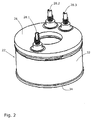
- Fig. 2 shows the coil assembly 22, the executed on a board control unit 26 and the spring-loaded pins 28.1, 28.2 and 28.3 of in Fig. 1 illustrated relays 10.
- the in Fig. 2 Relay elements shown are all arranged in the coil housing 14 of the relay 10.
- the coil assembly 22 includes a coil 32 and a bobbin 34.
- the control unit 26 is disposed directly on the bobbin 34.
- the spring-loaded contact pins 28.1, 28.2, 28.3 are electrically connected to the control electrodes.
- An electrical connection of the spring-loaded contact pins 28.1, 28.2, 28.3 is further formed by the control unit 26 through to the coil 32.
- the spring-loaded contact pin 28.3 is continuously applied with a positive voltage.
- the relay is then energized by applying a negative voltage to the spring-loaded contact pin 28.1 switched on and off by applying a negative voltage to the spring-loaded contact pin 28.2.
- control unit 26 After the relay has been switched on or off, the control unit 26 reduces the coil current, so that the control unit 26 allows a virtually powerless holding of the respective switching position of the relay 10.
- the control unit 26 is short-circuit proof and has a protected coil drive, a polarity reversal protection and a coil extinction.
- an undervoltage protection is integrated, which secures the relay from indeterminate operating conditions.
- control unit 26 can be controlled by control devices with low power, for example by on-board computer in vehicles.
- the arrangement of the control unit 26 in the coil housing 14 enables a compact design of the relay 10, so that the relay 10 according to the invention can replace a conventional relay of the same type.
- the relay can be designed with integrated control unit vapor jet.
Landscapes
- Physics & Mathematics (AREA)
- Electromagnetism (AREA)
- Relay Circuits (AREA)
- Electromagnets (AREA)
Abstract
Description
- Die Erfindung betrifft ein Relais mit einem Spulengehäuse, welches eine Spulenanordnung und einen beweglichen Anker umfasst, der durch den in der Spulenanordnung mittels eines Spulenstroms erzeugbaren magnetischen Fluss einen Stromfluss über zwei Hauptkontaktanschlüsse zulässt oder unterbricht.
- Relais können in Form von monostabilen oder bistabilen Relais in den unterschiedlichsten Einsatzbereichen wie beispielsweise zur Steuerung von Nutzfahrzeugen, Schienenfahrzeugen, Baumaschinen oder Flurfördermaschinen eingesetzt werden. Die Relais mussten hierzu bislang extern, das heißt kundenseitig, mit einem genau definierten Spulensignal zur Steuerung des Relais beaufschlagt werden. Im Falle eines zu schwachen oder zu hohen Spulensignals kam es dabei oft zu Fehlschaltungen des Relais.
- Der Erfindung liegt demgegenüber die Aufgabe zugrunde, ein Relais bereitzustellen, das eine hohe Schaltsicherheit aufweist.
- Diese Aufgabe wird erfindungsgemäß durch ein Relais der eingangs genannten Art gelöst, wobei im Spulengehäuse eine Steuereinheit zur Steuerung des Spulenstroms vorgesehen ist.
- Die nunmehr in das Relais integrierte Steuereinheit kann von außen an das Relais angelegte Spannungen auch, wenn diese der zur Schaltung des Relais erforderlichen Spannung nicht exakt entsprechen, als Steuersignal für das Relais interpretieren und einen genau definierten Spulenstrom an die Spule des Relais ausgeben. Feldausfälle durch mit Überstrom beaufschlagte Spulen können so vermieden werden. Darüber hinaus können mit dem erfindungsgemäßen Relais Ansteuerungskonzepte mit niedriger Leistung, beispielsweise Relaisansteuerungen durch Bordcomputer in Fahrzeugen, realisiert werden. Diese können in der Regel selbst keine entsprechend hohen Anzugs- oder Abwurfströme zur Schaltung des Relais zur Verfügung stellen.
- In einem bevorzugten Ausführungsbeispiel kann die Steuereinheit auf einer im Wesentlichen runden Platine ausgebildet sein. Da die Spulenanordnung in der Regel rund ausgebildet ist, kann die Platine mit der Steuereinheit Platz sparend zusammen mit der Spulenanordnung im Spulengehäuse angeordnet werden. Selbstverständlich kann die Form der Platine auch an andere geometrische Formen der Spulenanordnung, beispielsweise an eine rechteckige Spulenanordnung, angepasst sein.
- In einer besonders bevorzugten Ausführung der Erfindung kann die Platine der Steuereinheit im Wesentlichen den gleichen Durchmesser aufweisen wie die Spulenanordnung. Das Spulengehäuse des Relais kann auf diese Art und Weise kompakt ausgeführt werden.
- Eine Spulenkontaktierung ist vorzugsweise durch die Platine hindurchgeführt. In diesem Fall ergibt sich der Vorteil, dass Steuerelektroden zur Steuerung des Relais in einem Kopfteil des Relais und gleichzeitig die Steuereinheit mit der Platine auf der Spulenanordnung angeordnet werden können.
- In einer Weiterbildung der Erfindung können gefederte Kontaktstifte zur Kontaktierung der Steuereinheit vorgesehen sein. Die gefederten Kontaktstifte bieten auch bei durch ein Fahrzeug oder eine Maschine verursachten Schwingungen des Relais eine zuverlässige elektrische Verbindung.
- Das Relais ist vorzugsweise kurzschlusssicher ausgebildet. Das Relais und insbesondere die Steuereinheit des Relais werden damit auch im Falle eines Kurzschlusses nicht beschädigt.
- Weiterhin ist bevorzugt, dass das Relais einen Verpolschutz aufweist. Eine Beschädigung durch eine falsche Beschaltung des Relais kann hierdurch vermieden werden.
- Die Steuereinheit des Relais kann derart ausgebildet sein, dass eine Spulenlöschung durch die Steuereinheit vornehmbar ist. Durch die Spulenlöschung kann die Steuereinheit das Relais in einen definierten Schaltzustand versetzen.
- Das Relais kann einen Unterspannungsschutz aufweisen. Der Unterspannungsschutz kann das Relais vor unbestimmten Betriebszuständen sichern und das Einschalten eines Verbrauchsstromkreises durch das Relais bei zu geringer Versorgungsspannung verhindern.
- Durch die in das Relais integrierte Steuereinheit kann das Relais ein hohes Maß an elektronischer Sicherheit bieten sowie ein nahezu leistungsloses Schalten ermöglichen.
- In einer bevorzugten Ausführung der Erfindung ist das Relais als bistabiles Relais ausgeführt. In dem bistabilen Relais kann dabei mindestens ein Haltemittel, insbesondere ein Permanentmagnet, vorgesehen sein, mit dem der Anker in einer Position fixierbar ist. Das bistabile Relais kann dadurch auch nach Abschalten des Steuerstroms leistungslos in einer Ein-oder Aus-Position gehalten werden.
- Weiter kann das Relais eine softwaregesteuerte Einschalt- und/oder Ausschaltverzögerung aufweisen, sofern dies vom Anwender gewünscht wird. Das Relais kann zudem mit einem Überspannungsschutz versehen werden.
- Weitere Vorteile ergeben sich aus der Zeichnung, die ein erfindungsgemäßes Ausführungsbeispiel eines Relais mit integrierter Sicherheitsbeschaltung darstellt.
- Es zeigen:
- Fig. 1
- eine perspektivische, teilweise geschnittene Darstellung eines erfindungsgemäßen Relais; und
- Fig. 2
- eine perspektivische Darstellung der Spuleneinheit und Steuereinheit aus
Fig. 1 . -
Fig. 1 zeigt ein erfindungsgemäßes Relais 10, das eine Anschlusseinheit 12 und ein Spulengehäuse 14 umfasst. Das Relais 10 ist ein bistabiles Relais. Die Anschlusseinheit 12 weist zwei Hauptkontaktanschlüsse 16.1, 16.2 auf. InFig. 1 ist ein erster Hauptkontaktanschluss 16.1 dargestellt. Ein zweiter Hauptkontaktanschluss 16.2 wird von einem Durchschlagschutz 18 in der Darstellung gemäßFig. 1 verdeckt. Die Anschlusseinheit 12 weist weiterhin drei Steuerelektroden auf, von denen inFig. 1 zwei Steuerelektroden 20.1, 20.2 dargestellt sind. Eine dritte Steuerelektrode befindet sich verdeckt im hinteren Teil des Relais 10. Das Spulengehäuse 14 umfasst eine Spulenanordnung 22, einen Anker 24 sowie eine Steuereinheit 26. Die Steuereinheit 26 ist auf einer im Wesentlichen runden Platine ausgebildet, die den gleichen Durchmesser aufweist wie die Spulenanordnung 22. Die Steuereinheit 26 kann auf diese Art und Weise kompakt in das Spulengehäuse 14 integriert werden und wird durch dieses gleichzeitig gegen Störfelder nach außen abgeschirmt. - Zur Steuerung des Relais 10 wird an die Steuerelektroden 20.1, 20.2 ein Steuersignal in Form einer Gleichspannung angelegt. Das Steuersignal wird von der Steuereinheit 26 erfasst, die durch gefederte Kontaktstifte 28.1, 28.2, 28.3 elektrisch mit den jeweiligen Steuerelektroden 20.1, 20.2 verbunden ist. Die Steuereinheit 26 wertet das Steuersignal aus und bestromt die Spulenanordnung 22. Der in der Spulenanordnung 22 induzierte magnetische Fluss bewegt den Anker 24. Am Anker 24 ist eine Hauptkontaktbrücke 30 angeordnet. Durch die Hauptkontaktbrücke 30 wird eine elektrische Verbindung zwischen den Hauptkontaktanschlüssen 16.1 und 16.2 entsprechend der Bewegung des Ankers 24 geöffnet oder geschlossen.
-
Fig. 2 zeigt die Spulenanordnung 22, die auf einer Platine ausgeführte Steuereinheit 26 und die gefederten Kontaktstifte 28.1, 28.2 und 28.3 des inFig. 1 dargestellten Relais 10. Die inFig. 2 gezeigten Relaiselemente sind alle im Spulengehäuse 14 des Relais 10 angeordnet. Die Spulenanordnung 22 umfasst eine Spule 32 und einen Spulenkörper 34. Die Steuereinheit 26 ist unmittelbar auf dem Spulenkörper 34 angeordnet. Die gefederten Kontaktstifte 28.1, 28.2, 28.3 sind mit den Steuerelektroden elektrisch verbunden. Eine elektrische Verbindung der gefederten Kontaktstifte 28.1, 28.2, 28.3 ist weiterhin durch die Steuereinheit 26 hindurch zur Spule 32 ausgebildet. - Die Beschaltung der Steuereinheit 26 kann vorzugsweise auf drei Arten erfolgen:
- In einer ersten Variante sind zwei gefederte Kontaktstifte 28.2, 28.3 mit einer Versorgungsspannung beaufschlagt. Das Relais 10 wird durch einen High-Pegel am gefederten Kontaktstift 28.1 eingeschaltet und durch einen Low-Pegel am gefederten Kontaktstift 28.1 wieder ausgeschaltet. Der Bereich des High- und Low-Pegels kann dabei innerhalb der Betriebsspannung des Relais frei definiert werden.
- In einer zweiten Variante ist der gefederte Kontaktstift 28.1 elektrisch mit einer negativen Spannung beaufschlagt. Durch Anlegen einer positiven Spannung am gefederten Kontaktstift 28.2 wird das Relais ein- und durch Anlegen einer positiven Spannung am gefederten Kontaktstift 28.3 wieder ausgeschaltet.
- Schließlich wird in einer dritten Variante der gefederte Kontaktstift 28.3 kontinuierlich mit einer positiven Spannung beaufschlagt. Das Relais wird dann durch Anlegen einer negativen Spannung am gefederten Kontaktstift 28.1 ein- und durch Anlegen einer negativen Spannung am gefederten Kontaktstift 28.2 ausgeschaltet.
- Nachdem das Relais ein- oder ausgeschaltet wurde, reduziert die Steuereinheit 26 den Spulenstrom, sodass die Steuereinheit 26 ein nahezu leistungsloses Halten der jeweiligen Schaltposition des Relais 10 ermöglicht.
- Die Steuereinheit 26 ist kurzschlusssicher und weist eine geschützte Spulenansteuerung, einen Verpolschutz und eine Spulenlöschung auf. Darüber hinaus ist in die Steuereinheit 26 ein Unterspannungsschutz integriert, der das Relais vor unbestimmten Betriebszuständen sichert.
- Weiterhin kann die Steuereinheit 26 durch Ansteuergeräte mit niedriger Leistung, beispielsweise durch Bordcomputer in Fahrzeugen, angesteuert werden. Durch die Anordnung der Steuereinheit 26 im Spulengehäuse 14 wird eine kompakte Bauweise des Relais 10 ermöglicht, sodass das erfindungsgemäße Relais 10 ein herkömmliches Relais gleicher Bauart ersetzen kann. Darüber hinaus kann das Relais mit integrierter Steuereinheit dampfstrahldicht ausgeführt sein.
Claims (9)
- Relais (10) mit einem Spulengehäuse (14), welches eine Spulenanordnung (22) und einen beweglichen Anker (24) umfasst, der durch den in der Spulenanordnung (22) mittels eines Spulenstroms erzeugbaren magnetischen Fluss einen Stromfluss über zwei Hauptkontaktanschlüsse (16) zulässt oder unterbricht, dadurch gekennzeichnet, dass im Spulengehäuse (14) eine Steuereinheit (26) zur Steuerung des Spulenstroms vorgesehen ist.
- Relais nach Anspruch 1, dadurch gekennzeichnet, dass die Steuereinheit (26) auf einer im Wesentlichen runden Platine ausgebildet ist.
- Relais nach einem der vorhergehenden Ansprüche, dadurch gekennzeichnet, dass die Platine der Steuereinheit (26) im Wesentlichen denselben Durchmesser aufweist wie die Spulenanordnung (22).
- Relais nach einem der vorhergehenden Ansprüche, dadurch gekennzeichnet, dass eine Spulenkontaktierung durch die Platine hindurchgeführt ist.
- Relais nach einem der vorhergehenden Ansprüche, dadurch gekennzeichnet, dass gefederte Kontaktstifte (28.1, 28.2, 28.3) zur Kontaktierung der Steuereinheit vorgesehen sind.
- Relais nach einem der vorhergehenden Ansprüche, dadurch gekennzeichnet, dass das Relais (10) kurzschlusssicher ausgebildet ist.
- Relais nach einem der vorhergehenden Ansprüche, dadurch gekennzeichnet, dass das Relais (10) einen Verpolschutz aufweist.
- Relais nach einem der vorhergehenden Ansprüche, dadurch gekennzeichnet, dass durch die Steuereinheit (26) des Relais (10) eine Spulenlöschung vornehmbar ist.
- Relais nach einem der vorhergehenden Ansprüche, dadurch gekennzeichnet, dass das Relais (10) einen Unterspannungsschutz aufweist.
Applications Claiming Priority (1)
| Application Number | Priority Date | Filing Date | Title |
|---|---|---|---|
| DE102010018755A DE102010018755A1 (de) | 2010-04-29 | 2010-04-29 | Relais mit integrierter Sicherheitsbeschaltung |
Publications (2)
| Publication Number | Publication Date |
|---|---|
| EP2383765A1 true EP2383765A1 (de) | 2011-11-02 |
| EP2383765B1 EP2383765B1 (de) | 2020-01-15 |
Family
ID=44477671
Family Applications (1)
| Application Number | Title | Priority Date | Filing Date |
|---|---|---|---|
| EP11002955.0A Active EP2383765B1 (de) | 2010-04-29 | 2011-04-08 | Relais mit integrierter Sicherheitsbeschaltung |
Country Status (4)
| Country | Link |
|---|---|
| US (1) | US20110267158A1 (de) |
| EP (1) | EP2383765B1 (de) |
| CA (1) | CA2737696A1 (de) |
| DE (1) | DE102010018755A1 (de) |
Families Citing this family (3)
| Publication number | Priority date | Publication date | Assignee | Title |
|---|---|---|---|---|
| US20140133109A1 (en) * | 2012-10-19 | 2014-05-15 | Dynapar Corporation | Field replaceable auxiliary switch and control circuit assembly for an electrical contactor |
| DE102014007459A1 (de) | 2014-05-21 | 2015-11-26 | Ellenberger & Poensgen Gmbh | Leistungsrelais für ein Fahrzeug |
| DE202014010575U1 (de) | 2014-05-21 | 2016-01-07 | Ellenberger & Poensgen Gmbh | Leistungsrelais für ein Fahrzeug |
Citations (3)
| Publication number | Priority date | Publication date | Assignee | Title |
|---|---|---|---|---|
| EP1353348A1 (de) * | 2001-11-29 | 2003-10-15 | Matsushita Electric Works, Ltd. | Elektromagnetische schaltvorrichtung |
| US20040240140A1 (en) * | 2001-06-05 | 2004-12-02 | Trombetta, Llc | Integrated solenoid system |
| EP2019454A2 (de) * | 2007-07-27 | 2009-01-28 | Robert Bosch Gmbh | Stiftförmiges Kontaktelement und Steckverbindung |
Family Cites Families (40)
| Publication number | Priority date | Publication date | Assignee | Title |
|---|---|---|---|---|
| DE1105062B (de) | 1957-09-02 | 1961-04-20 | Keller Spezialtechnik G M B H | Elektronisches Relais |
| DE1514099A1 (de) | 1965-11-20 | 1969-10-02 | Kieninger & Obergfell | Relais oder Kleinschuetz zur Verwendung auf Leiterplatten,insbesondere gedruckte Schaltungen |
| CH486769A (de) | 1969-05-21 | 1970-02-28 | Landis & Gyr Ag | Thermisches Relais |
| DE2405383A1 (de) | 1974-02-05 | 1975-08-07 | Bosch Gmbh Robert | Spulentragkoerper fuer relais |
| SE384611B (sv) | 1974-06-20 | 1976-05-10 | Asea Ab | Filtreringsanordning vid releskydd |
| DE2954352C2 (de) * | 1979-03-30 | 1984-12-13 | Hans 8024 Deisenhofen Sauer | Gepoltes Zungenkontaktrelais |
| DE3047488A1 (de) | 1980-12-17 | 1982-07-22 | Brown, Boveri & Cie Ag, 6800 Mannheim | Elektronische schaltungsanordnung fuer ein elektromagnetisches schaltgeraet |
| FR2520152B1 (fr) * | 1982-01-20 | 1986-02-28 | Telemecanique Electrique | Electro-aimant a equipage mobile a aimant permanent a fonctionnement monostable |
| DE3306019C2 (de) | 1983-02-22 | 1984-12-13 | Stribel GmbH, 7443 Frickenhausen | Elektromagnetisches Relais |
| FR2562322B1 (fr) * | 1984-03-30 | 1986-08-08 | Ecans | Interrupteur electromagnetique de batterie a commande electronique |
| US4603366A (en) * | 1984-07-12 | 1986-07-29 | Siemens Corporate Research & Support, Inc. | High-speed voltage-sensitive circuit breaker |
| CH672039A5 (de) | 1986-10-31 | 1989-10-13 | Sprecher & Schuh Ag | |
| DE8709893U1 (de) | 1987-07-18 | 1987-09-10 | Eichhoff-Werke GmbH, 5880 Lüdenscheid | Elektromagnetisches Relais |
| EP0392058A1 (de) | 1989-04-13 | 1990-10-17 | Siemens Aktiengesellschaft | Schaltungsanordnung zur Ansteuerung mindestens eines elektromagnetishen Relais |
| US5914849A (en) | 1994-04-26 | 1999-06-22 | Kilovac Corporation | DC actuator control circuit with voltage compensation, current control and fast dropout period |
| DE4415929A1 (de) | 1994-05-05 | 1995-11-09 | Siemens Ag | Modulrelais |
| US5541800A (en) * | 1995-03-22 | 1996-07-30 | Hubbell Incorporated | Reverse wiring indicator for GFCI receptacles |
| FR2736100B1 (fr) | 1995-06-27 | 1997-08-01 | Valeo Equip Electr Moteur | Contacteur de demarreur comportant un circuit electronique de commande integre au contacteur, et demarreur de vehicule comportant un tel contacteur |
| DE19524003A1 (de) | 1995-06-30 | 1997-01-09 | Siemens Ag | Elektronische Schaltungsanordnung zur Relaisansteuerung |
| SE505747C2 (sv) | 1996-02-07 | 1997-10-06 | Asea Brown Boveri | Kontaktorutrustning |
| FR2753302B1 (fr) * | 1996-09-06 | 1998-10-16 | Valeo Equip Electr Moteur | Contacteur de demarreur comportant un circuit electronique de commande integre au contacteur, et demarreur de vehicule comportant un tel contacteur |
| FR2755535B1 (fr) | 1996-11-07 | 1998-12-04 | Valeo Equip Electr Moteur | Contacteur de demarreur comportant un circuit electronique de commande integre au contacteur, et demarreur de vehicule comportant un tel contacteur |
| FR2759810B1 (fr) * | 1997-02-14 | 1999-04-09 | Valeo Equip Electr Moteur | Contacteur pour un demarreur de vehicule automobile comportant des moyens perfectionnes de protection d'un circuit electronique |
| DE19738989A1 (de) | 1997-09-05 | 1999-03-18 | Siemens Ag | Elektronisch gesteuertes Relais |
| DE19744396A1 (de) * | 1997-10-08 | 1999-04-15 | Heinrich Kissling Gmbh & Co Kg | Bistabiles Relais, insbesondere für den Hochstrombereich |
| DE19753852A1 (de) | 1997-12-04 | 1999-06-17 | Siemens Ag | Elektromagnetisches Relais |
| DE19939650C2 (de) | 1999-08-13 | 2001-08-02 | Siemens Ag | Schaltungsanordnung zum Betrieb eines Relais |
| DE10105205A1 (de) | 2001-01-30 | 2002-08-14 | Maerklin & Cie Gmbh Geb | Steuereinheit für ein Arbeitsorgan einer Modellbahn |
| DE10155969A1 (de) | 2001-11-14 | 2003-05-22 | Bosch Gmbh Robert | Vorrichtung zur Ansteuerung eines elektromagnetischen Stellgliedes |
| CN1220236C (zh) * | 2002-10-09 | 2005-09-21 | 浙江东正电气有限公司 | 具有反接线保护功能的接地故障断路器 |
| JP4413724B2 (ja) | 2003-12-11 | 2010-02-10 | アンデン株式会社 | リレー装置 |
| DE10358858A1 (de) | 2003-12-16 | 2005-07-14 | Robert Bosch Gmbh | Verfahren und Vorrichtung zum Betreiben einer induktiven Last mit unterschiedlichen elektrischen Spannungen |
| JP4306604B2 (ja) * | 2004-12-20 | 2009-08-05 | 株式会社デンソー | スタータ用マグネットスイッチ |
| US7212090B2 (en) * | 2004-12-22 | 2007-05-01 | International Controls And Measurements Corporation | Relay with core conductor and current sensing |
| KR100802910B1 (ko) | 2007-03-05 | 2008-02-13 | 엘에스산전 주식회사 | 전자접촉기의 코일 구동장치 |
| CN102820167A (zh) * | 2007-03-27 | 2012-12-12 | 施耐德电器工业公司 | 双稳态电磁促动器 |
| DE102007031995A1 (de) | 2007-07-09 | 2009-01-15 | Moeller Gmbh | Steuervorrichtung für ein Schaltgerät mit Anzugs- und/oder Haltespule sowie Verfahren zum Steuern des durch die Spule fließenden Stroms |
| DE102007046634B3 (de) | 2007-09-27 | 2009-05-28 | Moeller Gmbh | Spannungsversorgung für ein spannungs- oder stromauslösendes Schaltgerät sowie deren Verwendung in einem solchen Schaltgerät und Verfahren zur Spannungsversorgung für ein solches Schaltgerät |
| US7868720B2 (en) * | 2007-11-01 | 2011-01-11 | Tyco Electronics Corporation India | Hermetically sealed relay |
| JP5195144B2 (ja) | 2008-08-07 | 2013-05-08 | 株式会社デンソー | 電磁スイッチ |
-
2010
- 2010-04-29 DE DE102010018755A patent/DE102010018755A1/de active Pending
-
2011
- 2011-04-08 EP EP11002955.0A patent/EP2383765B1/de active Active
- 2011-04-18 CA CA2737696A patent/CA2737696A1/en not_active Abandoned
- 2011-04-25 US US13/093,257 patent/US20110267158A1/en not_active Abandoned
Patent Citations (3)
| Publication number | Priority date | Publication date | Assignee | Title |
|---|---|---|---|---|
| US20040240140A1 (en) * | 2001-06-05 | 2004-12-02 | Trombetta, Llc | Integrated solenoid system |
| EP1353348A1 (de) * | 2001-11-29 | 2003-10-15 | Matsushita Electric Works, Ltd. | Elektromagnetische schaltvorrichtung |
| EP2019454A2 (de) * | 2007-07-27 | 2009-01-28 | Robert Bosch Gmbh | Stiftförmiges Kontaktelement und Steckverbindung |
Also Published As
| Publication number | Publication date |
|---|---|
| US20110267158A1 (en) | 2011-11-03 |
| EP2383765B1 (de) | 2020-01-15 |
| CA2737696A1 (en) | 2011-10-29 |
| DE102010018755A1 (de) | 2011-11-03 |
Similar Documents
| Publication | Publication Date | Title |
|---|---|---|
| DE102010032456A1 (de) | Elektrisches Schaltschütz | |
| EP2532088A2 (de) | Schaltungsanordnung zur überspannungsbegrenzung einer erregerwicklung einer synchronmaschine mit schnellentregung | |
| EP2383764A1 (de) | Bistabiles Relais | |
| EP2795652A1 (de) | Vorrichtung und verfahren zum schalten elektrischer lastkreise | |
| EP2507885A1 (de) | Bauelement zur begrenzung von strömen in elektrischen schaltungen | |
| DE102015224658A1 (de) | Elektromechanischer Schutzschalter | |
| DE102007041972B3 (de) | Vorrichtung zur Steuerung eines motorisch angetriebenen Schalterantriebs für ein Schaltgerät mit intergrierter Steuereinheit | |
| EP2383765A1 (de) | Relais mit integrierter Sicherheitsbeschaltung | |
| EP0987418B1 (de) | System zum Glühen und Ionenstrom-Messen und Ionenstrom-Glühkerzen für dieses System | |
| DE2400396B2 (de) | Schaltvorrichtung zum schutze eines von akkumulatoren gespeisten gleichstromkreises - insbesondere fuer ein kraftfahrzeug mit elektroantrieb | |
| EP1780742A1 (de) | Schaltgerät mit einer Schaltvorrichtung und einem elektronischen Bauelement sowie elektrische Zusatzschaltung dafür | |
| DE2508299A1 (de) | Elektrisches schaltgeraet | |
| EP1072790B1 (de) | Ionenstrommessglühkerze und Verfahren und Schaltung zu ihrer Ansteuerung | |
| DE3005460C2 (de) | Elektromagnetischer Schalter | |
| DE102013111954B4 (de) | Aufsteckbares Modul für ein Schütz sowie ein Schütz mit einem derartigen Modul | |
| EP3433871B1 (de) | Vorrichtung zur messung eines zustands eines elektrischen schalters, elektrischer schalter und verfahren zur messung eines zustands eines elektrischen schalters | |
| EP3655784A1 (de) | Stromsensoranordnung | |
| DE112012001231B4 (de) | Startstrombegrenzungsvorrichtung | |
| EP2064721B1 (de) | Schaltgerät mit integriertem hauptstrombahn-abgriff | |
| DE102024106555B3 (de) | Schaltvorrichtung und Betriebsvorrichtung mit einer Schaltvorrichtung | |
| DE4244118C1 (de) | Vorrichtung zum Schützen von Relaiskontakten gegen Überlastung | |
| DE102015202221A1 (de) | Automatische Kurzschlusstrennvorrichtung | |
| WO2018099961A1 (de) | Vorrichtung zum trennen eines bordnetzes von einer energiequelle | |
| EP0949737A2 (de) | Verpolschutzschaltung | |
| DE112013005173B4 (de) | Ansteuerschaltung für den elektromagnetischen Antrieb eines Schaltgeräts, insbesondere eines Schützes |
Legal Events
| Date | Code | Title | Description |
|---|---|---|---|
| AK | Designated contracting states |
Kind code of ref document: A1 Designated state(s): AL AT BE BG CH CY CZ DE DK EE ES FI FR GB GR HR HU IE IS IT LI LT LU LV MC MK MT NL NO PL PT RO RS SE SI SK SM TR |
|
| AX | Request for extension of the european patent |
Extension state: BA ME |
|
| PUAI | Public reference made under article 153(3) epc to a published international application that has entered the european phase |
Free format text: ORIGINAL CODE: 0009012 |
|
| 17P | Request for examination filed |
Effective date: 20120413 |
|
| 17Q | First examination report despatched |
Effective date: 20160114 |
|
| STAA | Information on the status of an ep patent application or granted ep patent |
Free format text: STATUS: EXAMINATION IS IN PROGRESS |
|
| GRAP | Despatch of communication of intention to grant a patent |
Free format text: ORIGINAL CODE: EPIDOSNIGR1 |
|
| STAA | Information on the status of an ep patent application or granted ep patent |
Free format text: STATUS: GRANT OF PATENT IS INTENDED |
|
| INTG | Intention to grant announced |
Effective date: 20191015 |
|
| GRAS | Grant fee paid |
Free format text: ORIGINAL CODE: EPIDOSNIGR3 |
|
| GRAA | (expected) grant |
Free format text: ORIGINAL CODE: 0009210 |
|
| STAA | Information on the status of an ep patent application or granted ep patent |
Free format text: STATUS: THE PATENT HAS BEEN GRANTED |
|
| AK | Designated contracting states |
Kind code of ref document: B1 Designated state(s): AL AT BE BG CH CY CZ DE DK EE ES FI FR GB GR HR HU IE IS IT LI LT LU LV MC MK MT NL NO PL PT RO RS SE SI SK SM TR |
|
| REG | Reference to a national code |
Ref country code: GB Ref legal event code: FG4D Free format text: NOT ENGLISH Ref country code: CH Ref legal event code: EP |
|
| REG | Reference to a national code |
Ref country code: IE Ref legal event code: FG4D Free format text: LANGUAGE OF EP DOCUMENT: GERMAN |
|
| REG | Reference to a national code |
Ref country code: DE Ref legal event code: R096 Ref document number: 502011016397 Country of ref document: DE |
|
| REG | Reference to a national code |
Ref country code: AT Ref legal event code: REF Ref document number: 1225883 Country of ref document: AT Kind code of ref document: T Effective date: 20200215 |
|
| REG | Reference to a national code |
Ref country code: NL Ref legal event code: FP |
|
| REG | Reference to a national code |
Ref country code: DE Ref legal event code: R082 Ref document number: 502011016397 Country of ref document: DE Representative=s name: MURGITROYD & COMPANY, DE Ref country code: DE Ref legal event code: R081 Ref document number: 502011016397 Country of ref document: DE Owner name: TE CONNECTIVITY KISSLING PRODUCTS GMBH, DE Free format text: FORMER OWNER: KISSLING ELEKTROTECHNIK GMBH, 72218 WILDBERG, DE |
|
| REG | Reference to a national code |
Ref country code: SE Ref legal event code: TRGR |
|
| REG | Reference to a national code |
Ref country code: NL Ref legal event code: HC Owner name: TE CONNECTIVITY KISSLING PRODUCTS GMBH; DE Free format text: DETAILS ASSIGNMENT: CHANGE OF OWNER(S), CHANGE OF OWNER(S) NAME; FORMER OWNER NAME: KISSLING ELEKTROTECHNIK GMBH Effective date: 20200605 |
|
| REG | Reference to a national code |
Ref country code: LT Ref legal event code: MG4D |
|
| PG25 | Lapsed in a contracting state [announced via postgrant information from national office to epo] |
Ref country code: NO Free format text: LAPSE BECAUSE OF FAILURE TO SUBMIT A TRANSLATION OF THE DESCRIPTION OR TO PAY THE FEE WITHIN THE PRESCRIBED TIME-LIMIT Effective date: 20200415 Ref country code: FI Free format text: LAPSE BECAUSE OF FAILURE TO SUBMIT A TRANSLATION OF THE DESCRIPTION OR TO PAY THE FEE WITHIN THE PRESCRIBED TIME-LIMIT Effective date: 20200115 Ref country code: RS Free format text: LAPSE BECAUSE OF FAILURE TO SUBMIT A TRANSLATION OF THE DESCRIPTION OR TO PAY THE FEE WITHIN THE PRESCRIBED TIME-LIMIT Effective date: 20200115 Ref country code: PT Free format text: LAPSE BECAUSE OF FAILURE TO SUBMIT A TRANSLATION OF THE DESCRIPTION OR TO PAY THE FEE WITHIN THE PRESCRIBED TIME-LIMIT Effective date: 20200607 |
|
| PG25 | Lapsed in a contracting state [announced via postgrant information from national office to epo] |
Ref country code: GR Free format text: LAPSE BECAUSE OF FAILURE TO SUBMIT A TRANSLATION OF THE DESCRIPTION OR TO PAY THE FEE WITHIN THE PRESCRIBED TIME-LIMIT Effective date: 20200416 Ref country code: HR Free format text: LAPSE BECAUSE OF FAILURE TO SUBMIT A TRANSLATION OF THE DESCRIPTION OR TO PAY THE FEE WITHIN THE PRESCRIBED TIME-LIMIT Effective date: 20200115 Ref country code: LV Free format text: LAPSE BECAUSE OF FAILURE TO SUBMIT A TRANSLATION OF THE DESCRIPTION OR TO PAY THE FEE WITHIN THE PRESCRIBED TIME-LIMIT Effective date: 20200115 Ref country code: BG Free format text: LAPSE BECAUSE OF FAILURE TO SUBMIT A TRANSLATION OF THE DESCRIPTION OR TO PAY THE FEE WITHIN THE PRESCRIBED TIME-LIMIT Effective date: 20200415 Ref country code: IS Free format text: LAPSE BECAUSE OF FAILURE TO SUBMIT A TRANSLATION OF THE DESCRIPTION OR TO PAY THE FEE WITHIN THE PRESCRIBED TIME-LIMIT Effective date: 20200515 |
|
| REG | Reference to a national code |
Ref country code: DE Ref legal event code: R026 Ref document number: 502011016397 Country of ref document: DE |
|
| PLBI | Opposition filed |
Free format text: ORIGINAL CODE: 0009260 |
|
| PLAX | Notice of opposition and request to file observation + time limit sent |
Free format text: ORIGINAL CODE: EPIDOSNOBS2 |
|
| PG25 | Lapsed in a contracting state [announced via postgrant information from national office to epo] |
Ref country code: LT Free format text: LAPSE BECAUSE OF FAILURE TO SUBMIT A TRANSLATION OF THE DESCRIPTION OR TO PAY THE FEE WITHIN THE PRESCRIBED TIME-LIMIT Effective date: 20200115 Ref country code: ES Free format text: LAPSE BECAUSE OF FAILURE TO SUBMIT A TRANSLATION OF THE DESCRIPTION OR TO PAY THE FEE WITHIN THE PRESCRIBED TIME-LIMIT Effective date: 20200115 Ref country code: SK Free format text: LAPSE BECAUSE OF FAILURE TO SUBMIT A TRANSLATION OF THE DESCRIPTION OR TO PAY THE FEE WITHIN THE PRESCRIBED TIME-LIMIT Effective date: 20200115 Ref country code: CZ Free format text: LAPSE BECAUSE OF FAILURE TO SUBMIT A TRANSLATION OF THE DESCRIPTION OR TO PAY THE FEE WITHIN THE PRESCRIBED TIME-LIMIT Effective date: 20200115 Ref country code: RO Free format text: LAPSE BECAUSE OF FAILURE TO SUBMIT A TRANSLATION OF THE DESCRIPTION OR TO PAY THE FEE WITHIN THE PRESCRIBED TIME-LIMIT Effective date: 20200115 Ref country code: DK Free format text: LAPSE BECAUSE OF FAILURE TO SUBMIT A TRANSLATION OF THE DESCRIPTION OR TO PAY THE FEE WITHIN THE PRESCRIBED TIME-LIMIT Effective date: 20200115 Ref country code: SM Free format text: LAPSE BECAUSE OF FAILURE TO SUBMIT A TRANSLATION OF THE DESCRIPTION OR TO PAY THE FEE WITHIN THE PRESCRIBED TIME-LIMIT Effective date: 20200115 Ref country code: EE Free format text: LAPSE BECAUSE OF FAILURE TO SUBMIT A TRANSLATION OF THE DESCRIPTION OR TO PAY THE FEE WITHIN THE PRESCRIBED TIME-LIMIT Effective date: 20200115 |
|
| 26 | Opposition filed |
Opponent name: LAYHER AG Effective date: 20201007 Opponent name: E-T-A ELEKTROTECHNISCHE APPARATE GMBH Effective date: 20201006 |
|
| PG25 | Lapsed in a contracting state [announced via postgrant information from national office to epo] |
Ref country code: MC Free format text: LAPSE BECAUSE OF FAILURE TO SUBMIT A TRANSLATION OF THE DESCRIPTION OR TO PAY THE FEE WITHIN THE PRESCRIBED TIME-LIMIT Effective date: 20200115 |
|
| REG | Reference to a national code |
Ref country code: CH Ref legal event code: PL |
|
| PLBB | Reply of patent proprietor to notice(s) of opposition received |
Free format text: ORIGINAL CODE: EPIDOSNOBS3 |
|
| PG25 | Lapsed in a contracting state [announced via postgrant information from national office to epo] |
Ref country code: CH Free format text: LAPSE BECAUSE OF NON-PAYMENT OF DUE FEES Effective date: 20200430 Ref country code: LU Free format text: LAPSE BECAUSE OF NON-PAYMENT OF DUE FEES Effective date: 20200408 Ref country code: LI Free format text: LAPSE BECAUSE OF NON-PAYMENT OF DUE FEES Effective date: 20200430 |
|
| REG | Reference to a national code |
Ref country code: BE Ref legal event code: MM Effective date: 20200430 |
|
| PG25 | Lapsed in a contracting state [announced via postgrant information from national office to epo] |
Ref country code: BE Free format text: LAPSE BECAUSE OF NON-PAYMENT OF DUE FEES Effective date: 20200430 Ref country code: PL Free format text: LAPSE BECAUSE OF FAILURE TO SUBMIT A TRANSLATION OF THE DESCRIPTION OR TO PAY THE FEE WITHIN THE PRESCRIBED TIME-LIMIT Effective date: 20200115 Ref country code: SI Free format text: LAPSE BECAUSE OF FAILURE TO SUBMIT A TRANSLATION OF THE DESCRIPTION OR TO PAY THE FEE WITHIN THE PRESCRIBED TIME-LIMIT Effective date: 20200115 |
|
| PG25 | Lapsed in a contracting state [announced via postgrant information from national office to epo] |
Ref country code: IE Free format text: LAPSE BECAUSE OF NON-PAYMENT OF DUE FEES Effective date: 20200408 |
|
| REG | Reference to a national code |
Ref country code: AT Ref legal event code: MM01 Ref document number: 1225883 Country of ref document: AT Kind code of ref document: T Effective date: 20200408 |
|
| RAP4 | Party data changed (patent owner data changed or rights of a patent transferred) |
Owner name: TE CONNECTIVITY KISSLING PRODUCTS GMBH |
|
| PG25 | Lapsed in a contracting state [announced via postgrant information from national office to epo] |
Ref country code: AT Free format text: LAPSE BECAUSE OF NON-PAYMENT OF DUE FEES Effective date: 20200408 |
|
| PG25 | Lapsed in a contracting state [announced via postgrant information from national office to epo] |
Ref country code: TR Free format text: LAPSE BECAUSE OF FAILURE TO SUBMIT A TRANSLATION OF THE DESCRIPTION OR TO PAY THE FEE WITHIN THE PRESCRIBED TIME-LIMIT Effective date: 20200115 Ref country code: MT Free format text: LAPSE BECAUSE OF FAILURE TO SUBMIT A TRANSLATION OF THE DESCRIPTION OR TO PAY THE FEE WITHIN THE PRESCRIBED TIME-LIMIT Effective date: 20200115 Ref country code: CY Free format text: LAPSE BECAUSE OF FAILURE TO SUBMIT A TRANSLATION OF THE DESCRIPTION OR TO PAY THE FEE WITHIN THE PRESCRIBED TIME-LIMIT Effective date: 20200115 |
|
| PG25 | Lapsed in a contracting state [announced via postgrant information from national office to epo] |
Ref country code: MK Free format text: LAPSE BECAUSE OF FAILURE TO SUBMIT A TRANSLATION OF THE DESCRIPTION OR TO PAY THE FEE WITHIN THE PRESCRIBED TIME-LIMIT Effective date: 20200115 Ref country code: AL Free format text: LAPSE BECAUSE OF FAILURE TO SUBMIT A TRANSLATION OF THE DESCRIPTION OR TO PAY THE FEE WITHIN THE PRESCRIBED TIME-LIMIT Effective date: 20200115 |
|
| RDAF | Communication despatched that patent is revoked |
Free format text: ORIGINAL CODE: EPIDOSNREV1 |
|
| APBP | Date of receipt of notice of appeal recorded |
Free format text: ORIGINAL CODE: EPIDOSNNOA2O |
|
| APAH | Appeal reference modified |
Free format text: ORIGINAL CODE: EPIDOSCREFNO |
|
| APAW | Appeal reference deleted |
Free format text: ORIGINAL CODE: EPIDOSDREFNO |
|
| APBQ | Date of receipt of statement of grounds of appeal recorded |
Free format text: ORIGINAL CODE: EPIDOSNNOA3O |
|
| PGFP | Annual fee paid to national office [announced via postgrant information from national office to epo] |
Ref country code: DE Payment date: 20250305 Year of fee payment: 15 |
|
| PGFP | Annual fee paid to national office [announced via postgrant information from national office to epo] |
Ref country code: SE Payment date: 20260312 Year of fee payment: 16 |
|
| PGFP | Annual fee paid to national office [announced via postgrant information from national office to epo] |
Ref country code: GB Payment date: 20260313 Year of fee payment: 16 |
|
| PGFP | Annual fee paid to national office [announced via postgrant information from national office to epo] |
Ref country code: IT Payment date: 20260320 Year of fee payment: 16 |
|
| PGFP | Annual fee paid to national office [announced via postgrant information from national office to epo] |
Ref country code: NL Payment date: 20260317 Year of fee payment: 16 |
|
| PGFP | Annual fee paid to national office [announced via postgrant information from national office to epo] |
Ref country code: FR Payment date: 20260309 Year of fee payment: 16 |