EP2383859A1 - Elektrische Anlage zum Aufladen schnell isoliert Stromquellen - Google Patents
Elektrische Anlage zum Aufladen schnell isoliert Stromquellen Download PDFInfo
- Publication number
- EP2383859A1 EP2383859A1 EP10161235A EP10161235A EP2383859A1 EP 2383859 A1 EP2383859 A1 EP 2383859A1 EP 10161235 A EP10161235 A EP 10161235A EP 10161235 A EP10161235 A EP 10161235A EP 2383859 A1 EP2383859 A1 EP 2383859A1
- Authority
- EP
- European Patent Office
- Prior art keywords
- mechanical
- storage unit
- electro
- converter
- electric
- Prior art date
- Legal status (The legal status is an assumption and is not a legal conclusion. Google has not performed a legal analysis and makes no representation as to the accuracy of the status listed.)
- Withdrawn
Links
Images



Classifications
-
- H—ELECTRICITY
- H02—GENERATION; CONVERSION OR DISTRIBUTION OF ELECTRIC POWER
- H02J—ELECTRIC POWER NETWORKS; CIRCUIT ARRANGEMENTS OR SYSTEMS FOR SUPPLYING OR DISTRIBUTING ELECTRIC POWER; SYSTEMS FOR STORING ELECTRIC ENERGY
- H02J7/00—Circuit arrangements for charging or discharging batteries or for supplying loads from batteries
- H02J7/70—Circuit arrangements for charging or discharging batteries or for supplying loads from batteries characterised by the mechanical construction
-
- B—PERFORMING OPERATIONS; TRANSPORTING
- B65—CONVEYING; PACKING; STORING; HANDLING THIN OR FILAMENTARY MATERIAL
- B65F—GATHERING OR REMOVAL OF DOMESTIC OR LIKE REFUSE
- B65F1/00—Refuse receptacles; Accessories therefor
- B65F1/12—Refuse receptacles; Accessories therefor with devices facilitating emptying
- B65F1/122—Features allowing the receptacle to be lifted and subsequently tipped by associated means on a vehicle
-
- B—PERFORMING OPERATIONS; TRANSPORTING
- B65—CONVEYING; PACKING; STORING; HANDLING THIN OR FILAMENTARY MATERIAL
- B65F—GATHERING OR REMOVAL OF DOMESTIC OR LIKE REFUSE
- B65F3/00—Vehicles particularly adapted for collecting refuse
-
- B—PERFORMING OPERATIONS; TRANSPORTING
- B65—CONVEYING; PACKING; STORING; HANDLING THIN OR FILAMENTARY MATERIAL
- B65F—GATHERING OR REMOVAL OF DOMESTIC OR LIKE REFUSE
- B65F3/00—Vehicles particularly adapted for collecting refuse
- B65F3/02—Vehicles particularly adapted for collecting refuse with means for discharging refuse receptacles thereinto
- B65F2003/0223—Vehicles particularly adapted for collecting refuse with means for discharging refuse receptacles thereinto the discharging means comprising elements for holding the receptacle
- B65F2003/0243—Means for locking the side, e.g. via spigots or trunnion pins
-
- H—ELECTRICITY
- H02—GENERATION; CONVERSION OR DISTRIBUTION OF ELECTRIC POWER
- H02J—ELECTRIC POWER NETWORKS; CIRCUIT ARRANGEMENTS OR SYSTEMS FOR SUPPLYING OR DISTRIBUTING ELECTRIC POWER; SYSTEMS FOR STORING ELECTRIC ENERGY
- H02J7/00—Circuit arrangements for charging or discharging batteries or for supplying loads from batteries
- H02J7/14—Circuit arrangements for charging or discharging batteries or for supplying loads from batteries for charging batteries from dynamo-electric generators driven at varying speed, e.g. on vehicle
-
- H—ELECTRICITY
- H02—GENERATION; CONVERSION OR DISTRIBUTION OF ELECTRIC POWER
- H02J—ELECTRIC POWER NETWORKS; CIRCUIT ARRANGEMENTS OR SYSTEMS FOR SUPPLYING OR DISTRIBUTING ELECTRIC POWER; SYSTEMS FOR STORING ELECTRIC ENERGY
- H02J7/00—Circuit arrangements for charging or discharging batteries or for supplying loads from batteries
- H02J7/14—Circuit arrangements for charging or discharging batteries or for supplying loads from batteries for charging batteries from dynamo-electric generators driven at varying speed, e.g. on vehicle
- H02J7/1415—Circuit arrangements for charging or discharging batteries or for supplying loads from batteries for charging batteries from dynamo-electric generators driven at varying speed, e.g. on vehicle with a generator driven by a prime mover other than the motor of a vehicle
Definitions
- the present invention relates to an Electro-Mechanical system which is capable to recharge, in very short times, an electric energy storage unit.
- This unit once recharged, can supply stand-alone and isolated power sources.
- This system consists of an electronic converter unit, a mechanical power connectors system, and an high capacity electrostatic energy storage unit.
- Stand-alone power source can be reached (and consequently recharged), for few seconds or minutes at a time.
- the present invention seeks to provide a solution for the above mentioned issue related to battery systems for all cases in which, because of technical and/or economical reasons, is demanded to an operator (and/or to a machine) reaching the electronic equipment daily, weekly or monthly based (i.e. data downloading of monitoring systems once per week, or traking system for waste management once per day, etc).
- an Electro-mechanical system for operation in multiple applications comprising: a converter unit, a power connectors system and an electric energy storage unit.
- the mentioned converter unit which may also be installed aboard a Vehicle or a machine, provides the generation and the fast transfer of the requested quantity of charge which correctly supplies the electric energy storage unit at the specific voltage level.
- the power connectors system allows an high quality electrical connection between the mentioned power converter and the energy storage system, in order to prevent any possible self-heating and any increase of the electric resistance. It may be consist of one (or more than one) extensible (telescopic, or tilting, or rotating) mechanical arm(s), each of it having a mechanical jaw at its termination. This mechanical jaw is electrically isolated from the rest of the structure, and it works, at the same time, as mechanical support and as good electric connection, thanks to the high clamping pressure.
- the high efficiency electric energy storage unit is installed at the user point and may consists of one or multiple electrostatic energy storage system(s), like: ultracapacitor, supercapacitor, pseudocapacitor and the like; alternatively, said electric storage unit may use one or multiple electrochemical energy storage unit like: lithium capacitor, nano-structured lithium battery and the like.
- the storage unit is enclosed into a box which has high grade of electrical, mechanical and chemical isolation and is provided with adequate sensors (voltage, temperature, current, humidity and whatever necessary to monitor and control).
- the dimensioning of the system depends on the application (total power absorption, current leakages, voltage levels of the power supply, etc%) and on the frequency with which the stand-alone station can be reached, and then recharged.
- a vehicle (or in general a machine) which has to reach an electronic equipment once per day, once per week, or once per month, can accomodate a power converter aboard and a connectors system.
- the extensible (or rotating, or tilting) arm(s) connector(s) provided with mechanical jaw(s) grabs the electric terminations positioned externally to the mechanical box of the electric storage unit and start a very fast recharge process.
- the quantity of charge is transferred to the storage unit and it allows to supply the energy to the electronic equipment at the right voltage level for days, weeks or even months, till the next process of recharge.
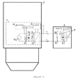
- the converter unit is installed into a garbage truck, 4, in which the current generated from an adequately dimensioned alternator, 11, is rectified, 12, and stored into a battery pack, 13, having in parallel ultracapacitors (or the like), 14, and fast response film capacitors, 18, to provide the correct peak current and to prevent battery ageing.
- the rectified supply current feed a DC to DC converter, 15, which provide the correct constant output current, until the stored quantity of charge reaches a specific voltage level. This is in few seconds or minutes.
- Figures 5 , 6 and 7 show the power connectors system in a waste management application with integrated traceability system.
- the mechanical arm, 6, with the mentioned mechanical jaw, 9, is installed in the rear (or in a side) of a garbage truck.
- the power connectors system consists of two mechanical arms, 6, each of it has a mechanical jaw, 9, at its termination.
- These mechanical jaws, 9, together with terminations, 33, are electrically isolated from the rest of the structure, 8, and they work at the same time as mechanical support and as good electric connectors thanks to the high clamping pressure applied on two bus bar terminations, 33, installed in the garbage box, 36.
- the mechanical jaws also have a tooth shaped profile, 29, which allows a better mechanical clamping and a reduced electrical resistance.
- Figures 6 and 7 show the bus-bars terminations, 33, and wiring 39.
- Figure 8 shows the high efficiency electric energy storage unit which consists of ultracapacitors and film capacitors enclosed into a box, 30, having high grade of electrical, mechanical and chemical isolation. This system is connected by large wires, 31, and provided with integrated voltage sensors, current sensor and thermistor for temperature monitoring, 24.
Landscapes
- Engineering & Computer Science (AREA)
- Mechanical Engineering (AREA)
- Power Engineering (AREA)
- Secondary Cells (AREA)
- Charge And Discharge Circuits For Batteries Or The Like (AREA)
Priority Applications (1)
| Application Number | Priority Date | Filing Date | Title |
|---|---|---|---|
| EP10161235A EP2383859A1 (de) | 2010-04-28 | 2010-04-28 | Elektrische Anlage zum Aufladen schnell isoliert Stromquellen |
Applications Claiming Priority (1)
| Application Number | Priority Date | Filing Date | Title |
|---|---|---|---|
| EP10161235A EP2383859A1 (de) | 2010-04-28 | 2010-04-28 | Elektrische Anlage zum Aufladen schnell isoliert Stromquellen |
Publications (1)
| Publication Number | Publication Date |
|---|---|
| EP2383859A1 true EP2383859A1 (de) | 2011-11-02 |
Family
ID=43427359
Family Applications (1)
| Application Number | Title | Priority Date | Filing Date |
|---|---|---|---|
| EP10161235A Withdrawn EP2383859A1 (de) | 2010-04-28 | 2010-04-28 | Elektrische Anlage zum Aufladen schnell isoliert Stromquellen |
Country Status (1)
| Country | Link |
|---|---|
| EP (1) | EP2383859A1 (de) |
Cited By (4)
| Publication number | Priority date | Publication date | Assignee | Title |
|---|---|---|---|---|
| US20150081959A1 (en) * | 2010-11-02 | 2015-03-19 | Braemar Manufacturing, Llc | Medical data collection apparatus |
| EP3473482A1 (de) * | 2017-10-18 | 2019-04-24 | Terberg Machines B.V. | Mit einem energiemodul ausgestattetes beladungssystem, damit ausgestattetes abfallfahrzeug und verfahren dafür |
| IT201900022092A1 (it) * | 2019-11-25 | 2021-05-25 | Fabrizio Bernini | Sistema di collegamento e ricarica di un cassonetto intelligente e relativo metodo |
| WO2023020983A1 (de) * | 2021-08-16 | 2023-02-23 | S. Franzen Söhne GmbH | Müllbehälter mit einem elektrischen aggregat sowie hebe- oder entleerungsvorrichtung für einen derartigen müllbehälter |
Citations (3)
| Publication number | Priority date | Publication date | Assignee | Title |
|---|---|---|---|---|
| US3656044A (en) * | 1970-10-27 | 1972-04-11 | Ansel A King | Battery charging apparatus |
| WO2004110659A2 (en) * | 2003-06-09 | 2004-12-23 | Seahorse Power Company | Solar powered compaction apparatus |
| GB2442345A (en) * | 2006-09-29 | 2008-04-02 | Milwaukee Electric Tool Corp | Power generating apparatus with battery charger |
-
2010
- 2010-04-28 EP EP10161235A patent/EP2383859A1/de not_active Withdrawn
Patent Citations (3)
| Publication number | Priority date | Publication date | Assignee | Title |
|---|---|---|---|---|
| US3656044A (en) * | 1970-10-27 | 1972-04-11 | Ansel A King | Battery charging apparatus |
| WO2004110659A2 (en) * | 2003-06-09 | 2004-12-23 | Seahorse Power Company | Solar powered compaction apparatus |
| GB2442345A (en) * | 2006-09-29 | 2008-04-02 | Milwaukee Electric Tool Corp | Power generating apparatus with battery charger |
Cited By (8)
| Publication number | Priority date | Publication date | Assignee | Title |
|---|---|---|---|---|
| US20150081959A1 (en) * | 2010-11-02 | 2015-03-19 | Braemar Manufacturing, Llc | Medical data collection apparatus |
| US9907481B2 (en) | 2010-11-02 | 2018-03-06 | Braemar Manufacturing, Llc | System and method for electro-cardiogram (ECG) medical data collection wherein physiological data collected and stored may be uploaded to a remote service center |
| US10034617B2 (en) | 2010-11-02 | 2018-07-31 | Braemar Manufacturing, Llc | System and method for electro-cardiogram (ECG) medical data collection wherein physiological data collected and stored may be uploaded to a remote service center |
| US11331031B2 (en) | 2010-11-02 | 2022-05-17 | Braemar Manufacturing LLC | Medical data collection apparatus |
| EP3473482A1 (de) * | 2017-10-18 | 2019-04-24 | Terberg Machines B.V. | Mit einem energiemodul ausgestattetes beladungssystem, damit ausgestattetes abfallfahrzeug und verfahren dafür |
| NL2019751B1 (nl) * | 2017-10-18 | 2019-04-25 | Terberg Machines | Beladingssysteem voorzien van een energiemodule, vuilnisauto voorzien daarvan en werkwijze daarvoor |
| IT201900022092A1 (it) * | 2019-11-25 | 2021-05-25 | Fabrizio Bernini | Sistema di collegamento e ricarica di un cassonetto intelligente e relativo metodo |
| WO2023020983A1 (de) * | 2021-08-16 | 2023-02-23 | S. Franzen Söhne GmbH | Müllbehälter mit einem elektrischen aggregat sowie hebe- oder entleerungsvorrichtung für einen derartigen müllbehälter |
Similar Documents
| Publication | Publication Date | Title |
|---|---|---|
| KR101893957B1 (ko) | 배터리 팩, 배터리 팩을 포함하는 장치, 및 배터리 팩의 관리 방법 | |
| KR101097264B1 (ko) | 센싱보드가 내장된 배터리팩과 그것을 채용한 전력저장시스템 | |
| US20130328397A1 (en) | Energy storage system | |
| EP3642081B1 (de) | Hilfsstromversorgung für ein fahrzeug | |
| EP2367261A3 (de) | Gleichstromquellenvorrichtung | |
| EP3981638A3 (de) | Vorrichtung und verfahren zum aufladen eines elektrischen fahrzeugs | |
| CN102208827A (zh) | 一种车辆充电系统 | |
| EP2383859A1 (de) | Elektrische Anlage zum Aufladen schnell isoliert Stromquellen | |
| TW201941515A (zh) | 電能分配系統 | |
| US11495974B2 (en) | Modular ultracapacitor energy storage/power delivery apparatus and methods | |
| KR101083818B1 (ko) | 태양 전지 모듈 모니터링 시스템 | |
| KR101599962B1 (ko) | 에너지 저장 시스템 | |
| US20220398675A1 (en) | Smart Energy Management System (SEMS) | |
| US20050226021A1 (en) | System and methods for generating mobile power | |
| KR20130125704A (ko) | 전력 축적 시스템, 및, 축전 모듈의 제어 방법 | |
| Obreja | On the performance of commercial supercapacitors as storage devices for renewable electrical energy sources | |
| RU2615985C1 (ru) | Автономный интеллектуальный источник питания | |
| Oltean et al. | A supercapacitor stack-design and characteristics | |
| KR100910428B1 (ko) | 균등 충전 단자를 포함한 울트라 커패시터 모듈 | |
| CN201937321U (zh) | 一种车载电子设备的供电装置及车载电子设备 | |
| Abed et al. | Experimental study of battery state of charge effect on battery charging/discharging performance and battery output power in pv energy system | |
| Moungngam et al. | Applied supercapacitor to energy storage during regenerative brake state in electric vehicle | |
| US12451720B2 (en) | Hybrid capacitor energy storage | |
| JP2006129621A (ja) | 電源装置 | |
| CN216056445U (zh) | 一种卫星蓄电池标准模组 |
Legal Events
| Date | Code | Title | Description |
|---|---|---|---|
| AK | Designated contracting states |
Kind code of ref document: A1 Designated state(s): AT BE BG CH CY CZ DE DK EE ES FI FR GB GR HR HU IE IS IT LI LT LU LV MC MK MT NL NO PL PT RO SE SI SK SM TR |
|
| AX | Request for extension of the european patent |
Extension state: AL BA ME RS |
|
| PUAI | Public reference made under article 153(3) epc to a published international application that has entered the european phase |
Free format text: ORIGINAL CODE: 0009012 |
|
| STAA | Information on the status of an ep patent application or granted ep patent |
Free format text: STATUS: THE APPLICATION IS DEEMED TO BE WITHDRAWN |
|
| 18D | Application deemed to be withdrawn |
Effective date: 20120503 |