EP2384029A2 - Génération de signaux pour signaux binauraux - Google Patents
Génération de signaux pour signaux binauraux Download PDFInfo
- Publication number
- EP2384029A2 EP2384029A2 EP11168514A EP11168514A EP2384029A2 EP 2384029 A2 EP2384029 A2 EP 2384029A2 EP 11168514 A EP11168514 A EP 11168514A EP 11168514 A EP11168514 A EP 11168514A EP 2384029 A2 EP2384029 A2 EP 2384029A2
- Authority
- EP
- European Patent Office
- Prior art keywords
- channels
- channel
- signal
- downmix
- binaural
- Prior art date
- Legal status (The legal status is an assumption and is not a legal conclusion. Google has not performed a legal analysis and makes no representation as to the accuracy of the status listed.)
- Granted
Links
Images





Classifications
-
- H—ELECTRICITY
- H04—ELECTRIC COMMUNICATION TECHNIQUE
- H04S—STEREOPHONIC SYSTEMS
- H04S7/00—Indicating arrangements; Control arrangements, e.g. balance control
-
- H—ELECTRICITY
- H04—ELECTRIC COMMUNICATION TECHNIQUE
- H04S—STEREOPHONIC SYSTEMS
- H04S3/00—Systems employing more than two channels, e.g. quadraphonic
- H04S3/002—Non-adaptive circuits, e.g. manually adjustable or static, for enhancing the sound image or the spatial distribution
- H04S3/004—For headphones
-
- H—ELECTRICITY
- H04—ELECTRIC COMMUNICATION TECHNIQUE
- H04S—STEREOPHONIC SYSTEMS
- H04S5/00—Pseudo-stereo systems, e.g. in which additional channel signals are derived from monophonic signals by means of phase shifting, time delay or reverberation
-
- H—ELECTRICITY
- H04—ELECTRIC COMMUNICATION TECHNIQUE
- H04S—STEREOPHONIC SYSTEMS
- H04S7/00—Indicating arrangements; Control arrangements, e.g. balance control
- H04S7/30—Control circuits for electronic adaptation of the sound field
-
- H—ELECTRICITY
- H04—ELECTRIC COMMUNICATION TECHNIQUE
- H04S—STEREOPHONIC SYSTEMS
- H04S2400/00—Details of stereophonic systems covered by H04S but not provided for in its groups
- H04S2400/01—Multi-channel, i.e. more than two input channels, sound reproduction with two speakers wherein the multi-channel information is substantially preserved
-
- H—ELECTRICITY
- H04—ELECTRIC COMMUNICATION TECHNIQUE
- H04S—STEREOPHONIC SYSTEMS
- H04S2420/00—Techniques used stereophonic systems covered by H04S but not provided for in its groups
- H04S2420/01—Enhancing the perception of the sound image or of the spatial distribution using head related transfer functions [HRTF's] or equivalents thereof, e.g. interaural time difference [ITD] or interaural level difference [ILD]
Definitions
- the human auditory system is able to determine the direction or directions where sounds perceived come from. To this end, the human auditory system evaluates certain differences between the sound received at the right hand ear and sound received at the left hand ear.
- the latter information comprises, for example, so-called inter-aural cues which may, in turn, refer to the sound signal difference between ears. Inter-aural cues are the most important means for localization.
- the pressure level difference between the ears namely the inter-aural level difference (ILD) is the most important single cue for localization.
- ILD inter-aural level difference
- the so-called head-related transfer functions contain the directional information including the interaural cures.
- HRTFs head-related transfer functions
- a common processing block is used to model the room reflections and reverberation.
- the room processing module can be a reverberation algorithm in time or frequency domain, and may operate on a one or two channel input signal obtained from the multi-channel input signal by means of a sum of the channels of the multi-channel input signal.
- the room processing block implements room reflections and/or reverberation. Room reflections and reverberation are essential to localized sounds, especially with respect to distance and externalization-meaning sounds are perceived outside the listener's head.
- the aforementioned document also suggests implementing the directional filters as a set of FIR filters operating on differently delayed versions of the respective channel, so as to model the direct path from the sound source to the respective ear and distinct reflections.
- the first idea underlying the present application is that a more stable and pleasant binaural signal for headphone reproduction may be achieved by differently processing, and thereby reducing the similarity between, at least one of a left and a right channel of the plurality of input channels, a front and a rear channel of the plurality of input channels, and a center and a non-center channel of the plurality of channels, thereby obtaining an inter-similarity reduced set of channels.
- This inter-similarity reduced set of channels is then fed to a plurality of directional filters followed by respective mixers for the left and the right ear, respectively.
- the similarity reducer 12 is configured to turn the multi-channel signal 18 representing the plurality of channels 18a-18d, into an inter- similarity reduced set 20 of channels 20a-20d.
- the number of channels 18a-18d represented by the multi-channel signal 18 may be two or more. For illustration purposes only, four channels 18a-18d have explicitly been shown in Fig. 1 .
- the plurality 18 of channels may, for example, comprise a center channel, a front left channel, a front right channel, a rear left channel, and a rear right channel.
- the plurality of channels 18a-18d comprises, at least, a pair of a left and a right channel, a pair of a front and a rear channel, or a pair of a center and a non-center channel.
- the similarity reducer 12 is configured to differently process, and thereby reduce a similarity between channels of the plurality of channels. , in order to obtain the inter- similarity reduced set 20 of channels 20a-20d.
- the similarity reducer 12 may also achieve the different processing by subjecting the respective pairs of channels to level reductions of different amounts in, for example, each of a plurality of frequency bands, thereby obtaining an inter-similarity reduced set 20 of channels in a spectrally formed way.
- the spectral formation may, for example, exaggerate the relative spectrally formed reduction occurring, for example, for rear channel sound relative to front channel sound due to the shadowing by the earlap.
- the directional filters 14a-14h are configured to model an acoustic transmission of a respective one of channels 20a-20d from a virtual sound source position associated with the respective channel to a respective ear canal of the listener.
- directional filters 14a-14d model the acoustic transmission to, for example, the left ear canal
- directional filters 14e-14h model the acoustic transmission to the right ear canal.
- the directional filters may model the acoustic transmission from a virtual sound source position in a room to an ear canal of the listener and may perform this modeling by performing time, level and spectral modifications, and optionally, modeling room reflections and reverberation.
- the directional filters 18a-18h may be implemented in time or frequency domain.
- the directional filters may be time-domain filters such as filters, FIR filters, or may operate on the frequency domain by multiplying respective transfer function sample values with respective spectral values of channels 20a-20d.
- the directional filters 14a-14h may be selected to model the respective head-related transfer function describing the interaction of the respective channel signal 20a-20d from the respective virtual sound source position to the respective ear canal, including, for example, the interactions with the head, ears, and shoulders of a human person.
- the first mixer 16a is configured to mix the outputs of the directional filters 14a-14d modeling the acoustic transmission to the left ear canal of the listener to obtain a signal 22a intended to contribute to, or even be the left channel of the binaural output signal
- the second mixer 16b is configured to mix the outputs of the directional filters 14e-14h modeling the acoustic transmission to the right ear canal of the listener to obtain a signal 22b, and intended to contribute to or even be the right channel of the binaural output signal.
- Fig. 1 shows, in other words, a signal flow for the generation of a headphone output from, for example, a decoded multi-channel signal.
- Each signal is filtered by a pair of directional filter pairs.
- channel 18a is filtered by the pair of directional filters 14a-14e.
- a significant amount of similarity such as correlation exists between channels 18a-18d in typical multi-channel sound productions. This would negatively affect the binaural output signal.
- the intermediate signals output by the directional filters 14a-14h are added in mixer 16a and 16b to form the headphone output signal 20a and 20b.
- Fig. 2 shows a device for forming an inter-similarity decreasing set of head-related transfer functions for modeling an acoustic transmission of a set of channels from a virtual sound source position associated with the respective channel to the ear canals of a listener.
- the device which is generally indicated by 30 comprises an HRTF provider 32, as well as an HRTF processor 34.
- the HRTF processor 34 is configured to cause the impulse responses of at least a pair of the HRTFs to be displaced relative to each other or modify- in a spectrally varying sense - the phase and/or magnitude responses thereof differently relative to each other.
- the pair of HRTFs may model the acoustic transmission of one of left and right channels, front and rear channels, and center and non-center channels.
- the inter-similarity decreasing set of HRTFs resulting from the HRTF processor 34 may be used for setting the HRTFs of the directional filters 14a-14h of the device of Fig. 1 , wherein the similarity reducer 12 may be present or absent. Due to the dis-similarity property of the modified HRTFs, the aforementioned advantages with respect to the spatial width of the binaural output signal and the improved externalization is similarly achieved even when the similarity reducer 12 is missing.
- the idea underlying the room processor 44 is that the room reflection/reverberation which occurs in, for example, a room, may be modeled in a manner transparent for the listener, based on a downmix such as a simple sum of the channels of the multi-channel signal 18. Since the room reflections/ reverberation occur later than sounds traveling along the direct path or line of sight from the sound source to the ear canals, the room processor's impulse response is representative for, and substitutes, the tail of the impulse responses of the directional filters shown in Fig. 1 .
- the impulse responses of the directional filters may, in turn, be restricted to model the direct path and the reflection and attenuations occurring at the head, ears, and shoulders of the listener, thereby enabling shortening the impulse responses of the directional filters.
- the border between what is modeled by the directional filter and what is modeled by the room processor 44 may be freely varied so that the directional filter may, for example, also model the first room reflections/reverberation.
- the room processor comprises four reverberation filters 50a-50d.
- the inputs of reverberation filters 50a and 50b are connected to a first channel 48a of the stereo downmix 48, whereas the input of the reverberation filters 50c and 50d are connected to the other channel 48b of the stereo downmix 48.
- the outputs of reverberation filters 50a and 50c are connected to the input of an adder 52a, the output of which provides the left channel contribution 46a.
- the output of reverberation filters 50b and 50d are connected to inputs of a further adder 52b, the output of which provides the right channel contribution 46b.
- the downmix generator 42 may simply sum the channels of the multi-channel signal 18-with weighing each channel equally-, this is not exactly the case with the embodiment of Fig. 3 . Rather, the downmix generator 42 of Fig. 3 is configured to form the mono or stereo downmix 48, such that the plurality of channels contribute to the mono or stereo downmix at a level differing among at least two channels of the multi-channel signal 18.
- certain contents of multi-channel signals such as speech or background music which are mixed into a specific channel or specific channels o the multi-channel signal, may be prevented from or encouraged to being subject to the room processing, thereby avoiding a unnatural sound.
- the downmix generator 42 forms a weighted sum of the channels of the channels of the multi-channel signal 18, with the weighting value associated with the center channel being reduced relative to the weighting values of the other channels.
- the downmix generator 42 may be configured to detect voice phases or distinguish these voice phases from non-voice phases, or may assign a voice content measure measuring the voice content, being of at least ordinal scale, to consecutive frames of the center channel. For example, the downmix generator 42 detects the presence of voice in the center channel by means of a voice filter and determines as to whether the output level of this filter exceeds the sum threshold.
- the detection of voice phases within the center channel by the downmix generator 42 is not the only way to make the afore-mentioned mode switching of level reduction amount variation time-dependent.
- the multi-channel signal 18 could have side information associated therewith, which is especially intended for distinguishing between voice phases and non-voice phases, or measuring the voice content quantitatively.
- the multi-channel signal 18 may also comprise downmixing information describing the ratios by which the individual channels have been mixed into the downmix signal 62, or the individual channels of the downmix signal 62, as the downmix channel 62 may for example be a normal downmix signal 62 or a stereo downmix signal 62.
- the downmix generator 42 of Fig. 5 comprises a decoder 64 and a mixer 66.
- the decoder 64 decodes, according to spatial audio decoding, the multi-channel signal 18 in order to obtain the plurality of channels including, inter alia, the center channel 66, and other channels 68.
- the mixer 66 is configured to mix the center channel 66 and the other non-center channels 68 to derive the mono or stereo signal 48 by performing the afore-mentioned level reduction. As indicated by the dashed line 70, the mixer 66 may be configured to use the spatial parameter 64 in order to switch between the level reduction mode and the non-level reduction mode of the varied amount of level reduction, as mentioned above.
- the spatial parameter 64 used by the mixer 66 may, for example, be channel prediction coefficients describing how the center channel 66, a left channel or the right channel may be derived from the downmix signal 62, wherein mixer 66 may additionally use inter-channel coherence/cross-correlation parameters representing the coherence or cross-correlation between the just-mentioned left and right channels which, in turn, may be downmixes of front left and rear left channels, and front right and rear right channels, respectively.
- the center channel may be mixed at a fixed ratio into the afore-mentioned left channel and the right channel of the stereo downmix signal 62.
- two channel prediction coefficients are sufficient in order to determine how the center, left, and right channels may be derived from a respective linear combination of the two channels of the stereo downmix signal 62.
- the mixer 66 may use a ratio between a sum and a difference of the channel prediction coefficients in order to differentiate between voice phases and non-voice phases.
- level reduction with respect to the center channel has been described in order to exemplify the weighted summation of the plurality of channels such that same contribute to the mono or stereo downmix at a level differing among at least two channels of the multi-channel signal 18, there are also other examples where other channels are advantageously level-reduced or level-amplified relative to another channel or other channels because some sound source content present in this or these channels is/are to, or is/are not to, be subject to the room processing at the same level as other contents in the multi-channel signal but at a reduced/increased level.
- the downmix signal 62 comprises a sequence of spectral values 88 per subband 82.
- the time resolution at which the subbands 82 are sampled by the sample values 88 may be defined by filterbank slots 90.
- the time slots 90 and subbands 82 define some time/frequency resolution or grid.
- a coarser time/frequency grid is defined by uniting neighboring sample values 88 to time/frequency tiles 92 as indicated by the dashed lines in Fig. 6 , these tiles defining the time/frequency parameter resolution or grid.
- the aforementioned spatial parameters 62 are defined in that time/frequency parameter resolution 92.
- the time/frequency parameter resolution 92 may change in time.
- the multi-channel signal 62 may be divided-up into consecutive frames 94.
- the time/frequency resolution grid 92 is able to be set individually.
- decoder 64 may comprise of an internal analysis filterbank in order to derive the representation of the downmix signal 62 as shown in Fig. 6 .
- downmix signal 62 enters the decoder 64 in the form as shown in Fig. 6 , in which case no analysis filterbank is necessary in decoder 64.
- two channel prediction coefficients may be present revealing how, with respect to the respective time/frequency tile 92, the right and left channels may be derived from the left and right channels of the stereo downmix signal 62.
- an inter-channel coherence/cross-correlation (ICC) parameter may be present for tile 92 indicating the ICC similarities between the left and right channel to be derived from the stereo downmix signal 62, wherein one channel has been completely mixed into one channel of the stereo downmix signal 62, while the other has completely been mixed into the other channel of the stereo downmix signal 62.
- a channel level difference (CLD) parameter may further be present for each tile 92 indicating the level difference between the just-mentioned left and right channels.
- a non-uniform quantization on a logarithmic scale may be applied to the CLD parameters, where the quantization has a high accuracy close to zero dB and a coarser resolution when there is a large difference in level between the channels.
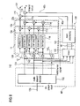
- a mixer 120 and a room processor 122 are connected in series between the output of the multi-channel decoder 102 and the respective input of adders 16 and 118, the outputs of which define the binaural output signal output at output 104.
- the device of Fig. 7 uses a signal flow for the generation of a headphone output at output 104 from a decoded multi-channel signal 124.
- the decoded multi-channel 124 is derived by the multi-channel decoder 102 from a bitstream input at a bitstream input 126, such as, for example, by spatial audio decoding.
- each signal or channel of the decoded multi-channel signal 124 is filtered by a pair of directional filters 110.
- the first (upper) channel of the decoded multi-channel signal 124 is filtered by directional filters 20 DirFilter(1,L) and DirFilter(1,R), and a second (second from the top) signal or channel is filtered by directional filter DirFilter(2,L) and DirFilter(2,R), and so on.
- These filters 110 may model the acoustical transmission from a virtual sound source in a room to the ear canal of a listener, a so-called binaural room transfer function (BRTF). They may perform time, level, and spectral modifications, and may partially also model room reflection and reverberation.
- the directional filters 110 may be implemented in time or frequency domains.
- multi-channel sound is produced such that the dominating sound energy is contained in the front channels, i.e. left front, right front, center.
- Voices in movie dialogs and music are typically mixed mainly to the center channel.
- the center channel is fed to the room processing module 122 with a significant level reduction, such as attenuated by 6 dB, which level reduction is performed, as already denoted above, within mixer 120.
- the embodiment of Fig. 7 comprises a configuration according to Figs. 3 and 5 , wherein reference signs 102, 124, 120, and 122 of Fig. 7 correspond to reference signs 18, 64, the combination of reference signs 66 and 68, reference sign 66 and reference sign 44 of Figs. 3 and 5 , respectively.
- the amount of delay caused by each of the delays 142 1- 142 4 would be different to each other.
- the decorrelators 142 1 -142 4 are all-pass filters, i.e. filters having a transfer function of a magnitude of constantly being one with, however, changing the phases of the spectral components of the respective channel.
- the phase modifications caused by the decorrelators 142 1 -142 4 would preferably be different for each of the channels.
- the decorrelator 142 1 -142 4 could be implemented as FIR filters, or the like.
- the elements 142 1 -142 4 , 110, 112, and 114 act in accordance with the device 10 of Fig. 1 .
- Fig. 9 shows a variation of the binaural output signal generator of Fig. 7 .
- Fig. 9 is also explained below using the same reference signs as used in Fig. 7 .
- the level reduction of mixer 122 is merely optional in the case of Fig. 9 , and therefore, reference sigh 40' has been in Fig. 9 rather than '40, as was the case in Fig. 7 .
- the embodiment of Fig. 9 addresses the problem that significant correlation exists between all channels in multi-channel sound productions.
- the two-channel intermediate signals of each filter pair are added by adders 112 and 114, to form the headphone output signal at output 104.
- the summation of correlated output signals by adders 112 and 114 results in a greatly reduced spatial width of the output signal at output 104, and a lack of an externalization. This is particularly problematic for the correlation of the left and right signal and the center channel within decoded multi-channel signal 124.
- the directional filters are configured to have a decorrelated output as far as possible. To this end, the device of Fig.
- Figs. 7 to 9 concerned a decoded multi-channel signal.
- the following embodiments are concerned with the parametric multi-channel decoding for headphones.
- spatial audio coding is a multi-channel compression technique that exploits the perceptual inter-channel irrelevance in multi-channel audio signals to achieve higher compression rates.
- This can be captured in terms of spatial cues or spatial parameters, i.e. parameters describing the spatial image of a multi-channel audio signal.
- Spatial cues typically include level/intensity differences, phase differences and measures of correlations/coherence between channels, and can be represented in an extremely compact manner.
- the concept of spatial audio coding has been adopted by MPEG resulting in the MPEG surround standard, i.e. ISO/I1EC23003-1.
- Spatial parameters such as those employed in spatial audio coding can also be employed to describe directional filters. By doing so, the step of decoding spatial audio data and applying directional filters can be combined to efficiently decode and render multi-channel audio for headphone reproduction.
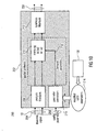
- the general structure of a spatial audio decoder for headphone output is given in Fig. 10 .
- the decoder of Fig. 10 is generally indicated with reference sign 200, and comprises a binaural spatial subband modifier 202 comprising an input for a stereo or mono downmix signal 204, another input for spatial parameters 206, and an output for the binaural output signal 208.
- the downmix signal along with the spatial parameters 206 form the afore-mentioned multi-channel signal 18 and represent the plurality of channels thereof.
- the downmix signal is assumed to have already been decoded beforehand, including for example, entropy encoding.
- the binaural spatial audio decoder is fed with the downmix signal 204.
- the parameter converter 214 uses the spatial parameters 206 and parametric description of the directional filters in the form of the modified HRTF parameter 216 to form binaural parameters 218. These parameters 218 are applied by matrixing unit 210 in from of a two-by-two matrix (in case of a stereo downmix signal) and in form of a one-by-two matrix (in case of a mono downmix signal 204), in frequency domain, to the spectral values 88 output by analysis filterbank 208 (see Fig. 6 ).
- the binaural parameters 218 vary in the time/frequency parameter resolution 92 shown in Fig. 6 and are applied to each sample value 88. Interpolation may be used to smooth the matrix coefficients and the binaural parameters 218, respectively, from the coarser time/frequency parameter domain 92 to the time/frequency resolution of the analysis filterbank 208. That is, in the case of a stereo downmix 204, the matrixing performed by unit 210 results in two sample values per pair of sample value of the left channel of the downmix signal 204 and the corresponding sample value of the right channel of the downmix signal 204. The resulting two sample values are part of the left and right channels of the binaural output signal 208, respectively.
- the matrixing by unit 210 results in two sample values per sample value of the mono downmix signal 204, namely one for the left channel and one for the right channel of the binaural output signal 208.
- the binaural parameters 218 define the matrix operation leading from the one or two sample values of the downmix signal 204 to the respective left and right channel sample values of the binaural output signal 208.
- the binaural parameters 218 already reflect the modified HRTF parameters. Thus, they decorrelate the input channels of the multi-channel signal 18 as indicated above.
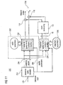
- the downmix audio decoder 232 is connected between a bitstream input 126 and a binaural spatial audio subband modifier 202 of the binaural spatial audio decoder 200'.
- the downmix audio decoder 232 is configured to decode the bit stream input at input 126 to derive the downmix signal 214 and the spatial parameters 206.
- Both, the binaural spatial audio subband modifier 202, as well as the modified spatial audio subband modifier 234 is provided with a downmix signal 204 in addition to the spatial parameters 206.
- the modified spatial audio subband modifier 234 computes from the downmix signal 204 - by use of the spatial parameters 206 as well as modified parameters 236 reflecting the aforementioned amount of level reduction of the center channel - the mono or stereo downmix 48 serving as an input for room processor 122.
- the contributions output by both the binaural spatial audio subband modifier 202 and the room processor 122, respectively, are channel-wise summed in adders 116 and 118 to result in the binaural output signal at output 238.
- Fig. 12 shows a block diagram illustrating the functionality of the binaural audio decoder 200' of Fig. 11 . It should be noted that Fig. 12 does not show the actual internal structure of the binaural spatial audio decoder 200' of Fig. 11 , but illustrates the signal modifications obtained by the binaural spatial audio decoder 200'. It is recalled that the internal structure of the binaural spatial audio decoder 200' generally complies with the structure shown in Fig. 10 , with the exception that the device 30 may be left away in the case that same is operating with the original HRTFs. Additionally, Fig.
- FIG. 12 shows the functionality of the binaural spatial audio decoder 200' exemplarily for the case that only three channels represented by the multi-channel signal 18 are used by the binaural spatial audio decoder 200' in order to form the binaural output signal 208.
- a "2 to 3", i.e. TTT, box is used to derive a center channel 242, a right channel 244, and a left channel 246 from the two channels of the stereo downmix 204.
- Fig. 12 exemplarily assumes that the downmix 204 is a stereo downmix.
- the spatial parameters 206 used by the TTT box 248 comprise the abovementioned channel prediction coefficients.
- the correlation reduction is achieved by three decorrelators, denoted DelayL, DelayR, and DelayC in Fig. 12 . They correspond to the decorrelation introduced in case of, for example, Figs. 1 and 7 .
- Fig. 12 merely shows the signal modifications achieved by the binaural spatial audio decoder 200', although the actual structure corresponds to that shown in Fig. 10 .
- the delays forming the correlation reducer 12 are shown as separate features relative to the HRTFs forming the directional filters 14, the existence of the delays in the correlation reducer 12 may be seen as a modification of the HRTF parameters forming the original HRTFs of the directional filters 14 of Fig. 12 .
- Fig. 13 shows an example for a structure of the modified spatial audio subband modifier of Fig. 11 .
- the subband modifier 234 of Fig. 13 comprises a two-to-three or TTT box 262, weighting stages 264a-264e, first adders 266a and 266b, second adders 268a and 268b, an input for the stereo downmix 204, an input for the spatial parameters 206, a further input for a residual signal 270 and an output for the downmix 48 intended for being processed by the room processor, and being, in accordance with Fig. 13 , a stereo signal.
- the TTT box 262 of Fig. 13 merely reconstructs the center channel, the right channel 244, and the left channel 246 from the stereo downmix 204 by using the spatial parameters 206. It is once again recalled that in the case of Fig. 12 , the channels 242-246 are actually not computed. Rather, the binaural spatial audio subband modifier modifies matrix M in such a manner that the stereo downmix signal 204 is directly turned into the binaural contribution reflecting the HRTFs. The TTT box 262 of Fig. 13 , however, actually performs the reconstruction. Optionally, as shown in Fig.
- the TTT box 262 may use a residual signal 270 reflecting the prediction residual when reconstructing channels 242-246 based on the stereo downmix 204 and the spatial parameters 206, which as denoted above, comprise the channel prediction coefficients and, optionally, the ICC values.
- the first adders 266a are configured to add-up channels 242-246 to form the left channel of the stereo downmix 48.
- a weighted sum is formed by adders 266a and 266b, wherein the weighting values are defined by the weighting stages 264a, 264b, 264c, and 264e which might apply to the respective channel 246 to 242, a respective weighting value EQ LL , EQ RL and EQ CL .
- adders 268a and 268b form a weighted sum of channels 246 to 242 with weighting stages 264b, 264d, and 264e forming the weighting values, the weighted sum forming the right channel of the stereo downmix 48.
- the parameters 270 for the weighting stages 264a-264e are, as described above, selected such that the above-described center channel level reduction in the stereo downmix 48 is achieved resulting, as described above, in the advantages with respect to natural sound perception.
- Fig. 13 shows a room processing module which may be applied in combination with the binaural parametric decoder 200' of Fig. 12 .
- the downmix signal 204 is used to feed the module.
- the downmix signal 204 contains all the signals of the multi-channel signal to be able to provide stereo compatibility.
- the modified spatial audio subband modifier of Fig. 13 serves to perform this level reduction.
- a residual signal 270 may be used in order to reconstruct the center, left and right channels 242-246.
- the residual signal of the center and the left and right channels 242-246 may be decoded by the downmix audio decoder 232, although not shown in Fig. 11 .
- the EQ parameters or weighting values applied by the weighting stages 264a-264e may be real-valued for the left, right, and center channels 242-246.
- a single parameter set for the center channel 242 may be stored and applied, and the center channel is, according to Fig. 13 , exemplarily equally mixed to both, left and right output of stereo downmix 48.
- the EQ parameters 270 fed into the modified spatial audio subband modifier 234 may have the following properties. Firstly, the center channel signal may be attenuated preferably by at least 6 dB. Further, the center channel signal may have a low-pass characteristic. Even further, the difference signal of the remaining channels may be boosted at low frequencies. In order to compensate the lower level of the center channel 242 relative to the other channels 244 and 246, the gain of the HRTF parameters for the center channel used in the binaural spatial audio subband modifier 202 should be increased accordingly.
- the main goal of the setting of the EQ parameters is the reduction of the center channel signal in the output for the room processing module.
- the center channel should only be suppressed to a limited extent: the center channel signal is subtracted from the left and the right downmix channels inside the TTT box. If the center level is reduced, artifacts in the left and right channel may become audible. Therefore, center level reduction in the EQ stage is a trade-off between suppression and artifacts. Finding a fixed setting of EQ parameters is possible, but may not be optimal for all signals. Accordingly, according to an embodiment, an adaptive algorithm or module 274 may be used to control the amount of center level reduction by one, or a combination of the following parameters:
- the spatial parameters 206 used to decode the center channel 242 from the left and right downmix channel 204 inside the TTT box 262 may be used as indicated by dashed line 276.
- the level of center, left and right channels may be used as indicated by dashed line 278.
- center, left and right channels 242-246 may be used as also indicated by dashed line 278.
- the output of a single-type detection algorithm such as a voice activity detector, may be used as also indicated by dashed line 278.
- static of dynamic metadata describing the audio content may be used in order to determine the amount of center level reduction as indicated by dashed line 280.
- aspects described in the context of an apparatus it is clear that these aspects also represent a description of the corresponding method, wherein a block or device corresponds to a method step or a feature of a method step.
- aspects described in the context of a method step also represent a description of a corresponding block or item or feature of a corresponding apparatus such as a part of an ASIC, a sub-routine of a program code or a part of a programmed programmable logic.
- the inventive encoded audio signal can be stored on a digital storage medium or can be transmitted on a transmission medium such as a wireless transmission medium or a wired transmission medium such as the Internet.
- embodiments of the invention can be implemented in hardware or in software.
- the implementation can be performed using a digital storage medium, for example a floppy disk, a DVD, a CD, a ROM, a PROM, an EPROM, an EEPROM or a FLASH memory, having electronically readable control signals stored thereon, which cooperate (or are capable of cooperating) with a programmable computer system such that the respective method is performed.
- a digital storage medium for example a floppy disk, a DVD, a CD, a ROM, a PROM, an EPROM, an EEPROM or a FLASH memory, having electronically readable control signals stored thereon, which cooperate (or are capable of cooperating) with a programmable computer system such that the respective method is performed.
- Some embodiments according to the invention comprise a data carrier having electronically readable control signals, which are capable of cooperating with a programmable computer system, such that one of the methods described herein is performed.
- embodiments of the present invention can be implemented as a computer program product with a program code, the program code being operative for performing one of the methods when the computer program product runs on a computer.
- the program code may for example be stored on a machine readable carrier.
- a further embodiment of the inventive method is, therefore, a data stream or a sequence of signals representing the computer program for performing one of the methods described herein.
- the data stream or the sequence of signals may for example be configured to be transferred via a data communication connection, for example via the Internet.
- a further embodiment comprises a processing means, for example a computer, or a programmable logic device, configured to or adapted to perform one of the methods described herein.
- a processing means for example a computer, or a programmable logic device, configured to or adapted to perform one of the methods described herein.
- a further embodiment comprises a computer having installed thereon the computer program for performing one of the methods described herein.
- a device for generating a binaural signal based on a multi-channel signal representing a plurality of channels and intended for reproduction by a speaker configuration having a virtual sound source position associated to each channel comprising a similarity reducer 12 for performing - in a spectrally varying sense - a phase and/or magnitude modification differently between at least two channels of the plurality of channels, in order to obtain an inter-similarity reduced set 20 of channels; a plurality 14 of directional filters for modeling an acoustic transmission of a respective one of the inter-similarity reduced set 20 of channels from a virtual sound source position associated with the respective channel of the inter- similarity reduced set of channels to a respective ear canal of a listener; a first mixer 16a for mixing outputs of the directional filters modeling the acoustic transmission to the first ear canal of the listener to obtain a first channel 22a of the binaural signal; and a second mixer 16b for mixing outputs of the directional filters
- a device for generating a room reflection/reverberation related contribution of a binaural signal based on a multi-channel signal representing a plurality of channels and being intended for reproduction by a speaker configuration having a virtual sound source position associated to each channel comprising: a downmix generator forming a mono or stereo downmix of the channels of the multi-channel signal; and a room processor for generating the room-reflections/reverberation related contribution of the binaural signal by modeling room reflections/reverberations based on the mono or stereo signal, wherein the downmix generator is configured to form the mono or stereo downmix such that the plurality of channels contribute to the mono or stereo downmix at a level differing among at least two channels of the multi-channel signal.
- the device may further comprise a signal-type detector for detecting speech and non-speech phases within the multi-channel signal, wherein the downmix generator is configured to perform the formation such that an amount of level-reduction is higher during speech phases than during non-speech phases.
- the above-described embodiments also described respective methods for generating a binaural signal based on a multi-channel signal representing a plurality of channels and intended for reproduction by a speaker configuration having a virtual sound source position associated to each channel, and a respective method for forming an inter-similarity decreasing set of head-related transfer functions for modeling an acoustic transmission of a plurality of channels from a virtual sound source position associated with the respective channel to ear canals of a listener.
Landscapes
- Physics & Mathematics (AREA)
- Engineering & Computer Science (AREA)
- Acoustics & Sound (AREA)
- Signal Processing (AREA)
- Stereophonic System (AREA)
Priority Applications (1)
| Application Number | Priority Date | Filing Date | Title |
|---|---|---|---|
| PL11168514T PL2384029T3 (pl) | 2008-07-31 | 2009-07-30 | Generowanie sygnału dla sygnałów dwuusznych |
Applications Claiming Priority (2)
| Application Number | Priority Date | Filing Date | Title |
|---|---|---|---|
| US8528608P | 2008-07-31 | 2008-07-31 | |
| EP09777567.0A EP2304975B1 (fr) | 2008-07-31 | 2009-07-30 | Génération de signal pour des signaux binauraux |
Related Parent Applications (3)
| Application Number | Title | Priority Date | Filing Date |
|---|---|---|---|
| EP09777567.0A Division-Into EP2304975B1 (fr) | 2008-07-31 | 2009-07-30 | Génération de signal pour des signaux binauraux |
| EP09777567.0A Division EP2304975B1 (fr) | 2008-07-31 | 2009-07-30 | Génération de signal pour des signaux binauraux |
| EP09777567.0 Division | 2009-07-30 |
Publications (3)
| Publication Number | Publication Date |
|---|---|
| EP2384029A2 true EP2384029A2 (fr) | 2011-11-02 |
| EP2384029A3 EP2384029A3 (fr) | 2012-10-24 |
| EP2384029B1 EP2384029B1 (fr) | 2014-09-10 |
Family
ID=41107586
Family Applications (3)
| Application Number | Title | Priority Date | Filing Date |
|---|---|---|---|
| EP09777567.0A Active EP2304975B1 (fr) | 2008-07-31 | 2009-07-30 | Génération de signal pour des signaux binauraux |
| EP11168514.5A Active EP2384029B1 (fr) | 2008-07-31 | 2009-07-30 | Génération de signaux pour signaux binauraux |
| EP11168513.7A Active EP2384028B1 (fr) | 2008-07-31 | 2009-07-30 | Génération de signaux pour signaux binauraux |
Family Applications Before (1)
| Application Number | Title | Priority Date | Filing Date |
|---|---|---|---|
| EP09777567.0A Active EP2304975B1 (fr) | 2008-07-31 | 2009-07-30 | Génération de signal pour des signaux binauraux |
Family Applications After (1)
| Application Number | Title | Priority Date | Filing Date |
|---|---|---|---|
| EP11168513.7A Active EP2384028B1 (fr) | 2008-07-31 | 2009-07-30 | Génération de signaux pour signaux binauraux |
Country Status (12)
| Country | Link |
|---|---|
| US (1) | US9226089B2 (fr) |
| EP (3) | EP2304975B1 (fr) |
| JP (2) | JP5746621B2 (fr) |
| KR (3) | KR101366997B1 (fr) |
| CN (3) | CN103634733B (fr) |
| AU (1) | AU2009275418B9 (fr) |
| BR (1) | BRPI0911729B1 (fr) |
| CA (3) | CA2732079C (fr) |
| ES (3) | ES2531422T3 (fr) |
| PL (3) | PL2304975T3 (fr) |
| RU (1) | RU2505941C2 (fr) |
| WO (1) | WO2010012478A2 (fr) |
Families Citing this family (77)
| Publication number | Priority date | Publication date | Assignee | Title |
|---|---|---|---|---|
| US7711123B2 (en) * | 2001-04-13 | 2010-05-04 | Dolby Laboratories Licensing Corporation | Segmenting audio signals into auditory events |
| RU2011130551A (ru) * | 2008-12-22 | 2013-01-27 | Конинклейке Филипс Электроникс Н.В. | Формирование выходного сигнала посредством обработки сенд-эффектов |
| WO2012093352A1 (fr) | 2011-01-05 | 2012-07-12 | Koninklijke Philips Electronics N.V. | Système audio et son procédé de fonctionnement |
| KR101842257B1 (ko) * | 2011-09-14 | 2018-05-15 | 삼성전자주식회사 | 신호 처리 방법, 그에 따른 엔코딩 장치, 및 그에 따른 디코딩 장치 |
| KR101651419B1 (ko) | 2012-03-23 | 2016-08-26 | 돌비 레버러토리즈 라이쎈싱 코오포레이션 | 머리 전달 함수들의 선형 믹싱에 의한 머리 전달 함수 생성을 위한 방법 및 시스템 |
| JP5949270B2 (ja) * | 2012-07-24 | 2016-07-06 | 富士通株式会社 | オーディオ復号装置、オーディオ復号方法、オーディオ復号用コンピュータプログラム |
| EP2939443B1 (fr) | 2012-12-27 | 2018-02-14 | DTS, Inc. | Système et procédé de décorrélation variable de signaux audio |
| JP2014175670A (ja) * | 2013-03-05 | 2014-09-22 | Nec Saitama Ltd | 情報端末装置及び音響制御方法並びにプログラム |
| WO2014164361A1 (fr) * | 2013-03-13 | 2014-10-09 | Dts Llc | Système et procédés pour traiter un contenu audio stéréoscopique |
| US10219093B2 (en) * | 2013-03-14 | 2019-02-26 | Michael Luna | Mono-spatial audio processing to provide spatial messaging |
| KR102150955B1 (ko) | 2013-04-19 | 2020-09-02 | 한국전자통신연구원 | 다채널 오디오 신호 처리 장치 및 방법 |
| WO2014171791A1 (fr) * | 2013-04-19 | 2014-10-23 | 한국전자통신연구원 | Appareil et procédé de traitement de signal audio multicanal |
| US9706327B2 (en) * | 2013-05-02 | 2017-07-11 | Dirac Research Ab | Audio decoder configured to convert audio input channels for headphone listening |
| EP2830051A3 (fr) | 2013-07-22 | 2015-03-04 | Fraunhofer-Gesellschaft zur Förderung der angewandten Forschung e.V. | Encodeur audio, décodeur audio, procédés et programme informatique utilisant des signaux résiduels codés conjointement |
| EP2830332A3 (fr) | 2013-07-22 | 2015-03-11 | Fraunhofer-Gesellschaft zur Förderung der angewandten Forschung e.V. | Procédé, unité de traitement de signal et programme informatique permettant de mapper une pluralité de canaux d'entrée d'une configuration de canal d'entrée vers des canaux de sortie d'une configuration de canal de sortie |
| EP2840811A1 (fr) * | 2013-07-22 | 2015-02-25 | Fraunhofer-Gesellschaft zur Förderung der angewandten Forschung e.V. | Procédé de traitement d'un signal audio, unité de traitement de signal, rendu binaural, codeur et décodeur audio |
| EP2830053A1 (fr) * | 2013-07-22 | 2015-01-28 | Fraunhofer-Gesellschaft zur Förderung der angewandten Forschung e.V. | Décodeur audio multicanal, codeur audio multicanal, procédés et programme informatique utilisant un ajustement basé sur un signal résiduel d'une contribution d'un signal décorrélé |
| US9319819B2 (en) | 2013-07-25 | 2016-04-19 | Etri | Binaural rendering method and apparatus for decoding multi channel audio |
| WO2015032009A1 (fr) * | 2013-09-09 | 2015-03-12 | Recabal Guiraldes Pablo | Procédé et système de taille réduite pour le déchiffrement de signaux audio en signaux audio binauraux |
| KR102159990B1 (ko) | 2013-09-17 | 2020-09-25 | 주식회사 윌러스표준기술연구소 | 멀티미디어 신호 처리 방법 및 장치 |
| US10580417B2 (en) | 2013-10-22 | 2020-03-03 | Industry-Academic Cooperation Foundation, Yonsei University | Method and apparatus for binaural rendering audio signal using variable order filtering in frequency domain |
| DE102013223201B3 (de) * | 2013-11-14 | 2015-05-13 | Fraunhofer-Gesellschaft zur Förderung der angewandten Forschung e.V. | Verfahren und Vorrichtung zum Komprimieren und Dekomprimieren von Schallfelddaten eines Gebietes |
| KR101627657B1 (ko) | 2013-12-23 | 2016-06-07 | 주식회사 윌러스표준기술연구소 | 오디오 신호의 필터 생성 방법 및 이를 위한 파라메터화 장치 |
| WO2015102920A1 (fr) * | 2014-01-03 | 2015-07-09 | Dolby Laboratories Licensing Corporation | Génération de fréquence audio binaurale en réponse à une fréquence audio multicanal au moyen d'au moins un réseau à retard de rétroaction |
| CN104768121A (zh) * | 2014-01-03 | 2015-07-08 | 杜比实验室特许公司 | 响应于多通道音频通过使用至少一个反馈延迟网络产生双耳音频 |
| CN107835483B (zh) | 2014-01-03 | 2020-07-28 | 杜比实验室特许公司 | 响应于多通道音频通过使用至少一个反馈延迟网络产生双耳音频 |
| KR101782917B1 (ko) | 2014-03-19 | 2017-09-28 | 주식회사 윌러스표준기술연구소 | 오디오 신호 처리 방법 및 장치 |
| KR101856540B1 (ko) | 2014-04-02 | 2018-05-11 | 주식회사 윌러스표준기술연구소 | 오디오 신호 처리 방법 및 장치 |
| WO2016028199A1 (fr) * | 2014-08-21 | 2016-02-25 | Dirac Research Ab | Conception de dispositif de commande de précompensation audio multicanal personnelle |
| CN104581602B (zh) * | 2014-10-27 | 2019-09-27 | 广州酷狗计算机科技有限公司 | 录音数据训练方法、多轨音频环绕方法及装置 |
| WO2016077320A1 (fr) * | 2014-11-11 | 2016-05-19 | Google Inc. | Procédés et systèmes audio spatiaux immersifs 3d |
| DK3550859T3 (da) * | 2015-02-12 | 2021-11-01 | Dolby Laboratories Licensing Corp | Hovedtelefonsvirtualisering |
| US9860666B2 (en) | 2015-06-18 | 2018-01-02 | Nokia Technologies Oy | Binaural audio reproduction |
| JPWO2017061218A1 (ja) * | 2015-10-09 | 2018-07-26 | ソニー株式会社 | 音響出力装置、音響生成方法及びプログラム |
| JP6658026B2 (ja) * | 2016-02-04 | 2020-03-04 | 株式会社Jvcケンウッド | フィルタ生成装置、フィルタ生成方法、及び音像定位処理方法 |
| KR102513586B1 (ko) | 2016-07-13 | 2023-03-27 | 삼성전자주식회사 | 전자 장치 및 전자 장치의 오디오 출력 방법 |
| KR102531886B1 (ko) | 2016-08-17 | 2023-05-16 | 삼성전자주식회사 | 전자장치 및 그 제어방법 |
| PL3748633T3 (pl) * | 2016-11-08 | 2025-11-24 | Fraunhofer-Gesellschaft zur Förderung der angewandten Forschung e.V. | Moduł downmixu i sposób downmixu co najmniej dwóch kanałów oraz koder wielokanałowy i dekoder wielokanałowy |
| KR102502383B1 (ko) * | 2017-03-27 | 2023-02-23 | 가우디오랩 주식회사 | 오디오 신호 처리 방법 및 장치 |
| CN108665902B (zh) | 2017-03-31 | 2020-12-01 | 华为技术有限公司 | 多声道信号的编解码方法和编解码器 |
| US11038482B2 (en) * | 2017-04-07 | 2021-06-15 | Dirac Research Ab | Parametric equalization for audio applications |
| CN107205207B (zh) * | 2017-05-17 | 2019-01-29 | 华南理工大学 | 一种基于中垂面特性的虚拟声像近似获取方法 |
| CN109036446B (zh) * | 2017-06-08 | 2022-03-04 | 腾讯科技(深圳)有限公司 | 一种音频数据处理方法以及相关设备 |
| CN109389985B (zh) | 2017-08-10 | 2021-09-14 | 华为技术有限公司 | 时域立体声编解码方法和相关产品 |
| WO2019105575A1 (fr) * | 2017-12-01 | 2019-06-06 | Nokia Technologies Oy | Détermination de codage de paramètre audio spatial et décodage associé |
| US11395083B2 (en) * | 2018-02-01 | 2022-07-19 | Qualcomm Incorporated | Scalable unified audio renderer |
| CN111886882A (zh) * | 2018-03-19 | 2020-11-03 | OeAW奥地利科学院 | 用于确定特定于收听者的头部相关传递函数的方法 |
| KR20190124631A (ko) | 2018-04-26 | 2019-11-05 | 제이엔씨 주식회사 | 액정 조성물 및 액정 표시 소자 |
| CN112438053B (zh) | 2018-07-23 | 2022-12-30 | 杜比实验室特许公司 | 通过多个近场换能器渲染双耳音频 |
| CN109005496A (zh) * | 2018-07-26 | 2018-12-14 | 西北工业大学 | 一种hrtf中垂面方位增强方法 |
| KR102531634B1 (ko) | 2018-08-10 | 2023-05-11 | 삼성전자주식회사 | 오디오 장치 및 그 제어방법 |
| DE102019107302B4 (de) * | 2018-08-16 | 2025-08-28 | Rheinisch-Westfälische Technische Hochschule (Rwth) Aachen | Verfahren zum Erzeugen und Wiedergeben einer binauralen Aufnahme |
| CN110881164B (zh) * | 2018-09-06 | 2021-01-26 | 宏碁股份有限公司 | 增益动态调节的音效控制方法及音效输出装置 |
| CN109327766B (zh) * | 2018-09-25 | 2021-04-30 | Oppo广东移动通信有限公司 | 3d音效处理方法及相关产品 |
| CA3199318A1 (fr) | 2018-12-19 | 2020-06-25 | Fraunhofer-Gesellschaft Zur Foerderung Der Angewandten Forschung E.V. | Appareil et procede de reproduction d'une source sonore etendue spatialement ou appareil et procede de generation d'un flux binaire a partir d'une source sonore etendue spatialeme nt |
| US12003945B2 (en) | 2018-12-28 | 2024-06-04 | Sony Group Corporation | Audio reproduction device |
| EP3895451B1 (fr) | 2019-01-25 | 2024-03-13 | Huawei Technologies Co., Ltd. | Procédé et appareil de traitement d'un signal stéréo |
| JP7270186B2 (ja) * | 2019-03-27 | 2023-05-10 | パナソニックIpマネジメント株式会社 | 信号処理装置、音響再生システム、及び音響再生方法 |
| CN111988703A (zh) * | 2019-05-21 | 2020-11-24 | 北京中版超级立体信息科技有限公司 | 音频处理器及音频处理方法 |
| TWI866996B (zh) | 2019-06-26 | 2024-12-21 | 美商杜拜研究特許公司 | 具有改善頻率解析度的低延遲音訊濾波器組 |
| UA129473C2 (uk) | 2019-09-03 | 2025-05-07 | Долбі Лабораторіс Лайсензін Корпорейшн | Банк аудіофільтрів із декореляційними компонентами |
| JP7383942B2 (ja) * | 2019-09-06 | 2023-11-21 | ヤマハ株式会社 | 車載音響システムおよび車両 |
| CN110853658B (zh) * | 2019-11-26 | 2021-12-07 | 中国电影科学技术研究所 | 音频信号的下混方法、装置、计算机设备及可读存储介质 |
| US10904690B1 (en) * | 2019-12-15 | 2021-01-26 | Nuvoton Technology Corporation | Energy and phase correlated audio channels mixer |
| GB2590913A (en) | 2019-12-31 | 2021-07-14 | Nokia Technologies Oy | Spatial audio parameter encoding and associated decoding |
| CN120496544A (zh) * | 2020-03-09 | 2025-08-15 | 日本电信电话株式会社 | 用于声音信号缩混的程序 |
| EP3930349A1 (fr) * | 2020-06-22 | 2021-12-29 | Koninklijke Philips N.V. | Appareil et procédé pour générer un signal de réverbération diffus |
| CN111787465A (zh) * | 2020-07-09 | 2020-10-16 | 瑞声科技(新加坡)有限公司 | 双声道设备的立体声效果检测方法 |
| CN112019994B (zh) * | 2020-08-12 | 2022-02-08 | 武汉理工大学 | 一种基于虚拟扬声器构建车内扩散声场环境的方法及装置 |
| CN112731289B (zh) * | 2020-12-10 | 2024-05-07 | 深港产学研基地(北京大学香港科技大学深圳研修院) | 一种基于加权模板匹配的双耳声源定位方法和装置 |
| JP7661742B2 (ja) * | 2021-03-29 | 2025-04-15 | ヤマハ株式会社 | オーディオミキサ及び音響信号の処理方法 |
| CN113365189B (zh) * | 2021-06-04 | 2022-08-05 | 上海傅硅电子科技有限公司 | 多声道无缝切换方法 |
| GB2609667A (en) * | 2021-08-13 | 2023-02-15 | British Broadcasting Corp | Audio rendering |
| WO2023059838A1 (fr) * | 2021-10-08 | 2023-04-13 | Dolby Laboratories Licensing Corporation | Suivi de tête d'audio binaural ajusté |
| EP4453931A1 (fr) * | 2021-12-20 | 2024-10-30 | Dolby International AB | Banc de filtres spar ivas dans le domaine qmf |
| CN114630240B (zh) * | 2022-03-16 | 2024-01-16 | 北京小米移动软件有限公司 | 方向滤波器的生成方法、音频处理方法、装置及存储介质 |
| GB2630112A (en) * | 2023-05-17 | 2024-11-20 | Sony Interactive Entertainment Europe Ltd | A method for decorrelating a set of simulated audio signals |
Citations (1)
| Publication number | Priority date | Publication date | Assignee | Title |
|---|---|---|---|---|
| WO1999014983A1 (fr) | 1997-09-16 | 1999-03-25 | Lake Dsp Pty. Limited | Utilisation d'effets de filtrage dans les casques d'ecoute stereophoniques pour ameliorer la spatialisation d'une source autour d'un auditeur |
Family Cites Families (26)
| Publication number | Priority date | Publication date | Assignee | Title |
|---|---|---|---|---|
| DE3040896C2 (de) * | 1979-11-01 | 1986-08-28 | Victor Company Of Japan, Ltd., Yokohama, Kanagawa | Schaltungsanordnung zur Erzeugung und Aufbereitung stereophoner Signale aus einem monophonen Signal |
| US5371799A (en) * | 1993-06-01 | 1994-12-06 | Qsound Labs, Inc. | Stereo headphone sound source localization system |
| JP4306815B2 (ja) | 1996-03-04 | 2009-08-05 | 富士通株式会社 | 線形予測係数を用いた立体音響処理装置 |
| US6236730B1 (en) * | 1997-05-19 | 2001-05-22 | Qsound Labs, Inc. | Full sound enhancement using multi-input sound signals |
| JPH11275696A (ja) | 1998-01-22 | 1999-10-08 | Sony Corp | ヘッドホン、ヘッドホンアダプタおよびヘッドホン装置 |
| JP2000069598A (ja) * | 1998-08-24 | 2000-03-03 | Victor Co Of Japan Ltd | マルチチャンネルサラウンド再生装置及びマルチチヤンネルサラウンド再生における残響音生成方法 |
| US6934676B2 (en) * | 2001-05-11 | 2005-08-23 | Nokia Mobile Phones Ltd. | Method and system for inter-channel signal redundancy removal in perceptual audio coding |
| KR20040034705A (ko) * | 2001-09-06 | 2004-04-28 | 코닌클리케 필립스 일렉트로닉스 엔.브이. | 오디오 재생 장치 |
| JP3682032B2 (ja) | 2002-05-13 | 2005-08-10 | 株式会社ダイマジック | オーディオ装置並びにその再生用プログラム |
| US7949141B2 (en) * | 2003-11-12 | 2011-05-24 | Dolby Laboratories Licensing Corporation | Processing audio signals with head related transfer function filters and a reverberator |
| US7394903B2 (en) * | 2004-01-20 | 2008-07-01 | Fraunhofer-Gesellschaft Zur Forderung Der Angewandten Forschung E.V. | Apparatus and method for constructing a multi-channel output signal or for generating a downmix signal |
| CN1930914B (zh) * | 2004-03-04 | 2012-06-27 | 艾格瑞系统有限公司 | 对多声道音频信号进行编码和合成的方法和装置 |
| ES2333137T3 (es) * | 2004-07-14 | 2010-02-17 | Koninklijke Philips Electronics N.V. | Conversion de canal de audio. |
| KR100608024B1 (ko) * | 2004-11-26 | 2006-08-02 | 삼성전자주식회사 | 다중 채널 오디오 입력 신호를 2채널 출력으로 재생하기위한 장치 및 방법과 이를 수행하기 위한 프로그램이기록된 기록매체 |
| JP4414905B2 (ja) * | 2005-02-03 | 2010-02-17 | アルパイン株式会社 | オーディオ装置 |
| KR100619082B1 (ko) * | 2005-07-20 | 2006-09-05 | 삼성전자주식회사 | 와이드 모노 사운드 재생 방법 및 시스템 |
| EP1927265A2 (fr) * | 2005-09-13 | 2008-06-04 | Koninklijke Philips Electronics N.V. | Procede et dispositif de generation d'un son tridimensionnel |
| CN101390443B (zh) * | 2006-02-21 | 2010-12-01 | 皇家飞利浦电子股份有限公司 | 音频编码和解码 |
| KR100754220B1 (ko) * | 2006-03-07 | 2007-09-03 | 삼성전자주식회사 | Mpeg 서라운드를 위한 바이노럴 디코더 및 그 디코딩방법 |
| EP1994796A1 (fr) | 2006-03-15 | 2008-11-26 | Dolby Laboratories Licensing Corporation | Restitution binaurale utilisant des filtres de sous-bandes |
| ATE532350T1 (de) * | 2006-03-24 | 2011-11-15 | Dolby Sweden Ab | Erzeugung räumlicher heruntermischungen aus parametrischen darstellungen mehrkanaliger signale |
| US8027479B2 (en) * | 2006-06-02 | 2011-09-27 | Coding Technologies Ab | Binaural multi-channel decoder in the context of non-energy conserving upmix rules |
| FR2903562A1 (fr) * | 2006-07-07 | 2008-01-11 | France Telecom | Spatialisation binaurale de donnees sonores encodees en compression. |
| US8488796B2 (en) * | 2006-08-08 | 2013-07-16 | Creative Technology Ltd | 3D audio renderer |
| KR100763920B1 (ko) * | 2006-08-09 | 2007-10-05 | 삼성전자주식회사 | 멀티채널 신호를 모노 또는 스테레오 신호로 압축한 입력신호를 2채널의 바이노럴 신호로 복호화하는 방법 및 장치 |
| US20080273708A1 (en) * | 2007-05-03 | 2008-11-06 | Telefonaktiebolaget L M Ericsson (Publ) | Early Reflection Method for Enhanced Externalization |
-
2009
- 2009-07-30 KR KR1020127030361A patent/KR101366997B1/ko active Active
- 2009-07-30 RU RU2011105972/08A patent/RU2505941C2/ru active
- 2009-07-30 KR KR1020127030368A patent/KR101354430B1/ko active Active
- 2009-07-30 ES ES11168514T patent/ES2531422T3/es active Active
- 2009-07-30 PL PL09777567T patent/PL2304975T3/pl unknown
- 2009-07-30 CN CN201310481493.0A patent/CN103634733B/zh active Active
- 2009-07-30 CA CA2732079A patent/CA2732079C/fr active Active
- 2009-07-30 ES ES11168513.7T patent/ES2528006T3/es active Active
- 2009-07-30 CA CA2820199A patent/CA2820199C/fr active Active
- 2009-07-30 CN CN200980138924.5A patent/CN102172047B/zh active Active
- 2009-07-30 PL PL11168513T patent/PL2384028T3/pl unknown
- 2009-07-30 KR KR1020117002470A patent/KR101313516B1/ko active Active
- 2009-07-30 AU AU2009275418A patent/AU2009275418B9/en active Active
- 2009-07-30 JP JP2011520384A patent/JP5746621B2/ja active Active
- 2009-07-30 EP EP09777567.0A patent/EP2304975B1/fr active Active
- 2009-07-30 BR BRPI0911729-6A patent/BRPI0911729B1/pt active IP Right Grant
- 2009-07-30 ES ES09777567.0T patent/ES2524391T3/es active Active
- 2009-07-30 CA CA2820208A patent/CA2820208C/fr active Active
- 2009-07-30 WO PCT/EP2009/005548 patent/WO2010012478A2/fr not_active Ceased
- 2009-07-30 CN CN201310481727.1A patent/CN103561378B/zh active Active
- 2009-07-30 EP EP11168514.5A patent/EP2384029B1/fr active Active
- 2009-07-30 PL PL11168514T patent/PL2384029T3/pl unknown
- 2009-07-30 EP EP11168513.7A patent/EP2384028B1/fr active Active
-
2011
- 2011-01-27 US US13/015,335 patent/US9226089B2/en active Active
-
2013
- 2013-12-13 JP JP2013258613A patent/JP5860864B2/ja active Active
Patent Citations (1)
| Publication number | Priority date | Publication date | Assignee | Title |
|---|---|---|---|---|
| WO1999014983A1 (fr) | 1997-09-16 | 1999-03-25 | Lake Dsp Pty. Limited | Utilisation d'effets de filtrage dans les casques d'ecoute stereophoniques pour ameliorer la spatialisation d'une source autour d'un auditeur |
Also Published As
Similar Documents
| Publication | Publication Date | Title |
|---|---|---|
| EP2384029B1 (fr) | Génération de signaux pour signaux binauraux | |
| US20120039477A1 (en) | Audio signal synthesizing | |
| KR20080078882A (ko) | 입체 오디오 신호 디코딩 | |
| AU2013263871B2 (en) | Signal generation for binaural signals | |
| AU2015207815B2 (en) | Signal generation for binaural signals | |
| HK1163416B (en) | Signal generation for binaural signals | |
| HK1164009B (en) | Signal generation for binaural signals | |
| HK1156139B (en) | Signal generation for binaural signals | |
| HK1129535A (en) | Decoding of binaural audio signals |
Legal Events
| Date | Code | Title | Description |
|---|---|---|---|
| AC | Divisional application: reference to earlier application |
Ref document number: 2304975 Country of ref document: EP Kind code of ref document: P |
|
| AK | Designated contracting states |
Kind code of ref document: A2 Designated state(s): AT BE BG CH CY CZ DE DK EE ES FI FR GB GR HR HU IE IS IT LI LT LU LV MC MK MT NL NO PL PT RO SE SI SK SM TR |
|
| AX | Request for extension of the european patent |
Extension state: AL BA RS |
|
| PUAI | Public reference made under article 153(3) epc to a published international application that has entered the european phase |
Free format text: ORIGINAL CODE: 0009012 |
|
| REG | Reference to a national code |
Ref country code: HK Ref legal event code: DE Ref document number: 1163416 Country of ref document: HK |
|
| PUAL | Search report despatched |
Free format text: ORIGINAL CODE: 0009013 |
|
| AK | Designated contracting states |
Kind code of ref document: A3 Designated state(s): AT BE BG CH CY CZ DE DK EE ES FI FR GB GR HR HU IE IS IT LI LT LU LV MC MK MT NL NO PL PT RO SE SI SK SM TR |
|
| AX | Request for extension of the european patent |
Extension state: AL BA RS |
|
| RIC1 | Information provided on ipc code assigned before grant |
Ipc: H04S 7/00 20060101ALI20120918BHEP Ipc: H04S 3/00 20060101AFI20120918BHEP Ipc: G10K 15/12 20060101ALI20120918BHEP |
|
| 17P | Request for examination filed |
Effective date: 20130423 |
|
| GRAP | Despatch of communication of intention to grant a patent |
Free format text: ORIGINAL CODE: EPIDOSNIGR1 |
|
| INTG | Intention to grant announced |
Effective date: 20140409 |
|
| GRAS | Grant fee paid |
Free format text: ORIGINAL CODE: EPIDOSNIGR3 |
|
| GRAA | (expected) grant |
Free format text: ORIGINAL CODE: 0009210 |
|
| AC | Divisional application: reference to earlier application |
Ref document number: 2304975 Country of ref document: EP Kind code of ref document: P |
|
| AK | Designated contracting states |
Kind code of ref document: B1 Designated state(s): AT BE BG CH CY CZ DE DK EE ES FI FR GB GR HR HU IE IS IT LI LT LU LV MC MK MT NL NO PL PT RO SE SI SK SM TR |
|
| REG | Reference to a national code |
Ref country code: GB Ref legal event code: FG4D |
|
| REG | Reference to a national code |
Ref country code: CH Ref legal event code: EP |
|
| REG | Reference to a national code |
Ref country code: IE Ref legal event code: FG4D |
|
| REG | Reference to a national code |
Ref country code: AT Ref legal event code: REF Ref document number: 687219 Country of ref document: AT Kind code of ref document: T Effective date: 20141015 |
|
| REG | Reference to a national code |
Ref country code: DE Ref legal event code: R096 Ref document number: 602009026664 Country of ref document: DE Effective date: 20141023 |
|
| RIN2 | Information on inventor provided after grant (corrected) |
Inventor name: SILZLE, ANDREAS Inventor name: HILPERT, JOHANNES Inventor name: NEUGEBAUER, BERNHARD Inventor name: PLOGSTIES, JAN Inventor name: MUNDT, HARALD |
|
| REG | Reference to a national code |
Ref country code: NL Ref legal event code: T3 |
|
| PG25 | Lapsed in a contracting state [announced via postgrant information from national office to epo] |
Ref country code: NO Free format text: LAPSE BECAUSE OF FAILURE TO SUBMIT A TRANSLATION OF THE DESCRIPTION OR TO PAY THE FEE WITHIN THE PRESCRIBED TIME-LIMIT Effective date: 20141210 Ref country code: SE Free format text: LAPSE BECAUSE OF FAILURE TO SUBMIT A TRANSLATION OF THE DESCRIPTION OR TO PAY THE FEE WITHIN THE PRESCRIBED TIME-LIMIT Effective date: 20140910 Ref country code: FI Free format text: LAPSE BECAUSE OF FAILURE TO SUBMIT A TRANSLATION OF THE DESCRIPTION OR TO PAY THE FEE WITHIN THE PRESCRIBED TIME-LIMIT Effective date: 20140910 Ref country code: GR Free format text: LAPSE BECAUSE OF FAILURE TO SUBMIT A TRANSLATION OF THE DESCRIPTION OR TO PAY THE FEE WITHIN THE PRESCRIBED TIME-LIMIT Effective date: 20141211 Ref country code: ES Free format text: LAPSE BECAUSE OF FAILURE TO SUBMIT A TRANSLATION OF THE DESCRIPTION OR TO PAY THE FEE WITHIN THE PRESCRIBED TIME-LIMIT Effective date: 20140910 Ref country code: LT Free format text: LAPSE BECAUSE OF FAILURE TO SUBMIT A TRANSLATION OF THE DESCRIPTION OR TO PAY THE FEE WITHIN THE PRESCRIBED TIME-LIMIT Effective date: 20140910 |
|
| REG | Reference to a national code |
Ref country code: LT Ref legal event code: MG4D |
|
| PG25 | Lapsed in a contracting state [announced via postgrant information from national office to epo] |
Ref country code: HR Free format text: LAPSE BECAUSE OF FAILURE TO SUBMIT A TRANSLATION OF THE DESCRIPTION OR TO PAY THE FEE WITHIN THE PRESCRIBED TIME-LIMIT Effective date: 20140910 Ref country code: LV Free format text: LAPSE BECAUSE OF FAILURE TO SUBMIT A TRANSLATION OF THE DESCRIPTION OR TO PAY THE FEE WITHIN THE PRESCRIBED TIME-LIMIT Effective date: 20140910 Ref country code: CY Free format text: LAPSE BECAUSE OF FAILURE TO SUBMIT A TRANSLATION OF THE DESCRIPTION OR TO PAY THE FEE WITHIN THE PRESCRIBED TIME-LIMIT Effective date: 20140910 |
|
| REG | Reference to a national code |
Ref country code: ES Ref legal event code: NE2A Effective date: 20150306 |
|
| REG | Reference to a national code |
Ref country code: ES Ref legal event code: FG2A Ref document number: 2531422 Country of ref document: ES Kind code of ref document: T3 Effective date: 20150313 |
|
| REG | Reference to a national code |
Ref country code: AT Ref legal event code: MK05 Ref document number: 687219 Country of ref document: AT Kind code of ref document: T Effective date: 20140910 |
|
| PG25 | Lapsed in a contracting state [announced via postgrant information from national office to epo] |
Ref country code: EE Free format text: LAPSE BECAUSE OF FAILURE TO SUBMIT A TRANSLATION OF THE DESCRIPTION OR TO PAY THE FEE WITHIN THE PRESCRIBED TIME-LIMIT Effective date: 20140910 Ref country code: IS Free format text: LAPSE BECAUSE OF FAILURE TO SUBMIT A TRANSLATION OF THE DESCRIPTION OR TO PAY THE FEE WITHIN THE PRESCRIBED TIME-LIMIT Effective date: 20150110 Ref country code: PT Free format text: LAPSE BECAUSE OF FAILURE TO SUBMIT A TRANSLATION OF THE DESCRIPTION OR TO PAY THE FEE WITHIN THE PRESCRIBED TIME-LIMIT Effective date: 20150112 Ref country code: CZ Free format text: LAPSE BECAUSE OF FAILURE TO SUBMIT A TRANSLATION OF THE DESCRIPTION OR TO PAY THE FEE WITHIN THE PRESCRIBED TIME-LIMIT Effective date: 20140910 Ref country code: RO Free format text: LAPSE BECAUSE OF FAILURE TO SUBMIT A TRANSLATION OF THE DESCRIPTION OR TO PAY THE FEE WITHIN THE PRESCRIBED TIME-LIMIT Effective date: 20140910 Ref country code: SK Free format text: LAPSE BECAUSE OF FAILURE TO SUBMIT A TRANSLATION OF THE DESCRIPTION OR TO PAY THE FEE WITHIN THE PRESCRIBED TIME-LIMIT Effective date: 20140910 |
|
| PGRI | Patent reinstated in contracting state [announced from national office to epo] |
Ref country code: ES Effective date: 20150306 |
|
| REG | Reference to a national code |
Ref country code: PL Ref legal event code: T3 |
|
| PG25 | Lapsed in a contracting state [announced via postgrant information from national office to epo] |
Ref country code: AT Free format text: LAPSE BECAUSE OF FAILURE TO SUBMIT A TRANSLATION OF THE DESCRIPTION OR TO PAY THE FEE WITHIN THE PRESCRIBED TIME-LIMIT Effective date: 20140910 |
|
| REG | Reference to a national code |
Ref country code: DE Ref legal event code: R097 Ref document number: 602009026664 Country of ref document: DE |
|
| PLBE | No opposition filed within time limit |
Free format text: ORIGINAL CODE: 0009261 |
|
| STAA | Information on the status of an ep patent application or granted ep patent |
Free format text: STATUS: NO OPPOSITION FILED WITHIN TIME LIMIT |
|
| PG25 | Lapsed in a contracting state [announced via postgrant information from national office to epo] |
Ref country code: DK Free format text: LAPSE BECAUSE OF FAILURE TO SUBMIT A TRANSLATION OF THE DESCRIPTION OR TO PAY THE FEE WITHIN THE PRESCRIBED TIME-LIMIT Effective date: 20140910 |
|
| REG | Reference to a national code |
Ref country code: HK Ref legal event code: GR Ref document number: 1163416 Country of ref document: HK |
|
| 26N | No opposition filed |
Effective date: 20150611 |
|
| PG25 | Lapsed in a contracting state [announced via postgrant information from national office to epo] |
Ref country code: SI Free format text: LAPSE BECAUSE OF FAILURE TO SUBMIT A TRANSLATION OF THE DESCRIPTION OR TO PAY THE FEE WITHIN THE PRESCRIBED TIME-LIMIT Effective date: 20140910 |
|
| PG25 | Lapsed in a contracting state [announced via postgrant information from national office to epo] |
Ref country code: MC Free format text: LAPSE BECAUSE OF FAILURE TO SUBMIT A TRANSLATION OF THE DESCRIPTION OR TO PAY THE FEE WITHIN THE PRESCRIBED TIME-LIMIT Effective date: 20140910 |
|
| REG | Reference to a national code |
Ref country code: CH Ref legal event code: PL |
|
| PG25 | Lapsed in a contracting state [announced via postgrant information from national office to epo] |
Ref country code: LU Free format text: LAPSE BECAUSE OF FAILURE TO SUBMIT A TRANSLATION OF THE DESCRIPTION OR TO PAY THE FEE WITHIN THE PRESCRIBED TIME-LIMIT Effective date: 20150730 |
|
| REG | Reference to a national code |
Ref country code: IE Ref legal event code: MM4A |
|
| PG25 | Lapsed in a contracting state [announced via postgrant information from national office to epo] |
Ref country code: CH Free format text: LAPSE BECAUSE OF NON-PAYMENT OF DUE FEES Effective date: 20150731 Ref country code: LI Free format text: LAPSE BECAUSE OF NON-PAYMENT OF DUE FEES Effective date: 20150731 |
|
| REG | Reference to a national code |
Ref country code: FR Ref legal event code: PLFP Year of fee payment: 8 |
|
| PG25 | Lapsed in a contracting state [announced via postgrant information from national office to epo] |
Ref country code: IE Free format text: LAPSE BECAUSE OF NON-PAYMENT OF DUE FEES Effective date: 20150730 |
|
| PG25 | Lapsed in a contracting state [announced via postgrant information from national office to epo] |
Ref country code: MT Free format text: LAPSE BECAUSE OF FAILURE TO SUBMIT A TRANSLATION OF THE DESCRIPTION OR TO PAY THE FEE WITHIN THE PRESCRIBED TIME-LIMIT Effective date: 20140910 |
|
| PG25 | Lapsed in a contracting state [announced via postgrant information from national office to epo] |
Ref country code: HU Free format text: LAPSE BECAUSE OF FAILURE TO SUBMIT A TRANSLATION OF THE DESCRIPTION OR TO PAY THE FEE WITHIN THE PRESCRIBED TIME-LIMIT; INVALID AB INITIO Effective date: 20090730 Ref country code: BG Free format text: LAPSE BECAUSE OF FAILURE TO SUBMIT A TRANSLATION OF THE DESCRIPTION OR TO PAY THE FEE WITHIN THE PRESCRIBED TIME-LIMIT Effective date: 20140910 Ref country code: SM Free format text: LAPSE BECAUSE OF FAILURE TO SUBMIT A TRANSLATION OF THE DESCRIPTION OR TO PAY THE FEE WITHIN THE PRESCRIBED TIME-LIMIT Effective date: 20140910 |
|
| REG | Reference to a national code |
Ref country code: FR Ref legal event code: PLFP Year of fee payment: 9 |
|
| PG25 | Lapsed in a contracting state [announced via postgrant information from national office to epo] |
Ref country code: MK Free format text: LAPSE BECAUSE OF FAILURE TO SUBMIT A TRANSLATION OF THE DESCRIPTION OR TO PAY THE FEE WITHIN THE PRESCRIBED TIME-LIMIT Effective date: 20140910 |
|
| REG | Reference to a national code |
Ref country code: FR Ref legal event code: PLFP Year of fee payment: 10 |
|
| P01 | Opt-out of the competence of the unified patent court (upc) registered |
Effective date: 20230512 |
|
| PGFP | Annual fee paid to national office [announced via postgrant information from national office to epo] |
Ref country code: NL Payment date: 20250723 Year of fee payment: 17 |
|
| PGFP | Annual fee paid to national office [announced via postgrant information from national office to epo] |
Ref country code: ES Payment date: 20250819 Year of fee payment: 17 |
|
| PGFP | Annual fee paid to national office [announced via postgrant information from national office to epo] |
Ref country code: DE Payment date: 20250722 Year of fee payment: 17 |
|
| PGFP | Annual fee paid to national office [announced via postgrant information from national office to epo] |
Ref country code: PL Payment date: 20250724 Year of fee payment: 17 Ref country code: IT Payment date: 20250731 Year of fee payment: 17 Ref country code: TR Payment date: 20250725 Year of fee payment: 17 |
|
| PGFP | Annual fee paid to national office [announced via postgrant information from national office to epo] |
Ref country code: BE Payment date: 20250722 Year of fee payment: 17 Ref country code: GB Payment date: 20250724 Year of fee payment: 17 |
|
| PGFP | Annual fee paid to national office [announced via postgrant information from national office to epo] |
Ref country code: FR Payment date: 20250723 Year of fee payment: 17 |