EP2384099A2 - Geladene Teilchen-Strahlgenerator, System zur Bestrahlung geladenen Teilchen, Verfahren zum Betrieb des geladene Teilchen-Strahlgenerators und Verfahren zum Betrieb des Systems zur Bestrahlung geladenen Teilchen - Google Patents
Geladene Teilchen-Strahlgenerator, System zur Bestrahlung geladenen Teilchen, Verfahren zum Betrieb des geladene Teilchen-Strahlgenerators und Verfahren zum Betrieb des Systems zur Bestrahlung geladenen Teilchen Download PDFInfo
- Publication number
- EP2384099A2 EP2384099A2 EP11164182A EP11164182A EP2384099A2 EP 2384099 A2 EP2384099 A2 EP 2384099A2 EP 11164182 A EP11164182 A EP 11164182A EP 11164182 A EP11164182 A EP 11164182A EP 2384099 A2 EP2384099 A2 EP 2384099A2
- Authority
- EP
- European Patent Office
- Prior art keywords
- charged particle
- particle beam
- accelerator
- operation cycle
- timing
- Prior art date
- Legal status (The legal status is an assumption and is not a legal conclusion. Google has not performed a legal analysis and makes no representation as to the accuracy of the status listed.)
- Granted
Links
Images


Classifications
-
- H—ELECTRICITY
- H05—ELECTRIC TECHNIQUES NOT OTHERWISE PROVIDED FOR
- H05H—PLASMA TECHNIQUE; PRODUCTION OF ACCELERATED ELECTRICALLY-CHARGED PARTICLES OR OF NEUTRONS; PRODUCTION OR ACCELERATION OF NEUTRAL MOLECULAR OR ATOMIC BEAMS
- H05H9/00—Linear accelerators
-
- G—PHYSICS
- G21—NUCLEAR PHYSICS; NUCLEAR ENGINEERING
- G21K—HANDLING OF PARTICLES OR IONISING RADIATION NOT OTHERWISE PROVIDED FOR; IRRADIATION DEVICES; GAMMA RAY OR X-RAY MICROSCOPES
- G21K1/00—Arrangements for handling particles or ionising radiation, e.g. focusing or moderating
- G21K1/08—Deviation, concentration or focusing of the beam by electric or magnetic means
- G21K1/093—Deviation, concentration or focusing of the beam by electric or magnetic means by magnetic means
-
- G—PHYSICS
- G21—NUCLEAR PHYSICS; NUCLEAR ENGINEERING
- G21K—HANDLING OF PARTICLES OR IONISING RADIATION NOT OTHERWISE PROVIDED FOR; IRRADIATION DEVICES; GAMMA RAY OR X-RAY MICROSCOPES
- G21K5/00—Irradiation devices
- G21K5/04—Irradiation devices with beam-forming means
-
- H—ELECTRICITY
- H05—ELECTRIC TECHNIQUES NOT OTHERWISE PROVIDED FOR
- H05H—PLASMA TECHNIQUE; PRODUCTION OF ACCELERATED ELECTRICALLY-CHARGED PARTICLES OR OF NEUTRONS; PRODUCTION OR ACCELERATION OF NEUTRAL MOLECULAR OR ATOMIC BEAMS
- H05H13/00—Magnetic resonance accelerators; Cyclotrons
- H05H13/04—Synchrotrons
-
- H—ELECTRICITY
- H05—ELECTRIC TECHNIQUES NOT OTHERWISE PROVIDED FOR
- H05H—PLASMA TECHNIQUE; PRODUCTION OF ACCELERATED ELECTRICALLY-CHARGED PARTICLES OR OF NEUTRONS; PRODUCTION OR ACCELERATION OF NEUTRAL MOLECULAR OR ATOMIC BEAMS
- H05H7/00—Details of devices of the types covered by groups H05H9/00, H05H11/00, H05H13/00
- H05H7/10—Arrangements for ejecting particles from orbits
-
- A—HUMAN NECESSITIES
- A61—MEDICAL OR VETERINARY SCIENCE; HYGIENE
- A61N—ELECTROTHERAPY; MAGNETOTHERAPY; RADIATION THERAPY; ULTRASOUND THERAPY
- A61N5/00—Radiation therapy
- A61N5/10—X-ray therapy; Gamma-ray therapy; Particle-irradiation therapy
- A61N2005/1085—X-ray therapy; Gamma-ray therapy; Particle-irradiation therapy characterised by the type of particles applied to the patient
- A61N2005/1087—Ions; Protons
Definitions
- the present invention relates to a charged particle beam generator, a charged particle irradiation system, a method for operating the charged particle beam generator and a method for operating the charged particle irradiation system.
- the invention more particularly relates to a charged particle beam generator provided with a circular accelerator and an injection linear accelerator, a method for operating the charged particle beam generator provided with the circular accelerator and the injection linear accelerator, a charged particle irradiation system that is provided with an irradiation device for irradiating a tumor (target to be irradiated) such as a tumor with a charged particle beam extracted from a charged particle beam generator and cures the tumor through the irradiation with the charged particle beam, and a method for operating the charged particle irradiation system provided with the irradiation device.
- a linear accelerator for injection is provided for a circular accelerator such as a synchrotron and located on the upstream side of the circular accelerator.
- the linear accelerator accelerates charged particles generated by an ion source until the charged particles have predetermined energy appropriate for injection into the circular accelerator. Then, the circular accelerator which has received the charged particle further accelerates the charged particles until the charged particles have higher energy.
- the thus-accelerated charged particles are used for particle beam therapy with which a patient is cured by irradiating the tumor (such as cancers) of the patient with charged particle beams.
- a radio frequency voltage is conventionally used to accelerate the injection linear accelerator provided for the circular accelerator for particle beam therapy.
- the injection linear accelerator includes an RF power supply device for generating radio frequency voltages.
- an ion source used for generating charged particles needs a radio frequency voltage for ion generation and includes another RF power supply device for generating radio frequency voltages.
- the operation cycle of the linear accelerator is determined by that of the RF power supply device.
- the minimum operation cycle of the linear accelerator is 0.5 seconds or a frequency of 2 Hz (Non-Patent Document 1 ( Kenji SAWADA, et al. "Design, Manufacture, and Performance Test of the Injector for Hyogo Hadrontherapy Center” Proc.
- Non-Patent Document 2 M. Maier et. al "Commissioning of the Linac for the Heidelberg Heavy Ion Center Therapy Center (HIT)" Proc. of Particle Accelerator Conference 2007), page 2734 ).
- the operation cycle of the linear accelerator is fixed, or the minimum operation cycle of the linear accelerator is limited. This is due to the fact that when the operation cycles of the RF power supply devices are increased to a value that is three or four times the fixed cycle or minimum cycle, the operations or radiofrequency characteristics of the RF power supply devices depart from stationary operations, become unstable and affect characteristics of the beam. Further, this is due to the fact that when the operation cycles of the RF power supply devices are reduced to a fraction of the fixed cycle or minimum cycle, thermal loads or the like of the RF power supply devices or thermal loads or the like of radiofrequency devices are increased and the operations of the devices become unstable and affect the characteristics of the beam. Thermal loads resulting from reduction in the operation cycles may bring about a failure in devices due to their heat. Thus, for the purpose of device protection, the time (operation cycle) it takes from operation to operation is made longer. That is, the minimum operation cycle needs to be limited.
- Non-Patent Document 3 Akira Takagi OHO' 96 High Energy Accelerator Seminar, High-intensity proton accelerator of Hadron Project 1996, pages I-17, 18 ).
- Non-Patent Document 3 describes a method for adding a delay time (sufficiently smaller than the operation cycle) to one of the two timings such that charged particles are prevented from being accelerated when they are not necessary, and for accelerating the charged particle beams only when they are necessary while the frequency voltage for acceleration is matched with the frequency voltage for the ion source without the addition of the delay time.
- the heart rate or respiration of the patient may move his or her tumor from a set position.
- the circular accelerator is controlled such that the charged particle beam is extracted only when the tumor is located in place (See Japanese Patent No. 3518270 ).
- the operation cycle of the beam injection device injection accelerator
- the minimum operation cycle of the beam injection device is limited in some cases.
- a waiting time i.e., a time period corresponding to one operation cycle of the beam injection device is required at maximum based on the time when the charged particle beams are to be injected.
- the circular accelerator cannot be operated as desired and irradiation time is increased by a time period corresponding to the waiting time; accordingly a burden on the patient may be further added.
- Japanese Patent Nos. 3518270 and 2833602 describe an irradiation method in which when the charged particle beam accelerated by the circular accelerator is used for particle beam therapy, tumor irradiation is performed as follows. The tumor is divided into layers in a depth direction and the charged particle beam is scanned across each of the layers in alignment with the tumor shape. After the irradiation of the layer is completed, the tumor is irradiated while the energy of the charged particle beam extracted from the circular accelerator is changed. As shown in Fig. 8 of Japanese Patent No. 2833602 , when the circular accelerator is to change a layer to be irradiated, a beam extraction signal is transmitted to the injection accelerator for acceleration of charged particles.
- the operation cycle of the injection accelerator is fixed or the minimum operation cycle of the injection accelerator is limited in some cases.
- a waiting time i.e., a time period corresponding to one operation cycle of the beam injection device is required at maximum based on the time when the charged particle beams are to be injected.
- the circular accelerator cannot be operated as desired and irradiation time is increased by a time period corresponding to the waiting time; accordingly a burden on the patient may be further added.
- a waiting time i.e., a time period corresponding to one operation cycle of the linear accelerator is necessary before a beam injection timing requested from the circular accelerator.
- the operation of the circular accelerator is limited in that the circular accelerator operates in synchronization with the patient's movement or the circular accelerator operates such that irradiation is performed with the tumor divided into a plurality of layers or regions.
- the time it takes to irradiate the patient is increased and a burden on the patient is further added, leading to a reduction in the number of patients to be cured per unit time in curing equipment.
- the operation cycle of the linear accelerator be variable or the operational times or operation cycles of the RF power supply devices be reduced. If such measures are taken, however, the linear accelerator will become unstable in operation and beam characteristics. Further, thermal loads attributable to the RF power supply devices or the radiofrequency device may cause devices to abnormally operate. As a result, it is disadvantageously requested to improve performance of the RF power supply devices and increase the size of the linear accelerator.
- An object of the present invention is to provide a charged particle beam generator, a charged particle irradiation system, a method for operating the charged particle beam generator and a method for operating the charged particle irradiation system, which allow a charged particle beam to be injected into a circular accelerator at an arbitrary timing and can reduce an irradiation time and a time for therapy while maintaining a lower limit of an operation cycle of a linear accelerator.
- an operation timing of the linear accelerator is changed after completion of the process of causing the charged particle beam to be extracted from the circular accelerator so that the operation cycle of the linear accelerator temporarily increases and the operation timing of the linear accelerator matches an injection timing of the next operation cycle of the circular accelerator.
- a pretrigger timing signal that notifies the linear accelerator of a requested injection timing after completion of the extraction process is provided for timing control in order to control the injection, acceleration, extraction, and deceleration processes of the circular accelerator.
- the charged particle beam can be injected into the circular accelerator at an arbitrary timing while the lower limit of the operation cycle of the linear accelerator is maintained.
- the charged particle beam can be injected into the circular accelerator at an injection timing requested by the circular accelerator without a reduction in the operation cycle of the linear accelerator or a reduction in a time interval between pulses generated by an RF power supply included in the linear accelerator.
- the charged particle beam can be injected at an arbitrary timing into the circular accelerator that uses the injection linear accelerator that operates in an operation cycle.
- the minimum operation cycle of the injection linear accelerator is limited.
- the charged particle beam can be injected into the circular accelerator at the injection timing requested by the circular accelerator without a reduction in the operation cycle of the linear accelerator.
- the time it takes to irradiate the patient can be reduced and a time period for therapy can be reduced in the charged particle beam irradiation device that utilizes the charged particle beam accelerated by the circular accelerator, and the system can efficiently operate.
- Fig. 1 is an outline diagram showing the entire configuration of a charged particle beam irradiation system according to a first embodiment of the invention.
- the charged particle beam irradiation system includes an injection system 100, an injection beam transport system 130, a synchrotron (circular accelerator) 200, a beam utilization system 500, an accelerator control device (control device or second control device) 210 and a beam utilization system control device (first control device) 400.
- the injection system 100 generates a charged particle beam and accelerates the charged particle beam so that the charged particle beam has energy that is necessary for the beam to be injected into the synchrotron 200.
- the injection beam transport system 130 transports the charged particle beam generated by the injection system 100 to the synchrotron 200.
- the synchrotron 200 accelerates the injected charged particle beam so that the charged particle beam has desired energy.
- the beam utilization system 500 utilizes the charged particle beam accelerated by the synchrotron 200.
- the injection system 100 includes an ion source 101 that generates charged particles, a power supply 102 for the ion source 101, a linear accelerator 111 that accelerates the generated charged particles, an RF power supply 112 that generates a pulse voltage for the acceleration of the charged particles, and an injection control system 120.
- the synchrotron 200 includes a bending magnet 201, an RF acceleration cavity 202, beam extraction devices 203, 205, and a beam injection device 204 that is used for the injection of the beam.
- the injection system 100 and the synchrotron 200 are controlled by the accelerator control device 210.
- the injection system 100 and the synchrotron 200 operate on the basis of a beam extraction request signal, a next pattern transition request signal, an energy switch request signal and the like.
- the beam extraction request signal is transmitted from the control device 400 that controls the beam utilization system 500.
- the next pattern transition request signal is used to request a transition of an operational pattern of the synchrotron.
- the energy switch request signal is used to change energy of the beam to be extracted from the synchrotron 200.
- the injection system 100, the synchrotron 200 and the accelerator control device 210 form a charged particle beam generator.
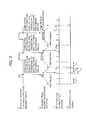
- Fig. 2 is a timing chart of typical operations.
- a symbol (a) shown in Fig. 2 indicates a beam utilization system extraction request signal that is generated from the beam utilization system control device 400 and used to request a charged particle beam that satisfies conditions necessary for the beam utilization system 500.
- a symbol (b) shown in Fig. 2 indicates an excitation pattern of the bending magnet 201 as a representative example of a magnet excitation pattern that is an operational pattern of the synchrotron 200.
- the excitation pattern includes an injection process, an acceleration process, an extraction process and a deceleration process.
- the synchrotron 200 operates in an operation cycle that includes time periods for the processes.
- Fig. 3 shows details of the magnet excitation pattern of the synchrotron.
- an injection timing is the time when the charged particle beam accelerated by the linear accelerator 111 is injected into the synchrotron 200.
- the magnet excitation pattern is synchronized with control of corresponding radio frequency acceleration and radio frequency deceleration for a time period from the injection timing through the injection process and the acceleration process to the start of the extraction process and for a time period from the completion of the extraction process through the deceleration process to the injection timing of the next operation cycle of the synchrotron 200.
- the injection timing, operational patterns in the injection process, the acceleration process and the deceleration process, and time periods for the injection process, the acceleration process and the deceleration process are determined before the magnet excitation pattern is created.
- a radio frequency operation of the linear accelerator 111 is performed in cycles (operation cycles indicated by T cyc ) indicated by a symbol (c) shown in Fig. 2 .
- radio frequency operation of beam injection device means a radio frequency operation cycle of the linear accelerator 111.
- the "radio frequency operation of the beam injection device” also indicates the same meaning.
- the injection timing of the synchrotron 200 matches the time (operation timing of the linear accelerator 111) when the beam can be supplied from the linear accelerator 111, and the beam can be injected without a problem.
- the time period for which the extraction request signal is transmitted from the beam utilization system 500 is not constant as indicated by the symbol (a) of Fig.
- the injection timing does not match the operation cycle of the beam injection device and the synchrotron 200 waits for the injection of the beam for a certain time (waiting time). For an operation of the synchrotron 200, it is necessary to match the injection timing with the operation cycle of the beam injection device.
- an injection pretrigger signal is generated at a specific time after completion of the extraction process so as to notify the injection system 100 of timing of injection of the beam in the next operation cycle of the synchrotron 200. Then, the timing of the radio frequency operation of the linear accelerator 111 is changed on the basis of the injection pretrigger signal so that the operation cycle of the beam injection device temporarily increases and the injection timing of the synchrotron 200 matches the time (operation timing of the linear accelerator 111) when the beam can be supplied from the linear accelerator 111.
- a symbol (d) shown in Fig. 2 indicates timings of injections of the beam.
- the generation timing of the injection pretrigger signal is set in a time period (shown in Fig. 3 ) that ranges from the time of completion of the extraction process to the time of termination of the deceleration process and is included in a time period ranging from the time of the completion of the extraction process to the injection timing of the next operation cycle of the synchrotron 200.
- a time period that ranges from the time when the injection pretrigger signal is generated during the operation of the synchrotron 200 to the injection timing of the next operation cycle of the synchrotron 200 is indicated by T pre as shown in Fig. 2 .
- the generation timing of the injection pretrigger signal is set to the time that is earlier by the time period T pre than the injection timing (known timing) of the next operation cycle of the synchrotron 200.
- a new cycle of the radio frequency operation of the beam injection device starts on the basis of the generation time of the injection pretrigger signal.
- a radio frequency operation timing signal is generated for the linear accelerator 111 when the operation cycle T cyc of the linear accelerator 111 elapses after the generation time of the injection pretrigger signal.
- an actual operation cycle (indicated by T' cyc ) of the linear accelerator 111 temporarily increases and matches the injection timing of the synchrotron 200 without a reduction in the operation cycle of the beam injection device, and the beam can be supplied from the linear accelerator 111.
- the increased operation cycle T' cyc does not exceed the double of the original basic cycle T cyc , or T' cyc ⁇ 2 ⁇ T cyc .
- the increased operation cycle T' cyc is not significantly changed from the basic cycle, and a stable operation can be performed.
- the accelerator control device 210 forms a first control device that controls the beam extraction devices 203 and 205 of the synchrotron 200 in the process for causing the charged particle beam to be extracted from the synchrotron 200 in the operation cycle of the synchrotron 200 so that the charged particle beam is extracted only for a time period requested by the beam utilization system 500 (irradiation device).
- the accelerator control device 210 forms a second control device that changes the operation timing of the linear accelerator 111 after the process for extracting the charged particle beam from the synchrotron 200 is completed by the control of the beam extraction devices 203 and 205 in the operation cycle of the synchrotron 200 so that the operation cycle of the linear accelerator 111 temporarily increases, the second control device allowing the operation timing of the linear accelerator 111 to match the injection timing of the next operation cycle of the synchrotron 200.
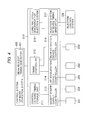
- the accelerator control device 210 includes a control pattern/timing storage unit 211.
- the control pattern/timing storage unit 211 stores the magnet excitation pattern (shown in Fig. 3 ) of the synchrotron 200 and various control parameters such as an acceleration timing associated with the magnet excitation pattern, an extraction preparation timing associated with the magnet excitation pattern, a deceleration timing associated with the magnet excitation pattern, the generation timing of the injection pretrigger signal.
- the control pattern/timing storage unit 211 stores the time period T pre so that the time period T pre is associated with the injection timing of the operation cycle of the synchrotron 200 and that the generation timing of the injection pretrigger signal is the time earlier by the time period T pre than the injection timing of the operation cycle of the synchrotron 200.
- the control pattern/timing storage unit 211 is connected to a magnet power supply controller 213 and controls the bending magnet 201, the beam injection device 204 and the beam extraction device 205, which are included in the synchrotron 200.
- the timings that are stored in the control pattern/timing storage unit 211 are used to control other devices through a timing controller 212.
- the timing controller 212 controls the RF acceleration cavity 202 through an RF acceleration cavity controller 214 and controls the beam extraction device 203 through a beam extraction device controller 215.
- the timing controller 212 receives the extraction request signal, the next pattern transition signal or the energy switch request signal from a beam request timing generator 401 that is included in the beam utilization system control device 400.
- the timing controller 212 controls the beam extraction device 203 through the beam extraction device controller 215 so that the beam extraction device 203 causes the beam to be extracted from the synchrotron 200.
- the basic cycle (constant cycle) T cyc of the radio frequency device operation of the linear accelerator 111 is generated by a beam injection device-dedicated constant cycle generator 216.
- a beam injection device-dedicated radio frequency device timing generator 217 generates a radio frequency device operation timing of the linear accelerator 111.
- the beam injection device-dedicated radio frequency device timing generator 217 adjusts the constant basic cycle generated by the beam injection device-dedicated constant cycle generator 216 in accordance with the injection pretrigger signal generated by the timing controller 212 and supplies, as a radio frequency device operation timing, the adjusted cycle to the injection control system 120.
- the injection control system 120 repeatedly activates the RF power supply 112 (shown in Fig. 1 ) and the power supply 102 for the ion source (shown in Fig. 1 ) while synchronizing the RF power supply 112 and the power supply 102 for the ion source with the radio frequency device operation timing as indicated by the symbol (c) shown in Fig. 2 . It is not necessary to accelerate the beam in all cycles of the radio frequency operation. Thus, for example, the beam is set by the method described in Non-Patent Document 3 so as not to be accelerated and is accelerated only at the injection timings as indicated by the symbol (d) shown in Fig. 2 .
- the radio frequency operation of the linear accelerator 111 is performed at the timings indicated by the symbol (c) shown in Fig. 2 .
- the timings indicated by the symbol (c) shown in Fig. 2 at a timing that does not match any of the injection timings indicated by the symbol (d) shown in Fig. 2 , the charged particles that are generated by the ion source 101 are not accelerated, and the linear accelerator 111 operates while not accelerating the charged particles.
- the charged particles that are generated by the ion source 101 are accelerated and injected into the synchrotron 200.
- the beam injection device-dedicated constant cycle generator 216 and the beam injection device-dedicated radio frequency device timing generator 217 form a part of the accelerator control device 210.
- at least one of the beam injection device-dedicated constant cycle generator 216 and the beam injection device-dedicated radio frequency device timing generator 217 may form a part of the accelerator control device 210. In this case, the aforementioned operations can be achieved.
- an allowable set range of the time period T pre may vary due to a process of controlling the energy of the beam to be accelerated in the synchrotron 200 and extracted from the synchrotron 200.
- the time period T pre may not be equal to the operation cycle T cyc of the linear accelerator 111.
- the energy of the beam at the time of the extraction may vary as shown in Fig. 5 .
- an excitation level of the magnet excitation pattern may vary as indicated by levels (a), (b) and (c) shown in Fig. 5 .
- the time period for the deceleration process may vary depending on the energy of the beam.
- the generation timing of the injection pretrigger signal may vary as indicated by injection pretriggers (a), (b) and (c). Therefore, the time period T pre that ranges from the generation time of the injection pretrigger signal to the injection time of the beam may vary as indicated by time periods T pre (a), T pre (b) and T pre (c).
- the operation cycle T cyc and the time period T pre are not equal to each other in some cases.
- T cyc T pre
- T cyc ⁇ N N is an integer
- a new radio frequency of the beam injection device is generated when the operation cycle T cyc elapses after the generation of the injection pretrigger signal. After that, the constant operation cycle T cyc starts. In this manner, the injection timing of the synchrotron 200 can match the time when the linear accelerator 111 can supply the beam.
- the radio frequency operation timing is generated when the time period T res elapses after the generation of the injection pretrigger signal (refer to Fig. 7 ).
- the radio frequency operation timing is generated when a time period of T res + T cyc elapses after the generation of the injection pretrigger signal (refer to Fig. 8 ).
- a new radio frequency of the beam injection device is generated. After that, the constant operation cycle T cyc starts. In this manner, the injection timing of the synchrotron 200 can match the time when the linear accelerator 111 can supply the beam.
- the radio frequency operation timing is generated when the time period T pre elapses after the generation of the injection pretrigger signal (refer to Fig. 9 ).
- the timings be set so that the operation cycle T cyc of the linear accelerator 200 is shorter than the time period T pre that ranges from the generation time of the injection pretrigger signal to the injection time of the beam to prevent the operations shown in Figs. 9 and 10 .
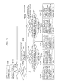
- Fig. 11 is a flowchart of a process of determining a relationship between the operation cycle T cyc of the linear accelerator 111 and the time period T pre ranging from the generation time of the injection pretrigger signal to the injection time of the beam, the relationships being shown in Figs. 2 , 6 to 10 .
- the process of determining the relationship is described with reference to Fig. 4 showing the configuration of the control device 210.
- Conditions for irradiation with the charged particle beam to be utilized by the beam utilization system 500 are set by the beam utilization system control device 400 (in step S100).
- a corresponding pattern is selected from the data stored in the control pattern/timing storage unit 211 included in the accelerator control device 210 (in step S110).
- the operation cycle T cyc is known as a characteristic value of the linear accelerator 111.
- the timing controller 212 can detect the relationship between T cyc and T pre .
- the timing controller 212 determines whether or not the time period T pre is equal to or larger than the operation cycle T cyc (in step S120).
- the beam injection device-dedicated radio frequency device timing generator 217 generates the radio frequency operation timing of the linear accelerator 111 when the operation cycle T cyc elapses after the generation of the injection pretrigger signal, and the beam injection device-dedicated radio frequency device timing generator 217 causes the beam injection device radio frequency device to operate (in step S140).
- the beam injection device-dedicated radio frequency device timing generator 217 determines, on the basis of the relationship between the generation time of the injection pretrigger signal and the basic cycle (constant cycle) generated by the beam injection device-dedicated constant cycle generator 216, whether or not the sum of the time period T res and the time that elapses after the radio frequency operation timing immediately before the generation of the injection pretrigger signal is larger than the operation cycle T cyc for each of operation cycles of the synchrotron 200 (in step S160).
- the beam injection device-dedicated radio frequency device timing generator 217 generates the radio frequency operation timing of the linear accelerator 111 on the basis of the result of the determination and causes the beam injection device radio frequency device to operate (in step S170 or S180).
- the determination method is not limited to the aforementioned method. Another determination method may be performed as long as the relationships among the magnet excitation pattern (b) of the synchrotron, the radio frequency operation (c) of the beam injection device and the beam injection timing (d), which are shown in any of Figs. 6 to 10 , are established.
- the pretrigger timing (injection pretrigger signal) that is used to notify the linear accelerator 111 of the requested injection timing after the completion of the extraction process is set for timing control that is used to control the injection process, the acceleration process, the extraction process and the deceleration process in the synchrotron 200.
- the operation timing of the linear accelerator 111 is changed so that the operation cycle of the linear accelerator 111 temporarily increases.
- the charged particle beam can be injected into the synchrotron 200 at an arbitrary timing while a lower limit of the operation cycle of the linear accelerator 111 is maintained.
- the synchrotron 200 can receives the charged particle beam injected from the linear accelerator 111 at the injection timing requested by the synchrotron 200.
- the synchrotron 200 can receives the charged particle beam injected from the linear accelerator 111 at the injection timing requested by the synchrotron 200, it is possible to reduce the time for irradiation of a tumor and thereby reduce the time for therapy, and the system can efficiently operate in the irradiation device utilizing the charged particle beam accelerated by the synchrotron 200.
- the charged particle beam irradiation system according to the second embodiment includes an irradiation device 600 that irradiates a tumor (such as cancer) of a patient with a charged particle beam (ion beam) such as protons or carbon ions, and thereby performs a therapy.
- the irradiation device 600 is provided as the beam utilization system 500 according to the first embodiment.
- the charged particle beam is transported from the synchrotron 200 through the beam transport system 300 to the irradiation device 600.
- the irradiation device 600 is described with reference to Fig. 13 .
- the irradiation device 600 has an X-direction scanning magnet 601A and a Y-direction scanning magnet 601B that scan a tumor 611 of a patient 610 with the charged particle beam (guided by the beam transport system 300) in a horizontal direction (X direction shown in Fig. 13 ) and a vertical direction (direction (Y direction) perpendicular to the sheet of Fig. 13 ).
- the charged particle beam that is deflected by the X-direction scanning magnet 601A and the Y-direction scanning magnet 601B passes through a beam position monitor 602 and a dose monitor 603 so that the tumor 611 is irradiated with the charged particle beam.
- the beam position monitor 602 measures the position and width (spreading) of the charged particle beam.
- the dose monitor 603 measures an irradiation dose of the charged particle beam.
- Fig. 14 is a diagram showing the tumor 611 when viewed from the upstream side of the charged particle beam.
- the tumor 611 of the patient 610 is three-dimensionally divided into a plurality of layers in a depth direction (Z direction in Fig. 13 ).
- the layers are each two-dimensionally divided into a plurality of spots 612 (hereinafter referred to as irradiation spots).
- the depth direction corresponds to a depth that the charged particle beam reaches.
- the depth that the charged particle beam reaches is changed by changing the energy of the charged particle beam to be extracted from the synchrotron 200 so that the layers can be selectively irradiated.
- the scanning magnets 601A and 601B deflects the charged particle beam so as to two-dimensionally scan each of the layers with the charged particle beam along an irradiation path 613 so that a predetermined dose is provided to each of the irradiation spots as shown in Fig. 14 , for example.
- the dose of the charged particle beam with which each of the irradiation spots is irradiated is measured by the dose monitor 603.
- the position and spreading of the charged particle beam are measured by the beam position monitor 602.
- a request for a transition to the next pattern is provided to the synchrotron 200.
- the extraction of the beam from the synchrotron 200 during the operation cycle may be stopped, and the timing of the transition to the next pattern may not be constant.
- the depth that the charged particle beam reaches in the depth direction (Z direction) needs to be changed.
- the energy of the beam extracted from the synchrotron 200 is changed.
- the timing of completion of the extraction in the operation cycle of the synchrotron 200 may not be constant.
- the operation cycle of the synchrotron 200 and the timing of the extraction from the synchrotron 200 are not constant when the irradiation device 600 is used in the present embodiment.
- the cycle of the radio frequency operation of the linear accelerator 111 is fixed, the charged particle beam may not be injected into the synchrotron 200 at an injection timing desired for the synchrotron 200, and the irradiation time period may be increased.
- the accelerator control device 210 (first control device) generates and outputs the next pattern transition request signal that indicates a request for a transition of the operational pattern of the synchrotron 200.
- the irradiation of all the spots shown in Fig.
- the irradiation control device 620 (first control device) outputs the energy switch request signal that indicates a request for a change in the energy of the beam extracted from the synchrotron 200.
- the accelerator control device 210 (control device, second control device) performs the operation method (shown in Fig. 2 ) according to the present invention when the accelerator control device 210 generates the next pattern transition request signal or when the accelerator control device 210 receives the energy switch request signal, and changes the operation timing of the linear accelerator 111 on the basis of the pretrigger timing (injection pretrigger signal) so that the operation cycle of the linear accelerator 111 temporarily increases.
- the injection timing can be set to a desired timing. Therefore, the irradiation time period is not increased, the time for the therapy can be reduced.
- the system can efficiently operate.
- a target to be irradiated is a cube that has sides of 10 cm and a volume of 1 litter; the number of irradiation spots that are necessary to irradiate the cube is 10,000; the number of layers (of the target) divided in the depth direction (Z direction) is 30; and it is necessary that the total of the number of changes of the operation cycle of the synchrotron 200 and the number of changes of the energy be 40 during irradiation.
- the reason that the number of the divided layers does not match the total of the number of changes of the operation cycle of the synchrotron 200 and the number of changes of the energy is that when the amount of charged particles with which each of the layers is irradiated is large, the amount of charged particles that can be extracted for one operation cycle of the synchrotron 200 is not sufficient and each of the layers is irradiated for a plurality of operation cycles of the synchrotron 200.
- T cyc of the beam injection device is set to 0.5 seconds and the present invention is applied, a waiting time does not occur immediately before the cycle.
- the radio frequency operation cycle T cyc of the beam injection device is set to 0.5 seconds and the present invention is not applied, a waiting time of up to 0.5 seconds occurs immediately before the cycle. However, the waiting time may not occur by accident.
- a waiting time of 0.25 seconds which is an intermediate value, is set to occur immediately before each radio frequency operation cycle of the beam injection device, and the operation cycle is changed 40 times, the irradiation time is increased by 10 seconds.
- the irradiation time in the case where the present invention is not applied is set to, for example, approximately 100 seconds, the irradiation time is reduced by 10 seconds that correspond to a 10% reduction.
- the charged particle beam irradiation system according to the third embodiment includes an irradiation device 700 that irradiates a tumor (such as cancer) of a patient with a charged particle beam (ion beam) such as protons or carbon ions, and thereby performs a therapy.
- the irradiation device 700 is provided as the beam utilization system 500 according to the first embodiment.
- the irradiation system includes a unit that detects a movement (caused by breathing of the patient) of the tumor and movements of others.
- charged particles are transported from the synchrotron 200 through the beam transport system 300 to the irradiation device 700.
- the irradiation device 700 is described with reference to Fig. 13 .
- a method for forming an irradiation field by the irradiation device 700 may be any method for forming an irradiation field, such as a scatterer method using scattering of a charged particle beam or the aforementioned scanning method.
- a detecting unit 710 is provided to detect a movement of the tumor 611 of the patient 610. In order to achieve an irradiation of the tumor with high accuracy, a method for detecting a movement of the tumor and irradiating the tumor only when the movement is in a predetermined range has been proposed.
- a method for monitoring a movement of a body surface to detect a respiratory movement a method for monitoring respiratory air flow caused by respiration and inspired air flow in the vicinity of the mouth of the patient, and a method for directly monitoring the position of the tumor or a marker of the tumor using an X ray transparent image or the like may be used.
- Figs. 16(a) and 16(b) are diagrams showing the relationship between detection of a movement of the tumor and irradiation with the beam.
- Fig. 16(a) shows a detected signal indicating movements of the tumor and a threshold range of the signal.
- the tumor is located at a desired position or located in a desired range including the desired position. Only when the value of the detected signal (tumor position detection signal) is in the threshold range, the tumor is irradiated with the beam.
- times when the irradiation device 700 according to the present embodiment can irradiate the tumor are shown in Fig. 16(b) . Since the signal indicates the movements of the patient, the times may not be constant.
- the operation cycle of the synchrotron 200 and the timing of the extraction are not constant.
- the cycle of the radio frequency operation of the linear accelerator 111 is fixed, the charged particle beam cannot be injected into the synchrotron 200 at the injection timing desired for the synchrotron 200.
- the irradiation time period may be increased.
- the irradiation control device 720 sets a timing of a time period for which the target to be irradiated can be irradiated on the basis of the signal obtained by the detection of the movements of the target to be irradiated as shown in Fig. 16(b) .
- the irradiation control device 720 (first control device) outputs a beam extraction request signal to request the extraction of the beam only for the time period for which the target to be irradiated can be irradiated on the basis of the signal.
- the accelerator control device 210 receives the signal, performs the operation method (shown in Fig.
- the injection timing can be set to a desired timing. Therefore, the irradiation time period is not increased, the time for the therapy can be reduced, and the system can efficiently operate.
Landscapes
- Physics & Mathematics (AREA)
- Engineering & Computer Science (AREA)
- Spectroscopy & Molecular Physics (AREA)
- Plasma & Fusion (AREA)
- General Engineering & Computer Science (AREA)
- High Energy & Nuclear Physics (AREA)
- Particle Accelerators (AREA)
- Radiation-Therapy Devices (AREA)
Applications Claiming Priority (1)
| Application Number | Priority Date | Filing Date | Title |
|---|---|---|---|
| JP2010105522A JP5456562B2 (ja) | 2010-04-30 | 2010-04-30 | 荷電粒子ビーム発生装置、荷電粒子ビーム照射装置及びそれらの運転方法 |
Publications (3)
| Publication Number | Publication Date |
|---|---|
| EP2384099A2 true EP2384099A2 (de) | 2011-11-02 |
| EP2384099A3 EP2384099A3 (de) | 2014-04-16 |
| EP2384099B1 EP2384099B1 (de) | 2016-09-07 |
Family
ID=44315146
Family Applications (1)
| Application Number | Title | Priority Date | Filing Date |
|---|---|---|---|
| EP11164182.5A Active EP2384099B1 (de) | 2010-04-30 | 2011-04-28 | Geladene Teilchen-Strahlgenerator und System zur Bestrahlung geladenen Teilchen |
Country Status (3)
| Country | Link |
|---|---|
| US (1) | US8742699B2 (de) |
| EP (1) | EP2384099B1 (de) |
| JP (1) | JP5456562B2 (de) |
Cited By (6)
| Publication number | Priority date | Publication date | Assignee | Title |
|---|---|---|---|---|
| EP2687262A1 (de) * | 2012-07-19 | 2014-01-22 | Hitachi Ltd. | Teilchenstrahlbestrahlungssystem |
| EP2829302A1 (de) * | 2013-07-26 | 2015-01-28 | Hitachi Ltd. | Teilchenstrahlbestrahlungssystem und Verfahren zum Betrieb davon |
| EP2842603A1 (de) * | 2013-08-30 | 2015-03-04 | Hitachi Ltd. | Teilchenstrahlbestrahlungssystem und Betriebsverfahren |
| CN105027686A (zh) * | 2013-02-28 | 2015-11-04 | 三菱电机株式会社 | 高频加速器的制造方法、高频加速器以及圆形加速器系统 |
| EP2832399A4 (de) * | 2012-03-27 | 2015-11-25 | Mitsubishi Electric Corp | Teilchenstrahltherapievorrichtung und betriebsverfahren für die teilchenstrahltherapievorrichtung |
| EP3116290A4 (de) * | 2014-03-07 | 2017-09-20 | Hitachi, Ltd. | Ladungsträgerstrahlstrahlungssystem, synchrotron und strahlausstossverfahren dafür |
Families Citing this family (16)
| Publication number | Priority date | Publication date | Assignee | Title |
|---|---|---|---|---|
| JP2014022222A (ja) * | 2012-07-19 | 2014-02-03 | Hitachi Ltd | 粒子線照射システムとその運転方法 |
| JP5963308B2 (ja) * | 2012-12-03 | 2016-08-03 | 株式会社日立製作所 | 粒子線照射システム及び運転制御パターンデータの生成方法 |
| JP5978125B2 (ja) * | 2012-12-27 | 2016-08-24 | 株式会社日立製作所 | 粒子線治療システム |
| JP5998089B2 (ja) * | 2013-03-25 | 2016-09-28 | 株式会社日立製作所 | 粒子線照射システムとその運転方法 |
| KR20150024650A (ko) * | 2013-08-27 | 2015-03-09 | 삼성전자주식회사 | 전자 장치에서 사운드를 시각적으로 제공하기 위한 방법 및 장치 |
| EP3049151B1 (de) | 2013-09-27 | 2019-12-25 | Mevion Medical Systems, Inc. | Teilchenstrahlabtastung |
| US9661736B2 (en) * | 2014-02-20 | 2017-05-23 | Mevion Medical Systems, Inc. | Scanning system for a particle therapy system |
| JP6200368B2 (ja) * | 2014-04-07 | 2017-09-20 | 株式会社日立製作所 | 荷電粒子照射システムおよび荷電粒子ビーム照射システムの制御方法 |
| JP6316173B2 (ja) * | 2014-11-21 | 2018-04-25 | 株式会社日立製作所 | 荷電粒子ビーム発生装置、荷電粒子ビーム照射装置、粒子線治療システムおよび荷電粒子ビーム発生装置の運転方法 |
| EP3232742B1 (de) * | 2014-12-08 | 2020-11-18 | Hitachi, Ltd. | Beschleuniger und teilchenstrahlstrahlenvorrichtung |
| JP6523929B2 (ja) * | 2015-11-19 | 2019-06-05 | 株式会社東芝 | 粒子線加速システム、粒子線加速制御方法、及び粒子線治療装置 |
| CN105536154B (zh) * | 2015-12-16 | 2018-03-23 | 中国科学院上海应用物理研究所 | 一种基于硬件控制的辐照扫描装置及辐照扫描方法 |
| JP6279036B2 (ja) * | 2016-08-29 | 2018-02-14 | 株式会社日立製作所 | 粒子線照射システムとその運転方法 |
| EP3934751B1 (de) | 2019-03-08 | 2024-07-17 | Mevion Medical Systems, Inc. | Kollimator und energieabbau für ein teilchentherapiesystem |
| JP7290274B2 (ja) * | 2019-07-04 | 2023-06-13 | 東芝エネルギーシステムズ株式会社 | 荷電粒子の出射制御装置、方法及びプログラム |
| CN117393409B (zh) * | 2023-11-27 | 2024-04-05 | 青岛四方思锐智能技术有限公司 | 一种周期脉冲高能离子注入机 |
Citations (2)
| Publication number | Priority date | Publication date | Assignee | Title |
|---|---|---|---|---|
| JP2833602B2 (ja) | 1995-12-11 | 1998-12-09 | 株式会社日立製作所 | 荷電粒子出射方法および荷電粒子出射装置 |
| JP3518270B2 (ja) | 1996-08-30 | 2004-04-12 | 株式会社日立製作所 | 荷電粒子ビーム装置 |
Family Cites Families (10)
| Publication number | Priority date | Publication date | Assignee | Title |
|---|---|---|---|---|
| EP0779081A3 (de) | 1995-12-11 | 1999-02-03 | Hitachi, Ltd. | Strahlapparat für geladene Teilchen und Betriebsverfahren dafür |
| EP1378266A1 (de) | 1996-08-30 | 2004-01-07 | Hitachi, Ltd. | Vorrichtung zum Bestrahlen mit geladenen Teilchen |
| JP3899781B2 (ja) | 2000-05-16 | 2007-03-28 | 三菱電機株式会社 | 直線加速装置、シンクロトロン加速装置、粒子線治療装置および加速装置の制御方法 |
| DE10205949B4 (de) | 2002-02-12 | 2013-04-25 | Gsi Helmholtzzentrum Für Schwerionenforschung Gmbh | Verfahren und Vorrichtung zum Steuern einer nach dem Rasterscanverfahren arbeitenden Bestrahlungseinrichtung für schwere Ionen oder Protonen mit Strahlextraktion |
| US6822244B2 (en) | 2003-01-02 | 2004-11-23 | Loma Linda University Medical Center | Configuration management and retrieval system for proton beam therapy system |
| ITCO20050028A1 (it) * | 2005-11-11 | 2007-05-12 | Fond Per Adroterapia Oncologica | Complesso di acceleratori di protoni in particolare per uso medicale |
| JP4179372B2 (ja) * | 2006-11-02 | 2008-11-12 | 三菱電機株式会社 | 直線加速装置、シンクロトロン加速装置、粒子線治療装置および加速装置の制御方法 |
| JP4378396B2 (ja) * | 2007-06-22 | 2009-12-02 | 株式会社日立製作所 | 粒子線照射システム |
| JP4988516B2 (ja) | 2007-11-06 | 2012-08-01 | 株式会社日立製作所 | 粒子線治療システム |
| JP4691574B2 (ja) * | 2008-05-14 | 2011-06-01 | 株式会社日立製作所 | 荷電粒子ビーム出射装置及び荷電粒子ビーム出射方法 |
-
2010
- 2010-04-30 JP JP2010105522A patent/JP5456562B2/ja active Active
-
2011
- 2011-04-27 US US13/095,470 patent/US8742699B2/en active Active
- 2011-04-28 EP EP11164182.5A patent/EP2384099B1/de active Active
Patent Citations (2)
| Publication number | Priority date | Publication date | Assignee | Title |
|---|---|---|---|---|
| JP2833602B2 (ja) | 1995-12-11 | 1998-12-09 | 株式会社日立製作所 | 荷電粒子出射方法および荷電粒子出射装置 |
| JP3518270B2 (ja) | 1996-08-30 | 2004-04-12 | 株式会社日立製作所 | 荷電粒子ビーム装置 |
Non-Patent Citations (3)
| Title |
|---|
| AKIRA TAKAGI: "OHO' 96 High Energy Accelerator Seminar", HIGH-INTENSITY PROTON ACCELERATOR OF HADRON PROJECT, 1996, pages I-17 |
| KENJI SAWADA ET AL.: "Design, Manufacture, and Performance Test of the Injector for Hyogo Hadrontherapy Center", PROC. OF THE 12TH SYMPOSIUM ON ACCELERATOR SCIENCE AND TECHNOLOGY, 1999 |
| M. MAIER: "Commissioning of the Linac for the Heidelberg Heavy Ion Center Therapy Center (HIT)", PROC. OF PARTICLE ACCELERATOR CONFERENCE, 2007, pages 2734 |
Cited By (12)
| Publication number | Priority date | Publication date | Assignee | Title |
|---|---|---|---|---|
| EP2832399A4 (de) * | 2012-03-27 | 2015-11-25 | Mitsubishi Electric Corp | Teilchenstrahltherapievorrichtung und betriebsverfahren für die teilchenstrahltherapievorrichtung |
| EP2687262A1 (de) * | 2012-07-19 | 2014-01-22 | Hitachi Ltd. | Teilchenstrahlbestrahlungssystem |
| CN103566488A (zh) * | 2012-07-19 | 2014-02-12 | 株式会社日立制作所 | 粒子线照射系统及其运转方法 |
| US9308394B2 (en) | 2012-07-19 | 2016-04-12 | Hitachi, Ltd. | Particle beam irradiation system and operating method |
| CN103566488B (zh) * | 2012-07-19 | 2017-04-12 | 株式会社日立制作所 | 粒子线照射系统 |
| CN105027686A (zh) * | 2013-02-28 | 2015-11-04 | 三菱电机株式会社 | 高频加速器的制造方法、高频加速器以及圆形加速器系统 |
| US20160014877A1 (en) * | 2013-02-28 | 2016-01-14 | Mitsubishi Electric Corporation | Method of manufacturing radio frequency accelerator, radio frequency accelerator, and circular accelerator system |
| US9402298B2 (en) * | 2013-02-28 | 2016-07-26 | Mitsubishi Electric Corporation | Method of manufacturing radio frequency accelerator, radio frequency accelerator, and circular accelerator system |
| EP2829302A1 (de) * | 2013-07-26 | 2015-01-28 | Hitachi Ltd. | Teilchenstrahlbestrahlungssystem und Verfahren zum Betrieb davon |
| EP2842603A1 (de) * | 2013-08-30 | 2015-03-04 | Hitachi Ltd. | Teilchenstrahlbestrahlungssystem und Betriebsverfahren |
| US9199095B2 (en) | 2013-08-30 | 2015-12-01 | Hitachi, Ltd. | Particle beam irradiation system and operating method |
| EP3116290A4 (de) * | 2014-03-07 | 2017-09-20 | Hitachi, Ltd. | Ladungsträgerstrahlstrahlungssystem, synchrotron und strahlausstossverfahren dafür |
Also Published As
| Publication number | Publication date |
|---|---|
| JP2011233478A (ja) | 2011-11-17 |
| US20110266981A1 (en) | 2011-11-03 |
| US8742699B2 (en) | 2014-06-03 |
| EP2384099B1 (de) | 2016-09-07 |
| JP5456562B2 (ja) | 2014-04-02 |
| EP2384099A3 (de) | 2014-04-16 |
Similar Documents
| Publication | Publication Date | Title |
|---|---|---|
| EP2384099B1 (de) | Geladene Teilchen-Strahlgenerator und System zur Bestrahlung geladenen Teilchen | |
| JP5002612B2 (ja) | 荷電粒子ビーム照射装置 | |
| US8466441B2 (en) | Particle beam therapy system | |
| US7122978B2 (en) | Charged-particle beam accelerator, particle beam radiation therapy system using the charged-particle beam accelerator, and method of operating the particle beam radiation therapy system | |
| US6580084B1 (en) | Accelerator system | |
| EP2305351B1 (de) | System zur Bestrahlung mit geladenen Teilchen | |
| US10143436B2 (en) | Particle therapy system | |
| CN103402581B (zh) | 粒子射线照射系统 | |
| CN104010694B (zh) | 粒子射线治疗装置及粒子射线治疗装置的运转方法 | |
| CN108837333A (zh) | 加速器控制装置、加速器控制方法以及粒子线治疗装置 | |
| CN108348767B (zh) | 粒子束治疗系统 | |
| US9596746B2 (en) | Charged particle beam generator, charged particle irradiation system, method for operating charged particle beam generator and method for operating charged particle irradiation system | |
| EP0779081A2 (de) | Strahlapparat für geladene Teilchen und Betriebsverfahren dafür | |
| CN111617391A (zh) | 粒子束治疗系统、粒子束治疗方法以及计算机程序 | |
| JP2011000378A (ja) | 荷電粒子ビーム照射システム | |
| US9937361B2 (en) | Particle beam irradiation apparatus | |
| US9694207B2 (en) | Control device for scanning electromagnet and particle beam therapy apapratus | |
| US20210031056A1 (en) | Charged particle beam treatment apparatus | |
| US8704197B2 (en) | Accelerator and method for irradiating a target volume | |
| CN109224317B (zh) | 带电粒子束治疗装置 | |
| CN106163615A (zh) | 粒子射线治疗装置 | |
| JP6815231B2 (ja) | 荷電粒子線治療装置 | |
| JP6553400B2 (ja) | 荷電粒子ビーム治療装置 | |
| JP2019141331A (ja) | 粒子線照射システムおよび照射計画装置 |
Legal Events
| Date | Code | Title | Description |
|---|---|---|---|
| 17P | Request for examination filed |
Effective date: 20110801 |
|
| AK | Designated contracting states |
Kind code of ref document: A2 Designated state(s): AL AT BE BG CH CY CZ DE DK EE ES FI FR GB GR HR HU IE IS IT LI LT LU LV MC MK MT NL NO PL PT RO RS SE SI SK SM TR |
|
| AX | Request for extension of the european patent |
Extension state: BA ME |
|
| PUAI | Public reference made under article 153(3) epc to a published international application that has entered the european phase |
Free format text: ORIGINAL CODE: 0009012 |
|
| PUAL | Search report despatched |
Free format text: ORIGINAL CODE: 0009013 |
|
| AK | Designated contracting states |
Kind code of ref document: A3 Designated state(s): AL AT BE BG CH CY CZ DE DK EE ES FI FR GB GR HR HU IE IS IT LI LT LU LV MC MK MT NL NO PL PT RO RS SE SI SK SM TR |
|
| AX | Request for extension of the european patent |
Extension state: BA ME |
|
| RIC1 | Information provided on ipc code assigned before grant |
Ipc: G21K 5/04 20060101ALI20140313BHEP Ipc: H05H 7/10 20060101AFI20140313BHEP Ipc: H05H 13/04 20060101ALI20140313BHEP Ipc: H05H 9/00 20060101ALI20140313BHEP |
|
| 17Q | First examination report despatched |
Effective date: 20150803 |
|
| REG | Reference to a national code |
Ref country code: DE Ref legal event code: R079 Ref document number: 602011030022 Country of ref document: DE Free format text: PREVIOUS MAIN CLASS: H05H0007100000 Ipc: G21K0001093000 |
|
| GRAP | Despatch of communication of intention to grant a patent |
Free format text: ORIGINAL CODE: EPIDOSNIGR1 |
|
| RIC1 | Information provided on ipc code assigned before grant |
Ipc: G21K 1/093 20060101AFI20160308BHEP Ipc: A61N 5/10 20060101ALI20160308BHEP |
|
| INTG | Intention to grant announced |
Effective date: 20160323 |
|
| GRAS | Grant fee paid |
Free format text: ORIGINAL CODE: EPIDOSNIGR3 |
|
| GRAA | (expected) grant |
Free format text: ORIGINAL CODE: 0009210 |
|
| AK | Designated contracting states |
Kind code of ref document: B1 Designated state(s): AL AT BE BG CH CY CZ DE DK EE ES FI FR GB GR HR HU IE IS IT LI LT LU LV MC MK MT NL NO PL PT RO RS SE SI SK SM TR |
|
| REG | Reference to a national code |
Ref country code: GB Ref legal event code: FG4D |
|
| REG | Reference to a national code |
Ref country code: CH Ref legal event code: EP |
|
| REG | Reference to a national code |
Ref country code: IE Ref legal event code: FG4D |
|
| REG | Reference to a national code |
Ref country code: AT Ref legal event code: REF Ref document number: 827499 Country of ref document: AT Kind code of ref document: T Effective date: 20161015 |
|
| REG | Reference to a national code |
Ref country code: DE Ref legal event code: R096 Ref document number: 602011030022 Country of ref document: DE |
|
| REG | Reference to a national code |
Ref country code: LT Ref legal event code: MG4D |
|
| REG | Reference to a national code |
Ref country code: NL Ref legal event code: MP Effective date: 20160907 |
|
| PG25 | Lapsed in a contracting state [announced via postgrant information from national office to epo] |
Ref country code: HR Free format text: LAPSE BECAUSE OF FAILURE TO SUBMIT A TRANSLATION OF THE DESCRIPTION OR TO PAY THE FEE WITHIN THE PRESCRIBED TIME-LIMIT Effective date: 20160907 Ref country code: FI Free format text: LAPSE BECAUSE OF FAILURE TO SUBMIT A TRANSLATION OF THE DESCRIPTION OR TO PAY THE FEE WITHIN THE PRESCRIBED TIME-LIMIT Effective date: 20160907 Ref country code: LT Free format text: LAPSE BECAUSE OF FAILURE TO SUBMIT A TRANSLATION OF THE DESCRIPTION OR TO PAY THE FEE WITHIN THE PRESCRIBED TIME-LIMIT Effective date: 20160907 Ref country code: NO Free format text: LAPSE BECAUSE OF FAILURE TO SUBMIT A TRANSLATION OF THE DESCRIPTION OR TO PAY THE FEE WITHIN THE PRESCRIBED TIME-LIMIT Effective date: 20161207 Ref country code: RS Free format text: LAPSE BECAUSE OF FAILURE TO SUBMIT A TRANSLATION OF THE DESCRIPTION OR TO PAY THE FEE WITHIN THE PRESCRIBED TIME-LIMIT Effective date: 20160907 |
|
| REG | Reference to a national code |
Ref country code: AT Ref legal event code: MK05 Ref document number: 827499 Country of ref document: AT Kind code of ref document: T Effective date: 20160907 |
|
| PG25 | Lapsed in a contracting state [announced via postgrant information from national office to epo] |
Ref country code: ES Free format text: LAPSE BECAUSE OF FAILURE TO SUBMIT A TRANSLATION OF THE DESCRIPTION OR TO PAY THE FEE WITHIN THE PRESCRIBED TIME-LIMIT Effective date: 20160907 Ref country code: LV Free format text: LAPSE BECAUSE OF FAILURE TO SUBMIT A TRANSLATION OF THE DESCRIPTION OR TO PAY THE FEE WITHIN THE PRESCRIBED TIME-LIMIT Effective date: 20160907 Ref country code: GR Free format text: LAPSE BECAUSE OF FAILURE TO SUBMIT A TRANSLATION OF THE DESCRIPTION OR TO PAY THE FEE WITHIN THE PRESCRIBED TIME-LIMIT Effective date: 20161208 Ref country code: SE Free format text: LAPSE BECAUSE OF FAILURE TO SUBMIT A TRANSLATION OF THE DESCRIPTION OR TO PAY THE FEE WITHIN THE PRESCRIBED TIME-LIMIT Effective date: 20160907 Ref country code: NL Free format text: LAPSE BECAUSE OF FAILURE TO SUBMIT A TRANSLATION OF THE DESCRIPTION OR TO PAY THE FEE WITHIN THE PRESCRIBED TIME-LIMIT Effective date: 20160907 |
|
| PG25 | Lapsed in a contracting state [announced via postgrant information from national office to epo] |
Ref country code: EE Free format text: LAPSE BECAUSE OF FAILURE TO SUBMIT A TRANSLATION OF THE DESCRIPTION OR TO PAY THE FEE WITHIN THE PRESCRIBED TIME-LIMIT Effective date: 20160907 Ref country code: RO Free format text: LAPSE BECAUSE OF FAILURE TO SUBMIT A TRANSLATION OF THE DESCRIPTION OR TO PAY THE FEE WITHIN THE PRESCRIBED TIME-LIMIT Effective date: 20160907 |
|
| REG | Reference to a national code |
Ref country code: FR Ref legal event code: PLFP Year of fee payment: 7 |
|
| PG25 | Lapsed in a contracting state [announced via postgrant information from national office to epo] |
Ref country code: CZ Free format text: LAPSE BECAUSE OF FAILURE TO SUBMIT A TRANSLATION OF THE DESCRIPTION OR TO PAY THE FEE WITHIN THE PRESCRIBED TIME-LIMIT Effective date: 20160907 Ref country code: BG Free format text: LAPSE BECAUSE OF FAILURE TO SUBMIT A TRANSLATION OF THE DESCRIPTION OR TO PAY THE FEE WITHIN THE PRESCRIBED TIME-LIMIT Effective date: 20161207 Ref country code: IS Free format text: LAPSE BECAUSE OF FAILURE TO SUBMIT A TRANSLATION OF THE DESCRIPTION OR TO PAY THE FEE WITHIN THE PRESCRIBED TIME-LIMIT Effective date: 20170107 Ref country code: PL Free format text: LAPSE BECAUSE OF FAILURE TO SUBMIT A TRANSLATION OF THE DESCRIPTION OR TO PAY THE FEE WITHIN THE PRESCRIBED TIME-LIMIT Effective date: 20160907 Ref country code: SK Free format text: LAPSE BECAUSE OF FAILURE TO SUBMIT A TRANSLATION OF THE DESCRIPTION OR TO PAY THE FEE WITHIN THE PRESCRIBED TIME-LIMIT Effective date: 20160907 Ref country code: SM Free format text: LAPSE BECAUSE OF FAILURE TO SUBMIT A TRANSLATION OF THE DESCRIPTION OR TO PAY THE FEE WITHIN THE PRESCRIBED TIME-LIMIT Effective date: 20160907 Ref country code: PT Free format text: LAPSE BECAUSE OF FAILURE TO SUBMIT A TRANSLATION OF THE DESCRIPTION OR TO PAY THE FEE WITHIN THE PRESCRIBED TIME-LIMIT Effective date: 20170109 Ref country code: AT Free format text: LAPSE BECAUSE OF FAILURE TO SUBMIT A TRANSLATION OF THE DESCRIPTION OR TO PAY THE FEE WITHIN THE PRESCRIBED TIME-LIMIT Effective date: 20160907 Ref country code: BE Free format text: LAPSE BECAUSE OF FAILURE TO SUBMIT A TRANSLATION OF THE DESCRIPTION OR TO PAY THE FEE WITHIN THE PRESCRIBED TIME-LIMIT Effective date: 20160907 |
|
| REG | Reference to a national code |
Ref country code: DE Ref legal event code: R097 Ref document number: 602011030022 Country of ref document: DE |
|
| PG25 | Lapsed in a contracting state [announced via postgrant information from national office to epo] |
Ref country code: IT Free format text: LAPSE BECAUSE OF FAILURE TO SUBMIT A TRANSLATION OF THE DESCRIPTION OR TO PAY THE FEE WITHIN THE PRESCRIBED TIME-LIMIT Effective date: 20160907 |
|
| PLBE | No opposition filed within time limit |
Free format text: ORIGINAL CODE: 0009261 |
|
| STAA | Information on the status of an ep patent application or granted ep patent |
Free format text: STATUS: NO OPPOSITION FILED WITHIN TIME LIMIT |
|
| PG25 | Lapsed in a contracting state [announced via postgrant information from national office to epo] |
Ref country code: DK Free format text: LAPSE BECAUSE OF FAILURE TO SUBMIT A TRANSLATION OF THE DESCRIPTION OR TO PAY THE FEE WITHIN THE PRESCRIBED TIME-LIMIT Effective date: 20160907 |
|
| 26N | No opposition filed |
Effective date: 20170608 |
|
| PG25 | Lapsed in a contracting state [announced via postgrant information from national office to epo] |
Ref country code: SI Free format text: LAPSE BECAUSE OF FAILURE TO SUBMIT A TRANSLATION OF THE DESCRIPTION OR TO PAY THE FEE WITHIN THE PRESCRIBED TIME-LIMIT Effective date: 20160907 |
|
| REG | Reference to a national code |
Ref country code: CH Ref legal event code: PL |
|
| REG | Reference to a national code |
Ref country code: IE Ref legal event code: MM4A |
|
| PG25 | Lapsed in a contracting state [announced via postgrant information from national office to epo] |
Ref country code: MC Free format text: LAPSE BECAUSE OF FAILURE TO SUBMIT A TRANSLATION OF THE DESCRIPTION OR TO PAY THE FEE WITHIN THE PRESCRIBED TIME-LIMIT Effective date: 20160907 |
|
| PG25 | Lapsed in a contracting state [announced via postgrant information from national office to epo] |
Ref country code: LU Free format text: LAPSE BECAUSE OF NON-PAYMENT OF DUE FEES Effective date: 20170428 Ref country code: LI Free format text: LAPSE BECAUSE OF NON-PAYMENT OF DUE FEES Effective date: 20170430 Ref country code: CH Free format text: LAPSE BECAUSE OF NON-PAYMENT OF DUE FEES Effective date: 20170430 |
|
| REG | Reference to a national code |
Ref country code: FR Ref legal event code: PLFP Year of fee payment: 8 |
|
| PG25 | Lapsed in a contracting state [announced via postgrant information from national office to epo] |
Ref country code: IE Free format text: LAPSE BECAUSE OF NON-PAYMENT OF DUE FEES Effective date: 20170428 |
|
| PG25 | Lapsed in a contracting state [announced via postgrant information from national office to epo] |
Ref country code: MT Free format text: LAPSE BECAUSE OF NON-PAYMENT OF DUE FEES Effective date: 20170428 |
|
| PG25 | Lapsed in a contracting state [announced via postgrant information from national office to epo] |
Ref country code: AL Free format text: LAPSE BECAUSE OF FAILURE TO SUBMIT A TRANSLATION OF THE DESCRIPTION OR TO PAY THE FEE WITHIN THE PRESCRIBED TIME-LIMIT Effective date: 20160907 |
|
| PG25 | Lapsed in a contracting state [announced via postgrant information from national office to epo] |
Ref country code: HU Free format text: LAPSE BECAUSE OF FAILURE TO SUBMIT A TRANSLATION OF THE DESCRIPTION OR TO PAY THE FEE WITHIN THE PRESCRIBED TIME-LIMIT; INVALID AB INITIO Effective date: 20110428 |
|
| PG25 | Lapsed in a contracting state [announced via postgrant information from national office to epo] |
Ref country code: CY Free format text: LAPSE BECAUSE OF NON-PAYMENT OF DUE FEES Effective date: 20160907 |
|
| PG25 | Lapsed in a contracting state [announced via postgrant information from national office to epo] |
Ref country code: MK Free format text: LAPSE BECAUSE OF FAILURE TO SUBMIT A TRANSLATION OF THE DESCRIPTION OR TO PAY THE FEE WITHIN THE PRESCRIBED TIME-LIMIT Effective date: 20160907 |
|
| PG25 | Lapsed in a contracting state [announced via postgrant information from national office to epo] |
Ref country code: TR Free format text: LAPSE BECAUSE OF FAILURE TO SUBMIT A TRANSLATION OF THE DESCRIPTION OR TO PAY THE FEE WITHIN THE PRESCRIBED TIME-LIMIT Effective date: 20160907 |
|
| REG | Reference to a national code |
Ref country code: DE Ref legal event code: R081 Ref document number: 602011030022 Country of ref document: DE Owner name: HITACHI HIGH-TECH CORPORATION, JP Free format text: FORMER OWNER: HITACHI, LTD., TOKYO, JP |
|
| REG | Reference to a national code |
Ref country code: GB Ref legal event code: 732E Free format text: REGISTERED BETWEEN 20240711 AND 20240717 |
|
| PGFP | Annual fee paid to national office [announced via postgrant information from national office to epo] |
Ref country code: DE Payment date: 20250305 Year of fee payment: 15 |
|
| PGFP | Annual fee paid to national office [announced via postgrant information from national office to epo] |
Ref country code: GB Payment date: 20260319 Year of fee payment: 16 |
|
| PGFP | Annual fee paid to national office [announced via postgrant information from national office to epo] |
Ref country code: FR Payment date: 20260320 Year of fee payment: 16 |