EP2384642A2 - Dispositif destiné au traitement d'aliments - Google Patents
Dispositif destiné au traitement d'aliments Download PDFInfo
- Publication number
- EP2384642A2 EP2384642A2 EP11003100A EP11003100A EP2384642A2 EP 2384642 A2 EP2384642 A2 EP 2384642A2 EP 11003100 A EP11003100 A EP 11003100A EP 11003100 A EP11003100 A EP 11003100A EP 2384642 A2 EP2384642 A2 EP 2384642A2
- Authority
- EP
- European Patent Office
- Prior art keywords
- guide
- guide surface
- knife
- filling opening
- shaft
- Prior art date
- Legal status (The legal status is an assumption and is not a legal conclusion. Google has not performed a legal analysis and makes no representation as to the accuracy of the status listed.)
- Withdrawn
Links
- 235000013305 food Nutrition 0.000 title claims abstract description 29
- 238000005520 cutting process Methods 0.000 claims abstract description 49
- 235000013372 meat Nutrition 0.000 claims description 4
- 235000013580 sausages Nutrition 0.000 claims description 4
- 235000013351 cheese Nutrition 0.000 description 2
- 238000010276 construction Methods 0.000 description 1
- 230000001419 dependent effect Effects 0.000 description 1
- 238000011161 development Methods 0.000 description 1
- 230000018109 developmental process Effects 0.000 description 1
- 238000006073 displacement reaction Methods 0.000 description 1
- 238000005429 filling process Methods 0.000 description 1
- 238000000034 method Methods 0.000 description 1
- 238000003825 pressing Methods 0.000 description 1
- 238000000926 separation method Methods 0.000 description 1
Images




Classifications
-
- A—HUMAN NECESSITIES
- A22—BUTCHERING; MEAT TREATMENT; PROCESSING POULTRY OR FISH
- A22C—PROCESSING MEAT, POULTRY, OR FISH
- A22C17/00—Other devices for processing meat or bones
- A22C17/0006—Cutting or shaping meat
- A22C17/0033—Cutting slices out of a piece of meat
-
- A—HUMAN NECESSITIES
- A22—BUTCHERING; MEAT TREATMENT; PROCESSING POULTRY OR FISH
- A22C—PROCESSING MEAT, POULTRY, OR FISH
- A22C17/00—Other devices for processing meat or bones
- A22C17/0006—Cutting or shaping meat
- A22C17/002—Producing portions of meat with predetermined characteristics, e.g. weight or particular dimensions
-
- B—PERFORMING OPERATIONS; TRANSPORTING
- B26—HAND CUTTING TOOLS; CUTTING; SEVERING
- B26D—CUTTING; DETAILS COMMON TO MACHINES FOR PERFORATING, PUNCHING, CUTTING-OUT, STAMPING-OUT OR SEVERING
- B26D1/00—Cutting through work characterised by the nature or movement of the cutting member or particular materials not otherwise provided for; Apparatus or machines therefor; Cutting members therefor
- B26D1/01—Cutting through work characterised by the nature or movement of the cutting member or particular materials not otherwise provided for; Apparatus or machines therefor; Cutting members therefor involving a cutting member which does not travel with the work
- B26D1/04—Cutting through work characterised by the nature or movement of the cutting member or particular materials not otherwise provided for; Apparatus or machines therefor; Cutting members therefor involving a cutting member which does not travel with the work having a linearly-movable cutting member
- B26D1/06—Cutting through work characterised by the nature or movement of the cutting member or particular materials not otherwise provided for; Apparatus or machines therefor; Cutting members therefor involving a cutting member which does not travel with the work having a linearly-movable cutting member wherein the cutting member reciprocates
- B26D1/08—Cutting through work characterised by the nature or movement of the cutting member or particular materials not otherwise provided for; Apparatus or machines therefor; Cutting members therefor involving a cutting member which does not travel with the work having a linearly-movable cutting member wherein the cutting member reciprocates of the guillotine type
-
- B—PERFORMING OPERATIONS; TRANSPORTING
- B26—HAND CUTTING TOOLS; CUTTING; SEVERING
- B26D—CUTTING; DETAILS COMMON TO MACHINES FOR PERFORATING, PUNCHING, CUTTING-OUT, STAMPING-OUT OR SEVERING
- B26D1/00—Cutting through work characterised by the nature or movement of the cutting member or particular materials not otherwise provided for; Apparatus or machines therefor; Cutting members therefor
- B26D1/01—Cutting through work characterised by the nature or movement of the cutting member or particular materials not otherwise provided for; Apparatus or machines therefor; Cutting members therefor involving a cutting member which does not travel with the work
- B26D1/04—Cutting through work characterised by the nature or movement of the cutting member or particular materials not otherwise provided for; Apparatus or machines therefor; Cutting members therefor involving a cutting member which does not travel with the work having a linearly-movable cutting member
- B26D1/06—Cutting through work characterised by the nature or movement of the cutting member or particular materials not otherwise provided for; Apparatus or machines therefor; Cutting members therefor involving a cutting member which does not travel with the work having a linearly-movable cutting member wherein the cutting member reciprocates
- B26D1/10—Cutting through work characterised by the nature or movement of the cutting member or particular materials not otherwise provided for; Apparatus or machines therefor; Cutting members therefor involving a cutting member which does not travel with the work having a linearly-movable cutting member wherein the cutting member reciprocates in, or substantially in, a direction parallel to the cutting edge
-
- B—PERFORMING OPERATIONS; TRANSPORTING
- B26—HAND CUTTING TOOLS; CUTTING; SEVERING
- B26D—CUTTING; DETAILS COMMON TO MACHINES FOR PERFORATING, PUNCHING, CUTTING-OUT, STAMPING-OUT OR SEVERING
- B26D1/00—Cutting through work characterised by the nature or movement of the cutting member or particular materials not otherwise provided for; Apparatus or machines therefor; Cutting members therefor
- B26D1/0006—Cutting members therefor
- B26D2001/0053—Cutting members therefor having a special cutting edge section or blade section
-
- B—PERFORMING OPERATIONS; TRANSPORTING
- B26—HAND CUTTING TOOLS; CUTTING; SEVERING
- B26D—CUTTING; DETAILS COMMON TO MACHINES FOR PERFORATING, PUNCHING, CUTTING-OUT, STAMPING-OUT OR SEVERING
- B26D3/00—Cutting work characterised by the nature of the cut made; Apparatus therefor
- B26D3/18—Cutting work characterised by the nature of the cut made; Apparatus therefor to obtain cubes or the like
Definitions
- the invention relates to a device for processing foods, such as meat or sausage, in particular for cutting the food into slices, cubes or strips, with a feed opening and an outlet opening receiving shaft for the food, with a feed device, by means of which in the receiving shaft with a shaft closure slide, which is adjustable in the closing of the filling opening from an open position in a closing direction into a closed position, and wherein the shaft closure slide at its in the open position of the filling opening facing front Edge region has a separating knife for cutting through the food opening protruding food.
- Such a device which is designed as a strip or dicer, is made of DE 196 12 382 C2 known. It has a box-shaped receiving shaft for the food, which has at its top a filling opening, which is arranged below a hopper. The filling opening can be closed with a slot closure slide, which forms the upper wall of the receiving shaft in the closed position.
- the shaft closure slide is first opened and then the material to be cut, such as meat, sausage cheese or the like, is filled into the open receiving shaft via the filling funnel.
- the material to be cut does not fit exactly into the receiving shaft and overflows at the filling opening after the filling process.
- the shaft closure slide has on its in the open position of the filling opening facing the front of a separating knife, which severed when closing the shaft closure slide the food protruding from the filling opening.
- the device has the disadvantage that when closing the shaft closure slide, the cutting blade exerts a pressure on the material to be cut, which is still small at the beginning of the closing movement and is insufficient to cut the material to be cut.
- pressing the material to be cut is first moved in the receiving shaft in the closing direction of the shaft closure slide and thereby partially squeezed out of the receiving shaft. This results in that the receiving shaft is not fully utilized in the subsequent feed movement of the feed punch.
- a non-generic cutter which has a conveying path, are brought on the sheets on which a cake is arranged.
- Above the conveyor line is a knife frame on which a plurality of knife sets are arranged parallel to each other.
- Each knife set has a number of pairs of blades, the individual blades slide in opposite directions during the cutting process.
- the individual blades are driven by means of eccentrics.
- the cutter has no lockable receiving shaft
- this object is achieved in that the separating knife is movably mounted relative to the receiving shaft in a direction in the direction of the filling opening spanned by the filling opening surface transverse to the closing direction and driven by a drive means in the direction of cutting movement.
- the device thereby enables high productivity.
- the food can be cut with the help of the movable cutting knife with a smooth, fringe-free cut surface.
- the drive device has a guide arranged fixedly to the receiving shaft, on which the separating knife is displaceably arranged along a guideway, wherein the guideway runs at least in sections so obliquely to the closing direction, that the separating knife when adjusting the shaft closure slide from the open is moved to the closed position in the cutting movement direction.
- the separating blade is thereby forcibly moved in the cutting movement direction when closing the shaft closure slide, so that only one drive can be provided for adjusting the shaft closure slide between the open and the closed position and simultaneously performing the transverse to the closing direction of the shaft closure slide oriented cutting movement of the cutting blade
- the drive may in particular be an electric motor.
- the course of the guideway is chosen such that the separating blade when moving the shaft closure slide from the open to the closed position alternately in opposite cutting movement directions is adjusted.
- the material to be cut can then be cut even easier and more precisely with the cutting knife.
- the guideway, along which the separating knife is displaceable preferably has a zigzag-shaped course
- a guide surface is arranged on the cutting knife, which extends in the vertical projection on the surface spanned by the filling opening obliquely to the closing direction and starting from its located at a front edge of the cutting blade knife edge adjacent the front end to their from the knife edge distant rear end extending away from the receiving shaft, wherein the stationary arranged for receiving shaft guide has at least one guide projection which is arranged such that it when moving the shaft closure slide from the open to the closed position with a spaced from the rear end of the guide surface of the Guide surface comes into contact and shifts the cutting knife in the direction of cutting movement.
- the drive device thereby enables a simple and inexpensive construction.
- a roller may be arranged on the guide projection in order to reduce the friction between the guide projection and the guide surface.
- a second guide surface is arranged on the separating knife in addition to the first guide surface, which extends in the vertical projection on the surface spanned by the filling opening obliquely to the closing direction, that the distance that has the second guide surface to the first guide surface in Schneidschisraum, starting from front end to the rear end of the first guide surface increases, wherein the guide in addition to the cooperating with the first guide surface first guide projection has at least one second guide projection which is spaced in the closing direction to the first guide projection and arranged so that it upon displacement of the shaft closure slide from the Open in the closed position with a spaced from the rear end of the second guide surface point of this guide surface into contact and the cutting blade in the opposite direction shifts like the first guide projection. The food can then be cut with the cutting knife even easier.
- the separating knife may have a third guide surface, which extends in the vertical projection on the surface spanned by the filling opening obliquely to the closing direction and extending from its to the knife edge adjacent the front end to its remote from the knife edge rear end to the receiving shaft, wherein the third guide surface in the closing direction has a greater distance from the knife edge than the first guide surface, wherein the first guide projection faces the third guide surface when the second guide surface abuts the second guide projection.
- the separating knife is then guided both in the cutting movement direction and in the opposite direction to the cutting movement direction of the guide.
- the separating knife may also have a fourth guide surface, which extends in the vertical projection on the surface spanned by the filling opening obliquely to the closing direction and extending from its to the knife edge adjacent the front end to its distance from the knife edge rear end to the receiving shaft, wherein the fourth guide surface in the closing direction has a greater distance from the knife edge than the second guide surface, wherein the second guide projection faces the fourth guide surface when the first guide surface abuts a third guide projection of the guide, which is spaced in the closing direction from the first guide projection. The knife is then forced even more precisely on the guide.
- the shaft closure slide has a closing plate which is displaceably connected to the receiving shaft in the direction of the closing movement, wherein the separating blade is displaceably arranged on the closure plate via a sliding guide in the direction of cutting movement.
- the separating knife and the closure plate can then be made of different materials. If necessary, the separating knife can be removed from the closure plate and replaced by a corresponding spare part. But it is also conceivable that the separating knife is formed integrally with the closure plate.
- the sliding guide has at least two guide slots, each of which is penetrated by a guide pin, wherein the guide pins each have a protruding from the guide slot free end portion a the edge of the guide slot engages behind, preferably mushroom-shaped cross-sectional widening, each guide slot is connected at at least one axial end with an extension point, the cross-sectional dimensions of which correspond to those of the cross-sectional widening or are larger than these, and wherein the separating blade is relative to the closure plate in an assembly or disassembly position can be brought, in which the cross-sectional widenings in each case at their assigned Extension point are arranged.
- the cutting knife can then be easily mounted on the shaft closure slide and replaced if necessary with a corresponding spare part.
- the guide slots are preferably arranged in the separating knife and the guide pin on the closure plate. Of course, however, a reverse arrangement is possible.
- the separating knife is preferably formed as a half-blade on which abuts a further half-blade, which is firmly connected to the closure plate.
- the further half blade can be formed integrally with the closure plate or designed as a separate part, which is optionally fixed by means of fastening elements on the closure plate.
- the further half blade in turn is movable transversely to the closing direction relative to the closure plate and can be driven in such a way that the half blades move in mutually opposite directions relative to the closure plate.
- the shaft closure slide has at least one toothing extending in the direction of the closing movement, which is arranged in the closed position of the shaft closure slide in the plan view of the surface defined by the filling opening and meshes with a drive gear of the drive device.
- the drive gear can be driven by a servo motor.
- a designed as a strip or dicer cutter 1 for processing food, such as meat, sausage or cheese has a receiving slot 2 for the food, which has a filling opening 3.
- the filling opening 3 is arranged behind the discharge end of a conveyor not shown in the drawing, which has two conveyor belts, between which a conveying gap is formed, which tapers towards the filling opening 3 towards V-shaped.
- a shaft closure slide 4 is arranged, which in the plane defined by the filling opening 3 surface or level of a in Fig. 1 shown open position in the direction indicated by the arrow 5 closing direction is displaceable in a closed position.
- the shaft closure slide 4 has a closure plate 6, at its front edge region, which faces in the open position of the filling opening 3, a separating knife 7 for severing food protruding from the filling opening 3 is provided.
- a separating knife 7 is arranged in the surface spanned by the filling opening 3 and aligned with the longitudinal direction of its knife edge 8 approximately at right angles to the closing direction 5.
- the knife edge 8 projects beyond the front edge region of the closure plate 6 in the closing direction 5.
- the separating knife 7 is by means of a sliding guide in a longitudinal direction of the knife edge 8 extending in Fig. 1 supported by a double arrow 9 marked Schneidschisraum slidably mounted relative to the closure plate 6 and driven by a drive means in the direction of cutting movement 9.
- the receiving shaft has an outlet opening for the food, which extends in a plane which is arranged transversely to the plane defined by the filling opening 3 plane.
- a cutting gate first processing tool 10 which has a plurality of mutually parallel first cutting blade and a plurality of mutually parallel second cutting blade, which intersect the first cutting blade.
- the device has a feed device, not shown in detail in the drawing, which has a sliding in the receiving shaft 5 in the closing direction punch, by means of which the food in the receiving shaft 2 can be transported to the processing tool and hin maldrückbar by the knife gate.
- the feed device may also have a screw conveyor.
- first processing tool 10 a not shown in detail in the drawing second processing tool is arranged, which is designed as a cutting knife.
- the cutting knife is pivotally mounted on a shaft 11 which extends in the closing direction 5. During the pivoting movement, the cutting blade moves in a direction normal to the closing direction 5 extending plane.
- the drive device has a guide arranged stationarily to the receiving shaft 2, which is fastened to a housing 12 delimiting the shaft.
- the guide has two approximately parallel to each other arranged guide rails 13, 14, which extend in the closing direction 5. Between which guide rails 13, 14, the filling opening 3 of the receiving shaft is arranged. Between the guide rails 13, 14, the separating knife 7 is displaceable relative to the receiving shaft 2 along a guideway deviating from a straight line.
- the guideway has a plurality of successively arranged portions, each extending obliquely to the closing direction 5.
- the sections of the guideway alternately one to the filling opening 3 and one pointing away from the filling opening 3 components on the separation blade 7 moves when moving the shaft closure slide from the open to the closed position zigzag in the plane defined by the filling opening surface and forth.
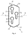
- the separating knife 7 at a first, in the direction of cutting movement 9 facing end portion has a first guide surface 15 which in the plane of the drawing in Fig. 4 corresponding vertical projection on the surface spanned by the filling opening 3 at an angle of approximately 28 ° obliquely to the closing direction 5 extends.
- the first guide surface 15 Starting from the front end of the first guide surface 15 adjacent the knife edge 8 to the rear end of the first guide surface 15 farther from the knife edge 8, the first guide surface 15 extends away from the receiving shaft 2.
- the guide On the guide rail 13, the guide has a first, in the direction of the filling opening 3 projecting guide projection 16 which is arranged such that it spaced from the rear end of the first guide surface 15 when moving the shaft closure slide 4 from the open to the closed position Place on the first guide surface 15 comes to rest. In this case, the separating knife 7 is moved to the other guide rail 14 toward relative to the closure plate 6.
- the separating knife 7 has a second guide surface 17, which is mirror-symmetrical to the first guide surface 15 with respect to a symmetry line 18 extending in the closing direction 5.
- a second guide projection 19 is arranged, which is spaced in the closing direction 5 to the first guide projection 16. The second guide projection 19 is arranged such that it comes when moving the shaft closure slide 4 from the open to the closed position with a spaced from the rear end of the second guide surface 17 point of this guide surface 17 into contact and the separating blade on the guide rail 13 moves.
- the separating knife 7 has a third guide surface 20 which is approximately parallel to the second guide surface 17 and in the closing direction 5 has a greater distance from the knife edge 8 than the first guide surface 15.
- the first guide projection 16 is the third guide surface 20 facing when the second Guide surface 17 on the second guide projection 19 comes to rest.
- the separating knife 7 further has a fourth guide surface 21 which runs approximately parallel to the second guide surface 15 and in the closing direction 5 has a greater distance from the knife edge 8 than the second guide surface 17.
- the second guide projection 19 faces the fourth guide surface 21 when the first Guide surface 15 comes to rest on a third guide projection 22 which is arranged on the guide rail 13 and spaced in the closing direction 5 of the first guide projection 16.
- Fig. 3 is still recognizable that arranged on the one guide rail 13 guide projections 16, 22 are offset with the guide projections 19 of the other guide rail 14 to gap.
- each guide pin 25 protrude with their spaced from the closure plate 6 free end of their associated guide slot 23 and there have a mushroom-shaped cross-sectional widening, which engages behind the edge of the relevant guide slot 23.
- the remote from the guide rail 13 end of each guide slot 23 is connected to an extension point 26, whose cross-sectional dimensions are slightly larger than that of the cross-sectional enlargement of the guide pin 25th
- the slot closure slide 4 can be moved out of the open position against the closing direction 5 beyond the rear end of the guide rail 13 into a service position in which the guide pins 25 can be positioned at the extension points 26 to the separating knife 7 in the axial direction of the guide pin 25 of the closure plate. 6 to disassemble.
- the separating knife 7 can then be replaced if necessary against a corresponding spare part.
- the separating knife 7 When the shaft closure slide 4 is in the open position, the closed position or between them, the separating knife 7 is arranged between both sides of the filling opening 3, extending in the direction of the closing movement 5, facing each other guide grooves of the guide rails 1 3, 14. In these guide grooves, the cutting blade 7 and the closure plate 6 engage with opposite edge regions. The separating knife 7 is thereby prevented by the guide rail 13 from being positioned with the extension points 26 on the guide pin 25.
- separating knife 7 is formed as a half-blade, to which a further half-blade 27 rests flat, which is connected via the guide pin 25 fixed to the closure plate 6.
- the closure plate 6 has a handle 28.
- the handle 28 is formed by an opening which is arranged in a section of the closure plate 6 angled relative to the surface defined by the filling opening 3.
- the closure plate 6 has on its back two in the direction of the closing movement 5 extending teeth 29 which are arranged in the closed position located in the slot closing slide 4 in the plan view of the area defined by the filling opening 3 outside this.
- the toothings 29 each mesh with a drive gear 30, which is in drive connection with a drive motor. With the aid of the drive motor, the slot closure slide 4 can be displaced relative to the housing 12 in or against the closing direction 5 and the separating knife can be moved back and forth in the direction of the cutting movement 9.
Landscapes
- Life Sciences & Earth Sciences (AREA)
- Engineering & Computer Science (AREA)
- Forests & Forestry (AREA)
- Mechanical Engineering (AREA)
- Wood Science & Technology (AREA)
- Zoology (AREA)
- Food Science & Technology (AREA)
- Processing Of Meat And Fish (AREA)
- Meat, Egg Or Seafood Products (AREA)
Applications Claiming Priority (1)
| Application Number | Priority Date | Filing Date | Title |
|---|---|---|---|
| DE201010019325 DE102010019325B4 (de) | 2010-05-03 | 2010-05-03 | Vorrichtung zum Bearbeiten von Lebensmitteln |
Publications (2)
| Publication Number | Publication Date |
|---|---|
| EP2384642A2 true EP2384642A2 (fr) | 2011-11-09 |
| EP2384642A3 EP2384642A3 (fr) | 2013-01-02 |
Family
ID=44117080
Family Applications (1)
| Application Number | Title | Priority Date | Filing Date |
|---|---|---|---|
| EP11003100A Withdrawn EP2384642A3 (fr) | 2010-05-03 | 2011-04-13 | Dispositif destiné au traitement d'aliments |
Country Status (2)
| Country | Link |
|---|---|
| EP (1) | EP2384642A3 (fr) |
| DE (1) | DE102010019325B4 (fr) |
Cited By (6)
| Publication number | Priority date | Publication date | Assignee | Title |
|---|---|---|---|---|
| CN106362838A (zh) * | 2016-11-23 | 2017-02-01 | 汕头市名盛包装机械有限公司 | 一种物料切碎机 |
| CN110076848A (zh) * | 2019-05-29 | 2019-08-02 | 滁州市印科模塑有限责任公司 | 一种iml装饰件冲切装置 |
| CN112248081A (zh) * | 2020-09-30 | 2021-01-22 | 杭州伊尹健康技术有限公司 | 竖向切丁吹落式中药破碎机 |
| CN112248079A (zh) * | 2020-09-30 | 2021-01-22 | 杭州伊尹健康技术有限公司 | 水平切丁推落式中药切丁机 |
| CN112248082A (zh) * | 2020-09-30 | 2021-01-22 | 杭州伊尹健康技术有限公司 | 水平切丁吹落式中药切丁装置 |
| CN112248080A (zh) * | 2020-09-30 | 2021-01-22 | 杭州伊尹健康技术有限公司 | 缸驱动式中药切丁机 |
Families Citing this family (1)
| Publication number | Priority date | Publication date | Assignee | Title |
|---|---|---|---|---|
| CN116921759B (zh) | 2022-04-12 | 2026-03-06 | 宁德时代新能源科技股份有限公司 | 裁切装置、裁切方法及裁切设备 |
Citations (2)
| Publication number | Priority date | Publication date | Assignee | Title |
|---|---|---|---|---|
| DE9308956U1 (de) | 1993-06-16 | 1993-09-02 | Schumann, Jörg, 35274 Kirchhain | Schneidegerät |
| DE19612382C2 (de) | 1995-05-20 | 1998-07-16 | Holac Maschbau Gmbh | Vorrichtung zum Bearbeiten von Lebensmitteln, wie Fleisch und Wurst,insbesondere zum Schneiden dieses Gutes in Scheiben, Würfel- oder Streifenform |
Family Cites Families (3)
| Publication number | Priority date | Publication date | Assignee | Title |
|---|---|---|---|---|
| DE1779153A1 (de) * | 1968-07-12 | 1972-01-27 | Ernst Holz | Streifen- und Wuerfelschneidmaschine fuer Lebensmittel |
| DE102004008280B3 (de) * | 2004-02-18 | 2005-08-11 | Reifenhäuser, Uwe, Dipl.-Ing. | Schneidvorrichtung mit Trenndeckel |
| DE102007021370B3 (de) * | 2007-05-04 | 2009-01-15 | Reifenhäuser, Uwe | Verfahren und Vorrichtung zum Schneiden von Lebensmitteln in Streifen, Scheiben oder Würfel |
-
2010
- 2010-05-03 DE DE201010019325 patent/DE102010019325B4/de not_active Expired - Fee Related
-
2011
- 2011-04-13 EP EP11003100A patent/EP2384642A3/fr not_active Withdrawn
Patent Citations (2)
| Publication number | Priority date | Publication date | Assignee | Title |
|---|---|---|---|---|
| DE9308956U1 (de) | 1993-06-16 | 1993-09-02 | Schumann, Jörg, 35274 Kirchhain | Schneidegerät |
| DE19612382C2 (de) | 1995-05-20 | 1998-07-16 | Holac Maschbau Gmbh | Vorrichtung zum Bearbeiten von Lebensmitteln, wie Fleisch und Wurst,insbesondere zum Schneiden dieses Gutes in Scheiben, Würfel- oder Streifenform |
Cited By (10)
| Publication number | Priority date | Publication date | Assignee | Title |
|---|---|---|---|---|
| CN106362838A (zh) * | 2016-11-23 | 2017-02-01 | 汕头市名盛包装机械有限公司 | 一种物料切碎机 |
| CN110076848A (zh) * | 2019-05-29 | 2019-08-02 | 滁州市印科模塑有限责任公司 | 一种iml装饰件冲切装置 |
| CN112248081A (zh) * | 2020-09-30 | 2021-01-22 | 杭州伊尹健康技术有限公司 | 竖向切丁吹落式中药破碎机 |
| CN112248079A (zh) * | 2020-09-30 | 2021-01-22 | 杭州伊尹健康技术有限公司 | 水平切丁推落式中药切丁机 |
| CN112248082A (zh) * | 2020-09-30 | 2021-01-22 | 杭州伊尹健康技术有限公司 | 水平切丁吹落式中药切丁装置 |
| CN112248080A (zh) * | 2020-09-30 | 2021-01-22 | 杭州伊尹健康技术有限公司 | 缸驱动式中药切丁机 |
| CN112248080B (zh) * | 2020-09-30 | 2023-08-18 | 河南华夏药材有限公司 | 缸驱动式中药切丁机 |
| CN112248079B (zh) * | 2020-09-30 | 2023-09-12 | 浙江厚达智能科技股份有限公司 | 水平切丁推落式中药切丁机 |
| CN112248081B (zh) * | 2020-09-30 | 2023-10-24 | 浙江厚达智能科技股份有限公司 | 竖向切丁吹落式中药破碎机 |
| CN112248082B (zh) * | 2020-09-30 | 2023-10-24 | 浙江厚达智能科技股份有限公司 | 水平切丁吹落式中药切丁装置 |
Also Published As
| Publication number | Publication date |
|---|---|
| DE102010019325A1 (de) | 2011-11-03 |
| EP2384642A3 (fr) | 2013-01-02 |
| DE102010019325B4 (de) | 2012-02-16 |
Similar Documents
| Publication | Publication Date | Title |
|---|---|---|
| DE102010019325B4 (de) | Vorrichtung zum Bearbeiten von Lebensmitteln | |
| DE202016102297U1 (de) | Presse | |
| EP1832170A2 (fr) | Dispositif de coupe et de séparation d'une bande de pâte en mouvement en continu ou de manière cadencée | |
| WO2002036294A1 (fr) | Element de cisaillage a lame circulaire compact | |
| DE102015000983B4 (de) | Messerkopf für eine Produktschneidemaschine | |
| EP2898783A1 (fr) | Dispositif pour le moulage d'une masse façonnable | |
| DE1202620B (de) | Vorfuehr- und Austragvorrichtung fuer plattenfoermige Werkstuecke | |
| DE3213175C2 (de) | Streifen- und Würfelschneidmaschine | |
| EP2080599A1 (fr) | Machine destinée à couper des aliments en bandes ou en dés | |
| DE102005063454B4 (de) | Vorrichtung zum Trennen eines plastischen Tonstranges, mit einer allseitig wirksamen Kerbvorrichtung | |
| DE102007021370B3 (de) | Verfahren und Vorrichtung zum Schneiden von Lebensmitteln in Streifen, Scheiben oder Würfel | |
| EP2546034B1 (fr) | Tête porte-lame pour découpeuse de produits | |
| DE3327747C2 (de) | Vorrichtung zum Zuführen von stangenförmigem Stückgut | |
| DE20210501U1 (de) | Vorrichtung zur Zuführung von Lebensmitteln zu einer Schneideinrichtung und Schneidmaschine für Lebensmittel | |
| DE102005021038A1 (de) | Vorrichtung zum Trennen eines plastischen Tonstranges, mit einer allseitig wirksamen Kerbvorrichtung | |
| DE202010006382U1 (de) | Vorrichtung zum Bearbeiten von Lebensmitteln | |
| EP2151307A1 (fr) | Machine de coupe d'aliments, notamment de fromage | |
| DE2523203A1 (de) | Stanzgeraet zur herstellung spitzgezahnter stosskanten an furnierstreifen o.dgl. | |
| DE102020114060B4 (de) | Schnitzel-Plätter | |
| EP1785035B1 (fr) | Séparateur de blancs de poulet | |
| DE102007021369B4 (de) | Vorrichtung zum Schneiden von Lebensmitteln in Scheiben, Streifen oder Würfel | |
| EP4617021A1 (fr) | Machine à débiter | |
| DE19917390A1 (de) | Vorrichtung zum Bearbeiten eines Teigstrangs | |
| EP4442415A1 (fr) | Dispositif pour couper ou découper de la pâte | |
| DE202006017087U1 (de) | Vorrichtung zum Schneiden von Lebensmitteln, insbesondere von Fleisch, in Würfelform |
Legal Events
| Date | Code | Title | Description |
|---|---|---|---|
| AK | Designated contracting states |
Kind code of ref document: A2 Designated state(s): AL AT BE BG CH CY CZ DE DK EE ES FI FR GB GR HR HU IE IS IT LI LT LU LV MC MK MT NL NO PL PT RO RS SE SI SK SM TR |
|
| AX | Request for extension of the european patent |
Extension state: BA ME |
|
| PUAI | Public reference made under article 153(3) epc to a published international application that has entered the european phase |
Free format text: ORIGINAL CODE: 0009012 |
|
| PUAL | Search report despatched |
Free format text: ORIGINAL CODE: 0009013 |
|
| AK | Designated contracting states |
Kind code of ref document: A3 Designated state(s): AL AT BE BG CH CY CZ DE DK EE ES FI FR GB GR HR HU IE IS IT LI LT LU LV MC MK MT NL NO PL PT RO RS SE SI SK SM TR |
|
| AX | Request for extension of the european patent |
Extension state: BA ME |
|
| RIC1 | Information provided on ipc code assigned before grant |
Ipc: B26D 1/08 20060101ALI20121129BHEP Ipc: A22C 17/00 20060101AFI20121129BHEP |
|
| 17P | Request for examination filed |
Effective date: 20130422 |
|
| STAA | Information on the status of an ep patent application or granted ep patent |
Free format text: STATUS: THE APPLICATION IS DEEMED TO BE WITHDRAWN |
|
| 18D | Application deemed to be withdrawn |
Effective date: 20181101 |