EP2384679B1 - Anzeigevorrichtung für einen Filter, und Staubsauger mit einem solchen Filter als Abluftfilter - Google Patents
Anzeigevorrichtung für einen Filter, und Staubsauger mit einem solchen Filter als Abluftfilter Download PDFInfo
- Publication number
- EP2384679B1 EP2384679B1 EP11401060.6A EP11401060A EP2384679B1 EP 2384679 B1 EP2384679 B1 EP 2384679B1 EP 11401060 A EP11401060 A EP 11401060A EP 2384679 B1 EP2384679 B1 EP 2384679B1
- Authority
- EP
- European Patent Office
- Prior art keywords
- filter
- vacuum cleaner
- display device
- exhaust
- thermal expansion
- Prior art date
- Legal status (The legal status is an assumption and is not a legal conclusion. Google has not performed a legal analysis and makes no representation as to the accuracy of the status listed.)
- Not-in-force
Links
- 239000002699 waste material Substances 0.000 title 1
- 239000003550 marker Substances 0.000 claims 2
- 239000000428 dust Substances 0.000 description 14
- 238000000034 method Methods 0.000 description 4
- OKTJSMMVPCPJKN-UHFFFAOYSA-N Carbon Chemical compound [C] OKTJSMMVPCPJKN-UHFFFAOYSA-N 0.000 description 3
- 230000000875 corresponding effect Effects 0.000 description 2
- 230000001419 dependent effect Effects 0.000 description 2
- 239000000463 material Substances 0.000 description 2
- 238000012986 modification Methods 0.000 description 2
- 230000004048 modification Effects 0.000 description 2
- 230000003287 optical effect Effects 0.000 description 2
- 238000005299 abrasion Methods 0.000 description 1
- 239000002250 absorbent Substances 0.000 description 1
- 230000002745 absorbent Effects 0.000 description 1
- 238000013459 approach Methods 0.000 description 1
- 229910052799 carbon Inorganic materials 0.000 description 1
- 230000002596 correlated effect Effects 0.000 description 1
- 238000009795 derivation Methods 0.000 description 1
- 238000011161 development Methods 0.000 description 1
- 230000000694 effects Effects 0.000 description 1
- 239000012530 fluid Substances 0.000 description 1
- 238000010438 heat treatment Methods 0.000 description 1
- 239000007788 liquid Substances 0.000 description 1
- 238000012423 maintenance Methods 0.000 description 1
- 238000004519 manufacturing process Methods 0.000 description 1
- 238000005259 measurement Methods 0.000 description 1
- 239000002245 particle Substances 0.000 description 1
- 239000013618 particulate matter Substances 0.000 description 1
- 238000011045 prefiltration Methods 0.000 description 1
- 238000012360 testing method Methods 0.000 description 1
- 230000036962 time dependent Effects 0.000 description 1
Images
Classifications
-
- A—HUMAN NECESSITIES
- A47—FURNITURE; DOMESTIC ARTICLES OR APPLIANCES; COFFEE MILLS; SPICE MILLS; SUCTION CLEANERS IN GENERAL
- A47L—DOMESTIC WASHING OR CLEANING; SUCTION CLEANERS IN GENERAL
- A47L9/00—Details or accessories of suction cleaners, e.g. mechanical means for controlling the suction or for effecting pulsating action; Storing devices specially adapted to suction cleaners or parts thereof; Carrying-vehicles specially adapted for suction cleaners
- A47L9/10—Filters; Dust separators; Dust removal; Automatic exchange of filters
- A47L9/19—Means for monitoring filtering operation
Definitions
- the invention relates to a display device for a filter, in particular a filter acting as a vacuum cleaner exhaust filter.
- the display device is provided for displaying a degree of saturation of the filter.
- the invention relates to a filter with such a display device, that is, a filter combined with a display device or a system comprising the filter and the display device.
- the invention relates to a vacuum cleaner with such a filter and the use of such a filter as a vacuum cleaner exhaust filter.
- Vacuum cleaners in particular electric vacuum cleaners in a version as a household vacuum cleaner, work almost exclusively with multi-stage particle filters.
- a prefilter - preferably designed as a dust bag - and behind an exhaust filter for removing fine dust that still happens to the bag are usually in front of a vacuum cleaner fan provided.
- the latter takes e.g. nor the abrasion of carbon brushes or the like of the drive motor of the fan.
- Both filter stages must be replaced as consumables by the user of the vacuum cleaner.
- a user must be reliably and conveniently signaled when the bag or the exhaust filter must be changed as a result of reaching an upper limit for a filling or saturation.
- For the dust bag sensors are usually used, which operate on the differential pressure principle.
- the exhaust filter is known to use an operating time of the filter as a criterion for a required replacement.
- a time counter is considered, which is reset manually after inserting the exhaust filter by the user and the expiration of a fixed operating time signals the necessary change of the filter.
- the algorithm for this and necessary operating and display elements are implemented in a vacuum cleaner control or part of the vacuum cleaner control.
- a vacuum cleaner is known with a display device that indicates the need for a change of the exhaust filter depending on the measurements of a temperature and a pressure sensor.
- the two sensors are linked together via a control so that when the limit for the temperature at the engine and / or exhaust air flow of the engine is exceeded and at the same time a limit for the negative pressure in the dust filter chamber of the vacuum cleaner is not exceeded, the control operates a filter change indicator.
- the DE 102 29 796 describes a filter with a temperature-dependent integrating consumption indicator.
- the color of the indicator changes depending on the temperature always when the vacuum cleaner is operated for a long time.
- the DE 602 05 753 T describes time-dependent consumption indicators that must be activated by the user by opening a fluid store. A colored indicator liquid diffuses into an absorbent material in the consumption indicator, which then discolors over time and thus represents a measure of the useful life.
- the operating time as a criterion for a required filter change does not take into account or not yet optimally an actual load situation of the filter, because the pure, linear time sequence is not able to represent the actual and over time varying usage behavior.
- a filter in particular a vacuum cleaner exhaust filter, with means for generating a consumption or saturation-compliant filter change signal.
- a due to thermal expansion mechanically operable filter change indicator is provided in a display device for a filter, in particular a vacuum cleaner exhaust filter.
- the operation of the display device that is, a filter that acts as Staubsaugerabluftfilter, during operation of the vacuum cleaner, resulting heat, in particular exhaust heat, is a good measure of a useful life and type of the filter, so that from a thermal expansion of a consumption and / or saturable filter change signal is derivable.
- a derivation operable due to thermal expansion filter change indicator is provided for such a derivation operable due to thermal expansion filter change indicator.
- the filter change indicator can, for. B. be read by the operator and thus acts as an optical signal for a necessary filter change to the user.
- a filter of the type described here and hereinafter is, in particular, a vacuum cleaner exhaust filter, that is to say a filter which is arranged in the exhaust air flow of the suction fan of an electric vacuum cleaner, which is e.g. acts as a particulate matter or hygiene filter and is sometimes referred to as a blow-out or post-filter.
- the display device for actuating the filter change indicator due to thermal expansion comprises an actuator that includes a heat-expandable medium.
- the actuating element is flowed together with the display device of the air to be filtered, so that during operation results in a heating, which leads to a thermal expansion of the existing medium in the actuator.
- This thermal expansion is converted by the actuator into a mechanical actuation of the filter change indicator.
- Such an actuator is simple and low maintenance despite the mechanical effect.
- the actuating element comprises an actuating lever which is movable with thermal expansion of the medium.
- the actuating lever is a particularly simple way for a mechanical contact between the actuating element and the filter change indicator, so that its actuation can be effected by the actuating lever of the actuating element.
- a heat-expandable medium for the actuator wax comes into consideration. Such a medium reacts sufficiently for the intended application with a thermal expansion to a temperature increase.
- a heat-expandable medium such as wax or the like is sufficiently viscous, so that z. B. for a movable with the wax at thermal expansion operating lever no special precautions for its positioning and adjustment are provided.
- a filter change indicator is preferably a counter or the like into consideration.
- a counter as a filter change indicator, this can register each actuation by the actuator and provide a display of a number of actuations above a predetermined or predeterminable threshold value, which alerts a user to the need for filter change.
- the counter can assume a position acting as a change mark, wherein the counter is configured so that the change mark adjusts after a predetermined number of actuation operations by the actuator.
- the counter can be configured as an up-counting or down-counting counter.
- the counter In the delivery condition of the display device or a filter combined with such a display device, the counter is set to a start configuration correlated with the filter or can be set to such a start configuration.
- the counter counts up or down on each actuation by the actuator until the counter assumes the position acting as a change mark.
- the indication of the change flag by the counter then acts as a signal to the user for a required filter change.
- the display device of the type described here and below can be combined with basically any filters, so that the invention accordingly also relates to a filter with a display device described here and below.
- filter is especially a so-called vacuum cleaner exhaust filter into consideration.
- the invention thus also relates to a vacuum cleaner with such a display device or a vacuum cleaner with a combined with such a display device filter, in particular a vacuum cleaner exhaust filter with a display device according to the invention.
- the exhaust air flow of the suction fan is a good measure of the operating mode and the operating time of the vacuum cleaner and thus the load on the filter, so that a position of the filter change indicator after a number of actuation operations by the actuator information about a saturation of the filter or possibly already reached Saturation limit of the filter.
- the invention finally also relates to a use of a filter with a display device, as described here and below, as a vacuum cleaner exhaust filter in the exhaust air stream of a suction fan of an electric vacuum cleaner.
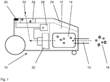
- Fig. 1 shows a vacuum cleaner 10 known per se, which has a dust chamber 12 with there attachable dust bag 14.
- a dust bag 14 supplied dust via a suction hose 16 is collected.
- the dust 18 in turn is transported by the suction flow 20, the blower 22 (vacuum cleaner fan) generated.
- the dust chamber 12 is closed by means of a dust chamber cover 24. Finer components of the dust 18 that pass through the dust bag 14, pass through the exhaust air or the suction flow 20 of the blower 22 in a vacuum cleaner exhaust filter 26th
- the vacuum cleaner 10 comprises a control computer 28, which is in operative connection with a vacuum cleaner 10 arranged on the operating and display unit 30. About the signals of the control and display unit 30, the suction power of the blower 22 and thus a quantity of recordable dust 18 is set by the control computer 28 through the vacuum cleaner 10. Further, in individual embodiments of the known vacuum cleaner 10, the control and display unit 30 indicates a change of the vacuum cleaner exhaust filter 26 which becomes necessary as a function of z. In a vacuum cleaner 10 with such functionality after the replacement of the vacuum cleaner exhaust filter 26 via the control and display unit 30 of the operating time counter is reset.
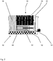
- Fig. 2 shows an embodiment of a display device 40 in a with a filter 42 shown only partially, for. B. a vacuum cleaner exhaust filter 26 ( Fig. 1 ), combined configuration.
- the filter 42 is a so-called HEPA filter, which comprises an activated carbon layer 44 on a filter inlet side and a filter medium 46 following this.
- the display device 40 is integrated into the filter 42 so that it laterally adjoins the filter medium 46. Any other position is just as conceivable for the display device 40, z. As a surrounded on all sides by the filter medium 46 position.
- the display device 40 includes as a heat-expensible filter change indicator 48 a counter.
- the operation of the filter change indicator 48 is carried out with an actuating element 50. This includes for actuating the filter change indicator 48 due to thermal expansion of a heat-expandable medium 52, z. B. wax.
- an actuating lever 54 is held, which with appropriate thermal expansion of the heat-expandable medium 52 the Filter change indicator 48 is actuated.
- a corresponding thereto and actuatable by the actuating lever 54 of the actuating element 50 counteracting lever is shown for actuating the filter change indicator 48.
- the filter change indicator 48 is shown as a counter and, more particularly, it is a mechanical counter that performs a count step upon each actuation by the actuator 50. Notwithstanding the illustrated label of the counter with Arabic numerals is also a use of a color code or the like into consideration, so that z. B. when reaching a predetermined or predetermined counter reading of the counter at a functioning as a change display 56 visible side three, or depending on the number of rollers of the counter, one or more red fields are, which represent a filter change signal for the user of the filter 42 in combination.
- a display device 40 for a filter 42 in particular a vacuum cleaner exhaust filter 26, with a due to thermal expansion mechanically actuated filter change indicator 48 is given, so that the thermal expansion as a measure of the type of use and duration can be used by the filter 42 and with due to such thermal expansion of a user perceptible signal, in particular in the form of an optical indication generated, the information about a degree of saturation or possibly already reached saturation upper limit of the filter 42.
Landscapes
- Engineering & Computer Science (AREA)
- Mechanical Engineering (AREA)
- Filtering Of Dispersed Particles In Gases (AREA)
- Filters For Electric Vacuum Cleaners (AREA)
- Electric Vacuum Cleaner (AREA)
Description
- Die Erfindung betrifft eine Anzeigevorrichtung für einen Filter, insbesondere einen als Staubsaugerabluftfilter fungierenden Filter. Die Anzeigevorrichtung ist zur Darstellung eines Sättigungsgrads des Filters vorgesehen. Weiter betrifft die Erfindung einen Filter mit einer solchen Anzeigevorrichtung, also einen mit einer Anzeigevorrichtung kombinierten Filter oder ein System, das den Filter und die Anzeigevorrichtung umfasst. Weiter betrifft die Erfindung einen Staubsauger mit einem solchen Filter und die Verwendung eines solchen Filters als Staubsaugerabluftfilter.
- Staubsauger, insbesondere Elektrostaubsauger in einer Ausführung als Haushaltsstaubsauger, arbeiten fast ausschließlich mit mehrstufigen Partikelfiltern. So sind in der Regel vor einem Staubsaugergebläse ein Vorfilter - vorzugsweise als Staubbeutel ausgeführt - und dahinter ein Abluftfilter zur Beseitigung von Feinstaub, der den Beutel noch passiert, vorgesehen. Letzterer nimmt z.B. noch den Abrieb von Kohlebürsten oder dergleichen des Antriebsmotors des Gebläses auf. Beide Filterstufen müssen als Verbrauchsmaterial vom Benutzer des Staubsaugers ausgetauscht werden. Einem Benutzer muss dazu zuverlässig und gebrauchsgerecht signalisiert werden, wann der Beutel oder der Abluftfilter in Folge einer erreichten Obergrenze für eine Füllung oder Sättigung gewechselt werden muss. Für den Staubbeutel werden üblicherweise Sensoren verwendet, die nach dem Differenzdruckprinzip arbeiten. Für den Abluftfilter ist bekannt, eine Betriebszeit des Filters als Kriterium für einen erforderlichen Austausch heranzuziehen. Hierzu kommt ein Zeitzähler in Betracht, der nach dem Einlegen des Abluftfilters manuell durch den Benutzer zurückgesetzt wird und der nach Ablauf einer fest vorgegebenen Betriebszeit den notwendigen Wechsel des Filters signalisiert. Der Algorithmus hierfür sowie notwendige Bedien- und Anzeigeelemente sind in einer Staubsaugersteuerung implementiert bzw. Bestandteil der Staubsaugersteuerung.
- Aus der
DE 37 12233 A1 ist ein Staubsauger bekannt mit einer Anzeigevorrichtung, die in Abhängigkeit von den Messwerten eines Temperatur- und eines Drucksensors die Notwendigkeit eines Wechsels des Abluftfilters anzeigt. Die beiden Sensoren sind dabei über ein Steuerelement so miteinander verknüpft, dass wenn der Grenzwert für die Temperatur am Motor und/oder Abluftstrom des Motors überschritten wird und gleichzeitig ein Grenzwert für den Unterdruck in der Staubfilterkammer des Staubsaugers nicht überschritten wird das Steuerelement einen Filterwechselindikator betätigt. - Die
DE 102 29 796 beschreibt einen Filter mit einem temperaturabhängig integrierenden Verbrauchsindikator. Die Farbe des Indikators ändert sich temperaturabhängig immer dann, wenn der Staubsauger längere Zeit betrieben wird. DieDE 602 05 753 T beschreibt zeitabhängige Verbrauchsindikatoren, die vom Benutzer durch Öffnen eines Flüssigkeitsspeichers aktiviert werden müssen. Eine farbige Indikatorflüssigkeit diffundiert in ein im Verbrauchsindikator befindliches saugfähiges Material, das sich dann zeitabhängig verfärbt und damit einen Maßstab für die Nutzungsdauer darstellt. - Die Betriebszeit als Kriterium für einen erforderlichen Filterwechsel berücksichtigt allerdings nicht oder noch nicht optimal eine tatsächliche Belastungssituation des Filters, weil der reine, lineare Zeitablauf nicht das tatsächliche und über der Zeit variierende Benutzungsverhalten abzubilden vermag.
- Eine Aufgabe der vorliegenden Erfindung besteht entsprechend darin, einen Filter, insbesondere einen Staubsaugerabluftfilter, mit Mitteln zur Generierung eines verbrauchs- bzw. sättigungskonformen Filterwechselsignals anzugeben.
- Diese Aufgabe wird erfindungsgemäß mit den Merkmalen des Anspruchs 1 gelöst. Dazu ist bei einer Anzeigevorrichtung für einen Filter, insbesondere einen Staubsaugerabluftfilter, ein aufgrund von Wärmeausdehnung mechanisch betätigbarer Filterwechselindikator, vorgesehen. Die sich im Betrieb der Anzeigevorrichtung, also bei einem Filter, der als Staubsaugerabluftfilter fungiert, beim Betrieb des Staubsaugers, ergebende Wärme, insbesondere Abluftwärme, ist ein gutes Maß für eine Nutzungsdauer und -art des Filters, so dass aus einer Wärmeausdehnung ein Verbrauchs- und/oder sättigungskonformes Filterwechselsignal ableitbar ist. Beim Ansatz gemäß der Erfindung ist für eine derartige Ableitung ein aufgrund von Wärmeausdehnung betätigbarer Filterwechselindikator vorgesehen. Bei einem bestimmten Wärmeeintrag, also einer bestimmten Nutzungsdauer oder -art, ergibt sich eine Wärmeausdehnung, die eine Betätigung des Filterwechselindikators nach sich zieht. Der Filterwechselindikator kann z. B. vom Bediener abgelesen werden und fungiert damit als optisches Signal für einen notwendigen Filterwechsel an den Benutzer.
- Ein Filter der hier und nachfolgend beschriebenen Art ist insbesondere ein Staubsaugerabluftfilter, also ein Filter, der im Abluftstrom des Sauggebläses eines Elektrostaubsaugers angeordnet ist, der z.B. als Feinstaub- oder Hygienefilter fungiert und mitunter auch als Ausblas- oder Nachfilter bezeichnet wird.
- Vorteilhafte Ausgestaltungen der Erfindung sind Gegenstand der Unteransprüche. Dabei verwendete Rückbeziehungen weisen auf die weitere Ausbildung des Gegenstands des Hauptanspruchs durch die Merkmale des jeweiligen Unteranspruchs hin.
- Des Weiteren ist im Hinblick auf eine Auslegung der Ansprüche bei einer näheren Konkretisierung eines Merkmals in einem nachgeordneten Anspruch davon auszugehen, dass eine derartige Beschränkung in den jeweils vorangehenden Ansprüchen nicht vorhanden ist.
- Bevorzugt umfasst die Anzeigevorrichtung zum Betätigen des Filterwechselindikators aufgrund von Wärmeausdehnung ein Betätigungselement, das ein wärmeausdehnungsfähiges Medium beinhaltet. Das Betätigungselement wird zusammen mit der Anzeigevorrichtung von der zu filternden Luft angeströmt, so dass sich im Betrieb eine Erwärmung ergibt, die zu einer Wärmeausdehnung des in dem Betätigungselement vorhandenen Mediums führt. Diese Wärmeausdehnung wird durch das Betätigungselement in eine mechanische Betätigung des Filterwechselindikators umgesetzt. Ein solches Betätigungselement ist trotz der mechanischen Wirkungsweise einfach und wartungsarm.
- Bevorzugt umfasst das Betätigungselement einen Betätigungshebel, der mit einer Wärmeausdehnung des Mediums beweglich ist. Der Betätigungshebel ist eine besonders einfache Möglichkeit für einen mechanischen Kontakt zwischen Betätigungselement und Filterwechselindikator, so dass dessen Betätigung durch den Betätigungshebel des Betätigungselements erfolgen kann.
- Als wärmeausdehnungsfähiges Medium für das Betätigungselement kommt Wachs in Betracht. Ein solches Medium reagiert in für die geplante Anwendung ausreichender Art und Weise mit einer Wärmeausdehnung auf eine Temperaturerhöhung. Zudem ist ein wärmeausdehnungsfähiges Medium wie Wachs oder dergleichen ausreichend viskos, so dass z. B. für einen mit dem Wachs bei Wärmeausdehnung beweglichen Betätigungshebel keine besonderen Vorkehrungen für dessen Positionierung und Justierung vorzusehen sind.
- Als Filterwechselindikator kommt bevorzugt ein Zählwerk oder dergleichen in Betracht. Bei einem Zählwerk als Filterwechselindikator kann dieses jede Betätigung durch das Betätigungselement registrieren und ab einer Anzahl von Betätigungen oberhalb eines vorgegebenen oder vorgebbaren Schwellwerts eine Anzeige liefern, die einen Benutzer auf die Notwendigkeit zum Filterwechsel aufmerksam macht. Dafür kann das Zählwerk eine als Wechselmarkierung fungierende Stellung einnehmen, wobei das Zählwerk so konfiguriert ist, dass sich die Wechselmarkierung nach einer vorgegebenen Anzahl von Betätigungsvorgängen durch das Betätigungselement einstellt. Das Zählwerk kann dabei als aufwärts zählendes oder abwärts zählendes Zählwerk konfiguriert sein. Im Auslieferungszustand der Anzeigevorrichtung oder eines mit einer solchen Anzeigevorrichtung kombinierten Filters ist das Zählwerk auf eine mit dem Filter korrelierte Startkonfiguration eingestellt oder auf eine solche Startkonfiguration einstellbar. Im Betrieb zählt das Zählwerk bei jeder Betätigung durch das Betätigungselement aufwärts oder abwärts, bis das Zählwerk die als Wechselmarkierung fungierende Stellung einnimmt. Die Anzeige der Wechselmarkierung durch das Zählwerk fungiert dann als Signal an den Benutzer für einen erforderlichen Filterwechsel.
- Die Anzeigevorrichtung der hier und nachfolgend beschriebenen Art kann mit grundsätzlich beliebigen Filtern kombiniert werden, so dass die Erfindung entsprechend auch einen Filter mit einer hier und nachfolgend beschriebenen Anzeigevorrichtung betrifft. Als Filter kommt besonders ein so genannter Staubsaugerabluftfilter in Betracht. Insgesamt betrifft die Erfindung damit auch einen Staubsauger mit einer solchen Anzeigevorrichtung oder einen Staubsauger mit einem mit einer solchen Anzeigevorrichtung kombinierten Filter, insbesondere einem Staubsaugerabluftfilter mit einer Anzeigevorrichtung gemäß der Erfindung. Wenn der mit der Anzeigevorrichtung kombinierte Filter als Staubsaugerabluftfilter in einem Abluftkanal eines vom Staubsauger umfassten Sauggebläses fungiert, ergibt sich die Wärmeausdehnung für den aufgrund von Wärmeausdehnung mechanisch betätigbaren Filterwechselindikator im Betrieb des Staubsaugers aufgrund des Abluftstroms des Sauggebläses. Der Abluftstrom des Sauggebläses ist ein gutes Maß für die Betriebsart und die Betriebsdauer des Staubsaugers und damit für die Belastung des Filters, so dass eine Stellung des Filterwechselindikators nach einer Anzahl von Betätigungsvorgängen durch die Betätigungsvorrichtung Auskunft über eine Sättigung des Filters oder eine evtl. bereits erreichte Sättigungsgrenze des Filters gibt.
- Damit betrifft die Erfindung schließlich auch eine Verwendung eines Filters mit einer Anzeigevorrichtung, wie hier und nachfolgend beschrieben, als Staubsaugerabluftfilter im Abluftstrom eines Sauggebläses eines Elektrostaubsaugers.
- Nachfolgend wird ein Ausführungsbeispiel der Erfindung anhand der Zeichnung näher erläutert. Einander entsprechende Gegenstände oder Elemente sind in allen Figuren mit den gleichen Bezugszeichen versehen.
- Das oder jedes Ausführungsbeispiel ist nicht als Einschränkung der Erfindung zu verstehen. Vielmehr sind im Rahmen der vorliegenden Offenbarung zahlreiche Abänderungen und Modifikationen möglich, insbesondere solche Varianten, Elemente und Kombinationen und/oder Materialien, die zum Beispiel durch Kombination oder Abwandlung von einzelnen in Verbindung mit den in der allgemeinen Beschreibung, der oder jeder Ausführungsform sowie den Ansprüchen beschriebenen und in den Zeichnungen enthaltenen Merkmalen bzw. Elementen oder Verfahrensschritten für den Fachmann im Hinblick auf die Lösung der Aufgabe entnehmbar sind und durch kombinierbare Merkmale zu einem neuen Gegenstand oder zu neuen Verfahrensschritten oder Verfahrensschrittfolgen führen, auch soweit sie Herstell-, Prüf- und Arbeitsverfahren betreffen.
- Es zeigen
- Fig. 1
- einen an sich bekannten Staubsauger und
- Fig. 2
- eine Ausführungsform einer Anzeigevorrichtung gemäß der Erfindung in einem nur teilweise dargestellten Filter wie er z. B. in einem Staubsauger verwendbar ist.
-
Fig. 1 zeigt einen an sich bekannten Staubsauger 10, der einen Staubraum 12 mit dort anbringbarem Staubbeutel 14 aufweist. In dem Staubbeutel 14 wird über einen Saugschlauch 16 zugeführter Staub 18 gesammelt. Der Staub 18 wiederum wird vom Saugstrom 20 transportiert, den ein Gebläse 22 (Staubsaugergebläse) erzeugt. Der Staubraum 12 wird mittels eines Staubraumdeckels 24 verschlossen. Feinere Bestandteile des Staubs 18, die den Staubbeutel 14 passieren, gelangen über die Abluft oder den Saugstrom 20 des Gebläses 22 in einen Staubsaugerabluftfilter 26. - Der Staubsauger 10 umfasst einen Steuerrechner 28, der mit einer am Staubsauger 10 angeordneten Bedien- und Anzeigeeinheit 30 in Wirkverbindung steht. Über die Signale der Bedien- und Anzeigeeinheit 30 wird vom Steuerrechner 28 die Saugleistung des Gebläses 22 und damit eine Menge aufnehmbaren Staubs 18 durch den Staubsauger 10 eingestellt. Ferner signalisiert bei einzelnen Ausführungsformen bekannter Staubsauger 10 die Bedien- und Anzeigeeinheit 30 einen notwendig werdenden Wechsel des Staubsaugerabluftfilters 26 in Abhängigkeit z. B. von einer vom Steuerrechner 28 ermittelten Betriebszeit des Staubsaugers 10. Bei einem Staubsauger 10 mit einer solchen Funktionalität wird nach erfolgtem Wechsel des Staubsaugerabluftfilters 26 über die Bedien- und Anzeigeeinheit 30 der Betriebszeitzähler zurückgesetzt.
-
Fig. 2 zeigt eine Ausführungsform einer Anzeigevorrichtung 40 in einer mit einem nur teilweise dargestellten Filter 42, z. B. einem Staubsaugerabluftfilter 26 (Fig. 1 ), kombinierten Konfiguration. Bei dem Filter 42 handelt es sich um einen so genannten HEPA-Filter, der an einer Filtereingangsseite eine Aktivkohleschicht 44 und im Anschluss an diese ein Filtermedium 46 umfasst. Die Anzeigevorrichtung 40 ist so in den Filter 42 integriert, dass diese sich seitlich an das Filtermedium 46 anschließt. Jede andere Position ist für die Anzeigevorrichtung 40 genauso denkbar, z. B. eine allseitig vom Filtermedium 46 umgebene Position. - Die Anzeigevorrichtung 40 umfasst als aufgrund von Wärmeausdehnung betätigbarem Filterwechselindikator 48 ein Zählwerk. Die Betätigung des Filterwechselindikators 48 erfolgt mit einem Betätigungselement 50. Dieses beinhaltet zum Betätigen des Filterwechselindikators 48 aufgrund von Wärmeausdehnung ein wärmeausdehnungsfähiges Medium 52, z. B. Wachs. In dem wärmeausdehnungsfähigen Medium 52, und ansonsten durch ein Gehäuse des Betätigungselements 50, wird ein Betätigungshebel 54 gehalten, der bei entsprechender Wärmeausdehnung des wärmeausdehnungsfähigen Mediums 52 den Filterwechselindikator 48 betätigt. Beim dargestellten Ausführungsbeispiel ist zur Betätigung des Filterwechselindikators 48 ein zu diesem gehöriger und vom Betätigungshebel 54 des Betätigungselements 50 betätigbarer Gegenbetätigungshebel dargestellt.
- Bei der dargestellten Ausführungsform ist der Filterwechselindikator 48 als Zählwerk gezeigt, und insbesondere handelt es sich um ein mechanisches Zählwerk, das bei jeder Betätigung durch das Betätigungselement 50 einen Zählschritt ausführt. Abweichend von der dargestellten Beschriftung des Zählwerks mit arabischen Ziffern kommt auch eine Verwendung eines Farbcodes oder dergleichen in Betracht, so dass sich z. B. beim Erreichen eines vorgegebenen oder vorgebbaren Zählerstands des Zählwerks an einer als Wechselanzeige 56 fungierenden Sichtseite drei, oder je nach Walzenanzahl des Zählwerks, ein oder mehrere rote Felder befinden, die in Kombination für den Benutzer des Filters 42 ein Filterwechselsignal darstellen.
- Zusammenfassend lässt sich die vorliegende Erfindung damit kurz wie folgt darstellen: Es wird eine Anzeigevorrichtung 40 für einen Filter 42, insbesondere einen Staubsaugerabluftfilter 26, mit einem aufgrund von Wärmeausdehnung mechanisch betätigbaren Filterwechselindikator 48 angegeben, so dass die Wärmeausdehnung als Maß für die Nutzungsart und -dauer des Filters 42 herangezogen werden kann und mit aufgrund einer solchen Wärmeausdehnung ein vom Benutzer wahrnehmbares Signal, insbesondere in Form eines optischen Hinweises, generiert wird, das Auskunft über einen Sättigungsgrad oder eine evtl. bereits erreichte Sättigungsobergrenze des Filters 42 gibt.
Claims (10)
- Anzeigevorrichtung (40) für einen Filter (42), insbesondere einen Staubsaugerabluftfilter (26) mit einem Filterwechselindikator (48),
dadurch gekennzeichnet,
dass der Filterwechselindikator (48) aufgrund von Wärmeausdehnung mechanisch betätigbar ist. - Anzeigevorrichtung (40) nach Anspruch 1, mit einem Betätigungselement (50) zum Betätigen des Filterwechselindikators (48) aufgrund von Wärmeausdehnung, wobei das Betätigungselement (50) ein wärmeausdehnungsfähiges Medium (52) beinhaltet.
- Anzeigevorrichtung (40) nach Anspruch 2, wobei das Betätigungselement (50) einen Betätigungshebel (54) umfasst, der mit einer Wärmeausdehnung des Mediums (52) beweglich ist.
- Anzeigevorrichtung (40) nach Anspruch 2 oder 3, mit einem Wachs als Medium (52).
- Anzeigevorrichtung (40) nach einem der vorangehenden Ansprüche, mit einem Zählwerk als Filterwechselindikator (48).
- Anzeigevorrichtung (40) nach einem der Ansprüche 2 bis 4 und Anspruch 5, wobei das Zählwerk eine als Wechselmarkierung fungierende Stellung einnehmen kann und wobei das Zählwerk so konfiguriert ist, dass sich die Wechselmarkierung nach einer vorgegebenen Anzahl von Betätigungsvorgängen durch das Betätigungselement (50) einstellt.
- Filter (42) mit einer Anzeigevorrichtung (40) nach einem der vorangehenden Ansprüche.
- Staubsauger (10) mit einem Filter (42) nach Anspruch 7.
- Staubsauger (10) nach Anspruch 8, wobei der Filter (42) als Staubsaugerabluftfilter (26) in einem Abluftstromkanal eines vom Staubsauger (10) umfassten Sauggebläses fungiert und wobei sich die Wärmeausdehnung im Betrieb des Staubsaugers (10) aufgrund des Abluftstroms des Sauggebläses ergibt.
- Verwendung eines Filters (42) nach Anspruch 7 als Staubsaugerabluftfilter (26) im Abluftstrom eines Sauggebläses eines Elektrostaubsaugers (10).
Applications Claiming Priority (1)
| Application Number | Priority Date | Filing Date | Title |
|---|---|---|---|
| DE102010016789A DE102010016789B4 (de) | 2010-05-05 | 2010-05-05 | Anzeigevorrichtung für einen Filter, Staubsauger und Verwendung eines solchen Filters als Staubsaugerabluftfilter |
Publications (3)
| Publication Number | Publication Date |
|---|---|
| EP2384679A2 EP2384679A2 (de) | 2011-11-09 |
| EP2384679A3 EP2384679A3 (de) | 2013-09-04 |
| EP2384679B1 true EP2384679B1 (de) | 2019-03-27 |
Family
ID=44359504
Family Applications (1)
| Application Number | Title | Priority Date | Filing Date |
|---|---|---|---|
| EP11401060.6A Not-in-force EP2384679B1 (de) | 2010-05-05 | 2011-04-13 | Anzeigevorrichtung für einen Filter, und Staubsauger mit einem solchen Filter als Abluftfilter |
Country Status (3)
| Country | Link |
|---|---|
| US (1) | US8647408B2 (de) |
| EP (1) | EP2384679B1 (de) |
| DE (1) | DE102010016789B4 (de) |
Families Citing this family (4)
| Publication number | Priority date | Publication date | Assignee | Title |
|---|---|---|---|---|
| US9058729B2 (en) * | 2012-09-13 | 2015-06-16 | GM Global Technology Operations LLC | In-situ overheat alert for equipment |
| DE102013104996A1 (de) | 2013-05-15 | 2014-11-20 | Miele & Cie. Kg | Staubsauger mit Filterwechselanzeige |
| DE102018216306B3 (de) | 2018-09-25 | 2020-01-16 | BSH Hausgeräte GmbH | Verfahren zur Überwachung einer austauschbaren Einheit, sowie Hausgerät mit einer austauschbaren Einheit |
| CN109199232A (zh) * | 2018-10-11 | 2019-01-15 | 珠海格力电器股份有限公司 | 吸尘器及其过滤网更换提醒方法、装置和控制器 |
Family Cites Families (11)
| Publication number | Priority date | Publication date | Assignee | Title |
|---|---|---|---|---|
| DE3712233C2 (de) * | 1987-04-10 | 1994-05-11 | Licentia Gmbh | Staubsauger |
| SE465060B (sv) * | 1989-08-30 | 1991-07-22 | Electrolux Ab | Indikeringsanordning foer dammsugare |
| US6026539A (en) * | 1998-03-04 | 2000-02-22 | Bissell Homecare, Inc. | Upright vacuum cleaner with full bag and clogged filter indicators thereon |
| GB0116878D0 (en) * | 2001-07-11 | 2001-09-05 | Timestrip Ltd | Time indicator |
| JP4339701B2 (ja) * | 2002-04-03 | 2009-10-07 | スリーエム イノベイティブ プロパティズ カンパニー | 時間または時間−温度表示物品 |
| DE10229796A1 (de) | 2002-07-03 | 2004-01-15 | Vorwerk & Co. Interholding Gmbh | Filter für einen Staubsauger sowie Staubsauger mit einem Vorfilter und einem Ausblasfilter |
| US7303613B2 (en) * | 2003-12-11 | 2007-12-04 | Euro-Pro Operating, Llc | Filter sensor and indicator for vacuum cleaners |
| US7281345B2 (en) | 2004-02-04 | 2007-10-16 | Bedford Industries, Inc. | Merchandise labeling |
| JP4789083B2 (ja) * | 2004-07-15 | 2011-10-05 | 株式会社ジークエスト | 温度感知シール |
| US7509707B2 (en) * | 2006-02-06 | 2009-03-31 | Panasonic Corporation Of North America | Floor cleaning apparatus with dirt detection sensor |
| WO2009046122A2 (en) * | 2007-10-01 | 2009-04-09 | Bay Materials, Llc | Temperature-switching materials having improved strength and thermal properties |
-
2010
- 2010-05-05 DE DE102010016789A patent/DE102010016789B4/de not_active Expired - Fee Related
-
2011
- 2011-04-13 EP EP11401060.6A patent/EP2384679B1/de not_active Not-in-force
- 2011-04-27 US US13/094,883 patent/US8647408B2/en not_active Expired - Fee Related
Non-Patent Citations (1)
| Title |
|---|
| None * |
Also Published As
| Publication number | Publication date |
|---|---|
| US20110271832A1 (en) | 2011-11-10 |
| DE102010016789B4 (de) | 2012-01-12 |
| EP2384679A2 (de) | 2011-11-09 |
| DE102010016789A1 (de) | 2011-11-10 |
| EP2384679A3 (de) | 2013-09-04 |
| US8647408B2 (en) | 2014-02-11 |
Similar Documents
| Publication | Publication Date | Title |
|---|---|---|
| EP2384679B1 (de) | Anzeigevorrichtung für einen Filter, und Staubsauger mit einem solchen Filter als Abluftfilter | |
| EP2153768B1 (de) | Verfahren und Vorrichtung zur Bestimmung des Füllgrades eines in einem Staubsauger angeordneten Sammelorgans | |
| EP3644816B1 (de) | Filterabreinigung | |
| DE2243071A1 (de) | Filtriereinrichtung fuer luft | |
| EP2612582B1 (de) | Staubsauger und Verfahren zum Betrieb eines Staubsaugers | |
| EP2384678B1 (de) | Staubsauger mit filterwechselindikator | |
| EP2868987A1 (de) | Filterkonstruktion sowie diese umfassendes Filtersystem | |
| EP1981817B1 (de) | Wechselanzeige für eine wasserfiltervorrichtung | |
| EP1229989A1 (de) | Filtergerät zum filtern von druckluft | |
| DE102015218007C5 (de) | Dunstabzugsvorrichtung und Verfahren zur Überwachung des Verschmutzungsgrades eines Geruchsfilters | |
| DE1186992B (de) | Automatischer Staubsauger | |
| EP2386237B1 (de) | Filter mit Verbrauchsindikator, und Staubsauger mit einem solchen Filter | |
| EP1517633A1 (de) | Filter f r einen staubsauger sowie staubsauger mit einem vor filter und einem ausblasfilter | |
| DE102007060847A1 (de) | Staubsauger mit einer Abluftfiltereinrichtung | |
| DE10321919A1 (de) | Staubsauger mit einer Steuerungseinrichtung für eine Reinigungsvorrichtung für Keramikfilter | |
| EP1454097B1 (de) | Standzeiterfassungsvorrichtung für einen filter einer dunstabzugshaube | |
| DE102015225365A1 (de) | Staubauffangbehälter für ein Elektrowerkzeug | |
| WO2003041553A1 (de) | Reinigungsgerät | |
| DE3526793A1 (de) | Luftreinigungsgeraet | |
| EP3908392B1 (de) | Filtervorrichtung für eine saugmaschine und saugmaschine | |
| WO1996023668A1 (de) | Filtersystem mit selbsttätigem filterwechsel für kraftfahrzeuge | |
| DE1244715B (de) | Filter mit auswechselbarem Filterelement | |
| DE102012100052A1 (de) | Staubsauger mit einer Staubflussanzeigevorrichtung | |
| DE102010016790A1 (de) | Staubsauger mit einem Filter | |
| DE4025482A1 (de) | Anzeigevorrichtung fuer staubsauger |
Legal Events
| Date | Code | Title | Description |
|---|---|---|---|
| AK | Designated contracting states |
Kind code of ref document: A2 Designated state(s): AL AT BE BG CH CY CZ DE DK EE ES FI FR GB GR HR HU IE IS IT LI LT LU LV MC MK MT NL NO PL PT RO RS SE SI SK SM TR |
|
| AX | Request for extension of the european patent |
Extension state: BA ME |
|
| PUAI | Public reference made under article 153(3) epc to a published international application that has entered the european phase |
Free format text: ORIGINAL CODE: 0009012 |
|
| PUAL | Search report despatched |
Free format text: ORIGINAL CODE: 0009013 |
|
| AK | Designated contracting states |
Kind code of ref document: A3 Designated state(s): AL AT BE BG CH CY CZ DE DK EE ES FI FR GB GR HR HU IE IS IT LI LT LU LV MC MK MT NL NO PL PT RO RS SE SI SK SM TR |
|
| AX | Request for extension of the european patent |
Extension state: BA ME |
|
| RIC1 | Information provided on ipc code assigned before grant |
Ipc: A47L 9/19 20060101AFI20130731BHEP |
|
| 17P | Request for examination filed |
Effective date: 20140304 |
|
| RBV | Designated contracting states (corrected) |
Designated state(s): AL AT BE BG CH CY CZ DE DK EE ES FI FR GB GR HR HU IE IS IT LI LT LU LV MC MK MT NL NO PL PT RO RS SE SI SK SM TR |
|
| GRAP | Despatch of communication of intention to grant a patent |
Free format text: ORIGINAL CODE: EPIDOSNIGR1 |
|
| STAA | Information on the status of an ep patent application or granted ep patent |
Free format text: STATUS: GRANT OF PATENT IS INTENDED |
|
| INTG | Intention to grant announced |
Effective date: 20181129 |
|
| GRAS | Grant fee paid |
Free format text: ORIGINAL CODE: EPIDOSNIGR3 |
|
| GRAA | (expected) grant |
Free format text: ORIGINAL CODE: 0009210 |
|
| STAA | Information on the status of an ep patent application or granted ep patent |
Free format text: STATUS: THE PATENT HAS BEEN GRANTED |
|
| REG | Reference to a national code |
Ref country code: DE Ref legal event code: R084 Ref document number: 502011015529 Country of ref document: DE |
|
| AK | Designated contracting states |
Kind code of ref document: B1 Designated state(s): AL AT BE BG CH CY CZ DE DK EE ES FI FR GB GR HR HU IE IS IT LI LT LU LV MC MK MT NL NO PL PT RO RS SE SI SK SM TR |
|
| REG | Reference to a national code |
Ref country code: GB Ref legal event code: FG4D Free format text: NOT ENGLISH |
|
| REG | Reference to a national code |
Ref country code: CH Ref legal event code: EP |
|
| REG | Reference to a national code |
Ref country code: DE Ref legal event code: R096 Ref document number: 502011015529 Country of ref document: DE |
|
| REG | Reference to a national code |
Ref country code: AT Ref legal event code: REF Ref document number: 1111996 Country of ref document: AT Kind code of ref document: T Effective date: 20190415 |
|
| REG | Reference to a national code |
Ref country code: IE Ref legal event code: FG4D Free format text: LANGUAGE OF EP DOCUMENT: GERMAN |
|
| REG | Reference to a national code |
Ref country code: GB Ref legal event code: 746 Effective date: 20190408 |
|
| PG25 | Lapsed in a contracting state [announced via postgrant information from national office to epo] |
Ref country code: LT Free format text: LAPSE BECAUSE OF FAILURE TO SUBMIT A TRANSLATION OF THE DESCRIPTION OR TO PAY THE FEE WITHIN THE PRESCRIBED TIME-LIMIT Effective date: 20190327 Ref country code: NO Free format text: LAPSE BECAUSE OF FAILURE TO SUBMIT A TRANSLATION OF THE DESCRIPTION OR TO PAY THE FEE WITHIN THE PRESCRIBED TIME-LIMIT Effective date: 20190627 Ref country code: SE Free format text: LAPSE BECAUSE OF FAILURE TO SUBMIT A TRANSLATION OF THE DESCRIPTION OR TO PAY THE FEE WITHIN THE PRESCRIBED TIME-LIMIT Effective date: 20190327 Ref country code: FI Free format text: LAPSE BECAUSE OF FAILURE TO SUBMIT A TRANSLATION OF THE DESCRIPTION OR TO PAY THE FEE WITHIN THE PRESCRIBED TIME-LIMIT Effective date: 20190327 |
|
| REG | Reference to a national code |
Ref country code: NL Ref legal event code: MP Effective date: 20190327 |
|
| PG25 | Lapsed in a contracting state [announced via postgrant information from national office to epo] |
Ref country code: LV Free format text: LAPSE BECAUSE OF FAILURE TO SUBMIT A TRANSLATION OF THE DESCRIPTION OR TO PAY THE FEE WITHIN THE PRESCRIBED TIME-LIMIT Effective date: 20190327 Ref country code: RS Free format text: LAPSE BECAUSE OF FAILURE TO SUBMIT A TRANSLATION OF THE DESCRIPTION OR TO PAY THE FEE WITHIN THE PRESCRIBED TIME-LIMIT Effective date: 20190327 Ref country code: BG Free format text: LAPSE BECAUSE OF FAILURE TO SUBMIT A TRANSLATION OF THE DESCRIPTION OR TO PAY THE FEE WITHIN THE PRESCRIBED TIME-LIMIT Effective date: 20190627 Ref country code: GR Free format text: LAPSE BECAUSE OF FAILURE TO SUBMIT A TRANSLATION OF THE DESCRIPTION OR TO PAY THE FEE WITHIN THE PRESCRIBED TIME-LIMIT Effective date: 20190628 Ref country code: HR Free format text: LAPSE BECAUSE OF FAILURE TO SUBMIT A TRANSLATION OF THE DESCRIPTION OR TO PAY THE FEE WITHIN THE PRESCRIBED TIME-LIMIT Effective date: 20190327 Ref country code: NL Free format text: LAPSE BECAUSE OF FAILURE TO SUBMIT A TRANSLATION OF THE DESCRIPTION OR TO PAY THE FEE WITHIN THE PRESCRIBED TIME-LIMIT Effective date: 20190327 |
|
| PG25 | Lapsed in a contracting state [announced via postgrant information from national office to epo] |
Ref country code: PT Free format text: LAPSE BECAUSE OF FAILURE TO SUBMIT A TRANSLATION OF THE DESCRIPTION OR TO PAY THE FEE WITHIN THE PRESCRIBED TIME-LIMIT Effective date: 20190727 Ref country code: AL Free format text: LAPSE BECAUSE OF FAILURE TO SUBMIT A TRANSLATION OF THE DESCRIPTION OR TO PAY THE FEE WITHIN THE PRESCRIBED TIME-LIMIT Effective date: 20190327 Ref country code: ES Free format text: LAPSE BECAUSE OF FAILURE TO SUBMIT A TRANSLATION OF THE DESCRIPTION OR TO PAY THE FEE WITHIN THE PRESCRIBED TIME-LIMIT Effective date: 20190327 Ref country code: SK Free format text: LAPSE BECAUSE OF FAILURE TO SUBMIT A TRANSLATION OF THE DESCRIPTION OR TO PAY THE FEE WITHIN THE PRESCRIBED TIME-LIMIT Effective date: 20190327 Ref country code: CZ Free format text: LAPSE BECAUSE OF FAILURE TO SUBMIT A TRANSLATION OF THE DESCRIPTION OR TO PAY THE FEE WITHIN THE PRESCRIBED TIME-LIMIT Effective date: 20190327 Ref country code: IT Free format text: LAPSE BECAUSE OF FAILURE TO SUBMIT A TRANSLATION OF THE DESCRIPTION OR TO PAY THE FEE WITHIN THE PRESCRIBED TIME-LIMIT Effective date: 20190327 Ref country code: RO Free format text: LAPSE BECAUSE OF FAILURE TO SUBMIT A TRANSLATION OF THE DESCRIPTION OR TO PAY THE FEE WITHIN THE PRESCRIBED TIME-LIMIT Effective date: 20190327 Ref country code: EE Free format text: LAPSE BECAUSE OF FAILURE TO SUBMIT A TRANSLATION OF THE DESCRIPTION OR TO PAY THE FEE WITHIN THE PRESCRIBED TIME-LIMIT Effective date: 20190327 |
|
| PG25 | Lapsed in a contracting state [announced via postgrant information from national office to epo] |
Ref country code: PL Free format text: LAPSE BECAUSE OF FAILURE TO SUBMIT A TRANSLATION OF THE DESCRIPTION OR TO PAY THE FEE WITHIN THE PRESCRIBED TIME-LIMIT Effective date: 20190327 Ref country code: SM Free format text: LAPSE BECAUSE OF FAILURE TO SUBMIT A TRANSLATION OF THE DESCRIPTION OR TO PAY THE FEE WITHIN THE PRESCRIBED TIME-LIMIT Effective date: 20190327 |
|
| REG | Reference to a national code |
Ref country code: CH Ref legal event code: PL |
|
| REG | Reference to a national code |
Ref country code: BE Ref legal event code: MM Effective date: 20190430 |
|
| PG25 | Lapsed in a contracting state [announced via postgrant information from national office to epo] |
Ref country code: LU Free format text: LAPSE BECAUSE OF NON-PAYMENT OF DUE FEES Effective date: 20190413 Ref country code: IS Free format text: LAPSE BECAUSE OF FAILURE TO SUBMIT A TRANSLATION OF THE DESCRIPTION OR TO PAY THE FEE WITHIN THE PRESCRIBED TIME-LIMIT Effective date: 20190727 |
|
| REG | Reference to a national code |
Ref country code: DE Ref legal event code: R097 Ref document number: 502011015529 Country of ref document: DE |
|
| PG25 | Lapsed in a contracting state [announced via postgrant information from national office to epo] |
Ref country code: MC Free format text: LAPSE BECAUSE OF FAILURE TO SUBMIT A TRANSLATION OF THE DESCRIPTION OR TO PAY THE FEE WITHIN THE PRESCRIBED TIME-LIMIT Effective date: 20190327 Ref country code: DK Free format text: LAPSE BECAUSE OF FAILURE TO SUBMIT A TRANSLATION OF THE DESCRIPTION OR TO PAY THE FEE WITHIN THE PRESCRIBED TIME-LIMIT Effective date: 20190327 Ref country code: CH Free format text: LAPSE BECAUSE OF NON-PAYMENT OF DUE FEES Effective date: 20190430 Ref country code: LI Free format text: LAPSE BECAUSE OF NON-PAYMENT OF DUE FEES Effective date: 20190430 |
|
| PLBE | No opposition filed within time limit |
Free format text: ORIGINAL CODE: 0009261 |
|
| STAA | Information on the status of an ep patent application or granted ep patent |
Free format text: STATUS: NO OPPOSITION FILED WITHIN TIME LIMIT |
|
| PG25 | Lapsed in a contracting state [announced via postgrant information from national office to epo] |
Ref country code: SI Free format text: LAPSE BECAUSE OF FAILURE TO SUBMIT A TRANSLATION OF THE DESCRIPTION OR TO PAY THE FEE WITHIN THE PRESCRIBED TIME-LIMIT Effective date: 20190327 Ref country code: BE Free format text: LAPSE BECAUSE OF NON-PAYMENT OF DUE FEES Effective date: 20190430 |
|
| 26N | No opposition filed |
Effective date: 20200103 |
|
| PG25 | Lapsed in a contracting state [announced via postgrant information from national office to epo] |
Ref country code: TR Free format text: LAPSE BECAUSE OF FAILURE TO SUBMIT A TRANSLATION OF THE DESCRIPTION OR TO PAY THE FEE WITHIN THE PRESCRIBED TIME-LIMIT Effective date: 20190327 |
|
| PG25 | Lapsed in a contracting state [announced via postgrant information from national office to epo] |
Ref country code: IE Free format text: LAPSE BECAUSE OF NON-PAYMENT OF DUE FEES Effective date: 20190413 |
|
| REG | Reference to a national code |
Ref country code: AT Ref legal event code: MM01 Ref document number: 1111996 Country of ref document: AT Kind code of ref document: T Effective date: 20190413 |
|
| PG25 | Lapsed in a contracting state [announced via postgrant information from national office to epo] |
Ref country code: AT Free format text: LAPSE BECAUSE OF NON-PAYMENT OF DUE FEES Effective date: 20190413 |
|
| PG25 | Lapsed in a contracting state [announced via postgrant information from national office to epo] |
Ref country code: CY Free format text: LAPSE BECAUSE OF FAILURE TO SUBMIT A TRANSLATION OF THE DESCRIPTION OR TO PAY THE FEE WITHIN THE PRESCRIBED TIME-LIMIT Effective date: 20190327 |
|
| PG25 | Lapsed in a contracting state [announced via postgrant information from national office to epo] |
Ref country code: MT Free format text: LAPSE BECAUSE OF FAILURE TO SUBMIT A TRANSLATION OF THE DESCRIPTION OR TO PAY THE FEE WITHIN THE PRESCRIBED TIME-LIMIT Effective date: 20190327 Ref country code: HU Free format text: LAPSE BECAUSE OF FAILURE TO SUBMIT A TRANSLATION OF THE DESCRIPTION OR TO PAY THE FEE WITHIN THE PRESCRIBED TIME-LIMIT; INVALID AB INITIO Effective date: 20110413 |
|
| PG25 | Lapsed in a contracting state [announced via postgrant information from national office to epo] |
Ref country code: MK Free format text: LAPSE BECAUSE OF FAILURE TO SUBMIT A TRANSLATION OF THE DESCRIPTION OR TO PAY THE FEE WITHIN THE PRESCRIBED TIME-LIMIT Effective date: 20190327 |
|
| P01 | Opt-out of the competence of the unified patent court (upc) registered |
Effective date: 20230529 |
|
| PGFP | Annual fee paid to national office [announced via postgrant information from national office to epo] |
Ref country code: FR Payment date: 20230421 Year of fee payment: 13 Ref country code: DE Payment date: 20230430 Year of fee payment: 13 |
|
| PGFP | Annual fee paid to national office [announced via postgrant information from national office to epo] |
Ref country code: GB Payment date: 20230418 Year of fee payment: 13 |
|
| REG | Reference to a national code |
Ref country code: DE Ref legal event code: R119 Ref document number: 502011015529 Country of ref document: DE |
|
| GBPC | Gb: european patent ceased through non-payment of renewal fee |
Effective date: 20240413 |
|
| PG25 | Lapsed in a contracting state [announced via postgrant information from national office to epo] |
Ref country code: DE Free format text: LAPSE BECAUSE OF NON-PAYMENT OF DUE FEES Effective date: 20241105 |
|
| PG25 | Lapsed in a contracting state [announced via postgrant information from national office to epo] |
Ref country code: GB Free format text: LAPSE BECAUSE OF NON-PAYMENT OF DUE FEES Effective date: 20240413 |
|
| PG25 | Lapsed in a contracting state [announced via postgrant information from national office to epo] |
Ref country code: FR Free format text: LAPSE BECAUSE OF NON-PAYMENT OF DUE FEES Effective date: 20240430 |
|
| PG25 | Lapsed in a contracting state [announced via postgrant information from national office to epo] |
Ref country code: GB Free format text: LAPSE BECAUSE OF NON-PAYMENT OF DUE FEES Effective date: 20240413 Ref country code: FR Free format text: LAPSE BECAUSE OF NON-PAYMENT OF DUE FEES Effective date: 20240430 Ref country code: DE Free format text: LAPSE BECAUSE OF NON-PAYMENT OF DUE FEES Effective date: 20241105 |