EP2384846A2 - Recouvrement pour plaque de matière première - Google Patents
Recouvrement pour plaque de matière première Download PDFInfo
- Publication number
- EP2384846A2 EP2384846A2 EP11163892A EP11163892A EP2384846A2 EP 2384846 A2 EP2384846 A2 EP 2384846A2 EP 11163892 A EP11163892 A EP 11163892A EP 11163892 A EP11163892 A EP 11163892A EP 2384846 A2 EP2384846 A2 EP 2384846A2
- Authority
- EP
- European Patent Office
- Prior art keywords
- support
- carrier
- elements
- support elements
- der
- Prior art date
- Legal status (The legal status is an assumption and is not a legal conclusion. Google has not performed a legal analysis and makes no representation as to the accuracy of the status listed.)
- Withdrawn
Links
- 239000000463 material Substances 0.000 title claims abstract description 64
- 239000000969 carrier Substances 0.000 claims abstract description 16
- 238000005520 cutting process Methods 0.000 claims description 7
- 229910052751 metal Inorganic materials 0.000 claims description 7
- 239000002184 metal Substances 0.000 claims description 7
- RYGMFSIKBFXOCR-UHFFFAOYSA-N Copper Chemical compound [Cu] RYGMFSIKBFXOCR-UHFFFAOYSA-N 0.000 claims description 6
- 229910052802 copper Inorganic materials 0.000 claims description 6
- 239000010949 copper Substances 0.000 claims description 6
- 230000000284 resting effect Effects 0.000 claims description 3
- 239000002245 particle Substances 0.000 description 9
- 238000003698 laser cutting Methods 0.000 description 7
- CURLTUGMZLYLDI-UHFFFAOYSA-N Carbon dioxide Chemical compound O=C=O CURLTUGMZLYLDI-UHFFFAOYSA-N 0.000 description 4
- 229910052782 aluminium Inorganic materials 0.000 description 4
- XAGFODPZIPBFFR-UHFFFAOYSA-N aluminium Chemical compound [Al] XAGFODPZIPBFFR-UHFFFAOYSA-N 0.000 description 4
- 230000008901 benefit Effects 0.000 description 4
- 229910000831 Steel Inorganic materials 0.000 description 3
- 230000009471 action Effects 0.000 description 3
- 238000010276 construction Methods 0.000 description 3
- 230000003993 interaction Effects 0.000 description 3
- 239000010959 steel Substances 0.000 description 3
- 229920001817 Agar Polymers 0.000 description 2
- 229910002092 carbon dioxide Inorganic materials 0.000 description 2
- 239000001569 carbon dioxide Substances 0.000 description 2
- 238000011109 contamination Methods 0.000 description 2
- 239000007788 liquid Substances 0.000 description 2
- 238000003754 machining Methods 0.000 description 2
- BQCADISMDOOEFD-UHFFFAOYSA-N Silver Chemical compound [Ag] BQCADISMDOOEFD-UHFFFAOYSA-N 0.000 description 1
- HCHKCACWOHOZIP-UHFFFAOYSA-N Zinc Chemical compound [Zn] HCHKCACWOHOZIP-UHFFFAOYSA-N 0.000 description 1
- 239000011324 bead Substances 0.000 description 1
- 239000012876 carrier material Substances 0.000 description 1
- 230000006735 deficit Effects 0.000 description 1
- 230000000368 destabilizing effect Effects 0.000 description 1
- 238000009826 distribution Methods 0.000 description 1
- 230000005670 electromagnetic radiation Effects 0.000 description 1
- PCHJSUWPFVWCPO-UHFFFAOYSA-N gold Chemical compound [Au] PCHJSUWPFVWCPO-UHFFFAOYSA-N 0.000 description 1
- 229910052737 gold Inorganic materials 0.000 description 1
- 239000010931 gold Substances 0.000 description 1
- 231100001261 hazardous Toxicity 0.000 description 1
- 238000010438 heat treatment Methods 0.000 description 1
- 238000009434 installation Methods 0.000 description 1
- 238000004519 manufacturing process Methods 0.000 description 1
- 230000007246 mechanism Effects 0.000 description 1
- 150000002739 metals Chemical class 0.000 description 1
- 238000004080 punching Methods 0.000 description 1
- 230000009467 reduction Effects 0.000 description 1
- 238000002310 reflectometry Methods 0.000 description 1
- 238000007665 sagging Methods 0.000 description 1
- 229910052709 silver Inorganic materials 0.000 description 1
- 239000004332 silver Substances 0.000 description 1
- 239000007779 soft material Substances 0.000 description 1
- 239000007787 solid Substances 0.000 description 1
- 239000011343 solid material Substances 0.000 description 1
- 229910001220 stainless steel Inorganic materials 0.000 description 1
- 239000010935 stainless steel Substances 0.000 description 1
- 229910052725 zinc Inorganic materials 0.000 description 1
- 239000011701 zinc Substances 0.000 description 1
Images


Classifications
-
- B—PERFORMING OPERATIONS; TRANSPORTING
- B23—MACHINE TOOLS; METAL-WORKING NOT OTHERWISE PROVIDED FOR
- B23K—SOLDERING OR UNSOLDERING; WELDING; CLADDING OR PLATING BY SOLDERING OR WELDING; CUTTING BY APPLYING HEAT LOCALLY, e.g. FLAME CUTTING; WORKING BY LASER BEAM
- B23K37/00—Auxiliary devices or processes, not specially adapted for a procedure covered by only one of the other main groups of this subclass
- B23K37/04—Auxiliary devices or processes, not specially adapted for a procedure covered by only one of the other main groups of this subclass for holding or positioning work
- B23K37/0408—Auxiliary devices or processes, not specially adapted for a procedure covered by only one of the other main groups of this subclass for holding or positioning work for planar work
-
- B—PERFORMING OPERATIONS; TRANSPORTING
- B23—MACHINE TOOLS; METAL-WORKING NOT OTHERWISE PROVIDED FOR
- B23K—SOLDERING OR UNSOLDERING; WELDING; CLADDING OR PLATING BY SOLDERING OR WELDING; CUTTING BY APPLYING HEAT LOCALLY, e.g. FLAME CUTTING; WORKING BY LASER BEAM
- B23K26/00—Working by laser beam, e.g. welding, cutting or boring
- B23K26/70—Auxiliary operations or equipment
- B23K26/702—Auxiliary equipment
-
- B—PERFORMING OPERATIONS; TRANSPORTING
- B23—MACHINE TOOLS; METAL-WORKING NOT OTHERWISE PROVIDED FOR
- B23K—SOLDERING OR UNSOLDERING; WELDING; CLADDING OR PLATING BY SOLDERING OR WELDING; CUTTING BY APPLYING HEAT LOCALLY, e.g. FLAME CUTTING; WORKING BY LASER BEAM
- B23K9/00—Arc welding or cutting
- B23K9/32—Accessories
Definitions
- the invention relates to a support for a material plate, comprising a frame with a plurality of carriers and a plurality of support elements on each support, wherein the support elements have support portions which bear when resting material plates on the support in a support direction directly to the material plates.
- the invention will be explained below mainly using the example of a support of a laser cutting device, it should already be pointed out at this point that the invention can be used with advantage also in other types of devices which are used for machining planar workpieces.
- the invention can in principle also be used, for example, in plasma cutting devices and internal cutting devices.
- the lying between adjacent support members portions of the carrier are formed as depressions in which material particles of different sizes in solid or liquid form can accumulate and settle during processing of the material plates, which have been removed during processing of the material plate.
- the removal of such deposits can be cumbersome or not possible.
- the deposits and associated impairments to the proper operation of the material handling apparatus increase.
- the known supports are made of steel in order to have sufficient stability, which prevents sagging of the material plate and ensures their planarity during processing.
- the material plates are easily scratched by the contact with the support elements or may have other signs of mechanical action. This problem occurs, for example, in aluminum sheets and stainless steel sheets in particular.
- a support of the type mentioned in which the support elements are made of a material that is softer than the material of the carrier.
- the support elements are made of a material that is softer than the material of the carrier.
- the known editions have support sections, the sharp right angles have forming edges. It has been found that the material plates are easily scratched by contact with these edges or can receive other signs of mechanical action. In a further development of the invention, it is therefore proposed that the support sections can be formed as flattened tips. In this way damage to plate surfaces can be further reduced by unsteady surface courses.
- the plate surface can be affected in the machining process not only by a mechanical action of the support, but also by addition of separated Materialpartikein, such as metal splash.
- a further advantage of support sections formed as flattened tips is that the contamination of overlying material plates can be reduced by material particles removed during processing in that, according to the invention, the support sections are made smaller in size than the known support surfaces so that fewer material particles are formed Collect on the support sections and can get from these on the plates.
- At least the support sections of the support elements can be made of copper. It has already been mentioned above that copper, because of its softness, causes very little damage or other mechanical traces on the resting material plates, and this even if the material plates are aluminum plates. Another advantage that can be achieved by the use of copper-made support elements, is that such support elements can be produced with relatively little time and cost by punching. When using the support in a laser cutting device with a carbon dioxide laser can also be a potentially hazardous or destabilizing acting heating of the support sections are avoided because copper electromagnetic radiation in the wavelength range of carbon dioxide lasers essentially reflected. In principle, other materials which have a similar reflectivity, for example aluminum, zinc, silver and gold, are also suitable in this regard.
- the support elements can be formed substantially plate-shaped, wherein the plate plane in the arranged on the associated carrier state to the transverse direction of this carrier can be substantially orthogonal. This can achieve that the support elements can be stamped with little time and cost from sheet metal. In principle, however, any shaped support elements are conceivable, for example, substantially rod-shaped or substantially conical support elements.
- the carrier and supporting elements can be designed as separate components. In this way, when an exchange of support members is required, the supports need not be replaced, as in the known integrally formed with the support members carriers. And conversely, when replacing a carrier, the support elements arranged thereon can continue to be used. This allows a reduction in operating costs.
- the support elements in the state arranged on the associated carrier can be movable relative to this carrier at most in the supporting direction. In this way it can be ensured that material plates rest stable and without relative movement to the carriers on these and thus can be processed without errors and damage.
- the support sections preferably all the support sections, can lie in one and the same support section plane.
- the invention is directed to conditions with spatially arbitrarily aligned frame level.
- pads that provide devices for attaching material plates are also conceivable.
- the support elements can be moved by an amount in the direction of support, which can be individually determined and adjusted for each such movable support element.
- Such an embodiment is conceivable, for example, for use in processing material plates of inhomogeneous basis weight distribution.
- the support elements are designed to be plugged onto the respective associated carrier.
- the known carriers are best accessible from the side against which the material plates, ie in the direction of support, so that the attachment of the support elements may preferably be possible in the direction of support.
- both the support element and the carrier can have a Aufsteckverianaung, support member and support when plugging each other in the manner of the block house construction in the Aufsteckverianaung the other part are inserted.
- This version of the connector ensures a stable concern of plates on the support in that on the one hand lateral boundary surfaces of the support elements can be supported on the support on which they are arranged in a first direction, which extends to the direction of attachment substantially orthogonal, and other boundary surfaces of the carrier are arranged on the on the carrier Supporting elements can support in a second direction, which is substantially orthogonal both to Aufsteckraum and to the first direction, so that the support elements under the pressure of the overlying material plate can not tip over.
- it can also be prevented by a connector according to the type of log cabin construction that the support elements move under the pressure of the overlying material plate further in Aufsteckraum.
- adjacent support elements in a direction orthogonal to the support direction have a predetermined minimum distance from one another, which is preferably at least 1 cm, more preferably at least 2 cm. It can thus be achieved that ablated material particles preferably deposit between the support elements instead of or on these, so that the useful life of the support elements can be extended. Another advantage of such a minimum distance is that thereby the number of supporting elements used and thus the material costs are limited.
- the support elements are tapered to the support sections.
- materials better bead and solid material particles easily slip off the support sections.
- the support sections of the support elements have a predetermined minimum distance from an upper boundary surface of the respective associated carrier in the direction of support. As a result, it can be achieved that the number of material particles rebounding from the support to an abutting plate is reduced, so that plates are less contaminated during processing.
- the support sections of the known support elements have in the direction of support no distance from an upper boundary surface of the respective associated carrier, since these support sections lie in the same direction orthogonally oriented to the support plane as the upper boundary surface of the respective associated carrier.
- the support sections are designed to be increased so that the support elements become less polluted, since more space is available for material particles that project or slip down from the support elements in the recesses. Thus, it takes longer for the wells to be so dirty that this collection mechanism no longer works.
- the minimum distance reduces the number of material particles thrown back from the support to a support element, so that the service life of the support elements can be extended.
- the carriers are formed with depressions arranged in their respective transverse direction, preferably periodically. In this way, it can be achieved that eroded material particles can collect in the recesses instead of on the support sections, so that the support sections are not contaminated.
- the recesses are preferably formed between the positions at which the support elements are arranged. In addition, they are preferably formed starting in or from an upper boundary surface of the carrier.
- the frame for each support may have brackets with which end portions of the supports are engageable.
- the support may be a support of a device for material processing, in particular a support of a device for cutting material plates.
- This device may for example be a laser cutting device.
- plasma or flame cutting devices conceivable.
- the device for material processing can be configured for processing metal plates.
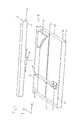
- the support 10 comprises a frame 12 which has a rectangular basic shape.
- L recesses or cuts 16 are provided at regular intervals in the longitudinal direction thereof, which serve as brackets for support 18, wherein the carrier 18 each mounted with their opposite end portions 20 in the recesses 16 and thereby from the frame 12 can be kept.
- FIG. 1 For the sake of clarity, only one carrier 18 is shown. The points in the longitudinal direction L indicate that further such carriers 18 are present.
- one or more cross members 22 extending in the longitudinal direction L can also be provided, on which the carriers 18 also rest.
- the cross beams 22 are connected to the other pair of opposite sides 15 of the frame 12.
- Frame 12, support 18 and cross member 22 are preferably made of steel.
- each support 18 Q support elements 24 are attached at regular intervals in the transverse direction.
- FIG. 1 For the sake of clarity, only two support elements 24 are shown. The points in the transverse direction Q indicate that further support elements 24 may be present. Furthermore, in FIG. 1 a part of a material plate 26 is shown, which rests on the support members 24, which in FIG. 1 but for the sake of clarity is not shown.
- a distance d from each other which is preferably at least 3.5 cm.
- FIG. 1 shows a support 10 which is used in a laser cutting device for cutting metal plates. Shown is also a part 28 of an XY or LQ adjustment of the laser cutting device. As in FIG. 1 is indicated by two arrows, the part 28 is formed movable in the transverse direction Q. At a jet exit portion 30 of the laser cutting device in the longitudinal direction L is arranged movable, which in FIG. 1 again indicated by two arrows. In this way, the beam exit section 30 can be positioned as desired in a plane parallel to the plane defined by the frame 12, that is to say in the longitudinal direction L and in the transverse direction Q. From the beam exit section 30, a laser beam can emerge toward the material plate 26 to cut these.
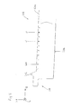
- FIG. 2 Shown is only one of the two end portions 20 of the carrier 18. Both end portions 20 each have a hook 21, with which the carrier 18 can be mounted in recesses 16 of the frame 12 ,
- the Aufsteckverianaschiana 36 allow the attachment of support members 24 on the support 18 by inserting the support members 24 in the Aufsteckverianasch. This will be discussed in more detail below.
- FIG. 3 a support member 24 of the pad 10 according to the invention is shown.
- the support elements 24 are manufactured as separate components, that is, neither with each other nor with the carrier 18 integrally connected.
- the support elements 24 are plate-shaped, wherein the plane of the plate extends in the intended use orientation orthogonal to the transverse direction Q.
- the support member 24 comprises a substantially rectangular portion 24a and one integrally connected thereto triangular portion 24b.
- the tip of the triangular portion 24b is formed flattened to form on a support portion 40 a support surface 24c for material plates 26.
- a plug-in recess 24d is formed in the rectangular section 24a of the support element 24, the dimensions of which are selected such that together with a plug-on depression 36 of the support 18, a stable plug-in connection results.
- the support elements 24 are made of copper or other soft material at least in a portion comprising the support surface 24c for material plates 26, but preferably completely, so that the surfaces of the material plates 26 are not scratched or otherwise damaged. This is particularly advantageous in the case of material plates made of soft metals such as aluminum sheets.
- FIG. 4 shows a part of a second embodiment of a carrier of the pad according to the invention.
- This embodiment corresponds in many parts to the first embodiment of the carrier 18 (see FIG. 2 ).
- analog parts are provided with the same reference numerals as in the FIGS. 1 and 2 , but increased by the number 100.
- the embodiment according to FIG. 4 in the following will be described only insofar as they differ from the embodiment according to FIG. 2 otherwise, reference is hereby made to the description.
- Both end portions 120 extend substantially in the transverse direction (Q) and are insertable into recesses 116 of the frame 112, so that the carrier 118 can be held by the end portions 120 of the frame 112.
- the second embodiment of the carrier 118 differs from the first embodiment of the carrier 18 (see FIG. 2 ) in particular in that an upper boundary surface 118a between all pairs of adjacent Aufsteckveriana 136 is formed free of depressions.
- the carrier 118 thus has no contact with the depressions 32 (FIG. FIG. 2 ) analog recesses.
- the respective end portion 120 in the transverse direction (Q) immediately adjacent, between this end portion 120 and the upper boundary surface 118a a support elevation 142 is provided, in the supporting direction (H) both with respect to the end portions 120 and with respect to upper boundary surface 118a is formed increased.
- the support elevations 142 are provided to support adjacent material plates 26. The upper edge of each support elevation 142 therefore lies in the same plane as the support surfaces 24c of the support elements 24, so that the support elevations 142 and the support elements 24 terminate at the same height in the support direction (H).
Landscapes
- Engineering & Computer Science (AREA)
- Physics & Mathematics (AREA)
- Mechanical Engineering (AREA)
- Optics & Photonics (AREA)
- Plasma & Fusion (AREA)
- Laser Beam Processing (AREA)
Applications Claiming Priority (1)
| Application Number | Priority Date | Filing Date | Title |
|---|---|---|---|
| DE102010028606A DE102010028606A1 (de) | 2010-05-05 | 2010-05-05 | Auflage für eine Werkstoffplatte |
Publications (1)
| Publication Number | Publication Date |
|---|---|
| EP2384846A2 true EP2384846A2 (fr) | 2011-11-09 |
Family
ID=44117622
Family Applications (1)
| Application Number | Title | Priority Date | Filing Date |
|---|---|---|---|
| EP11163892A Withdrawn EP2384846A2 (fr) | 2010-05-05 | 2011-04-27 | Recouvrement pour plaque de matière première |
Country Status (2)
| Country | Link |
|---|---|
| EP (1) | EP2384846A2 (fr) |
| DE (1) | DE102010028606A1 (fr) |
Cited By (1)
| Publication number | Priority date | Publication date | Assignee | Title |
|---|---|---|---|---|
| CN108237302A (zh) * | 2018-01-31 | 2018-07-03 | 中国电子科技集团公司第三十八研究所 | 一种天线阵子的机器人点焊工装及方法 |
Families Citing this family (1)
| Publication number | Priority date | Publication date | Assignee | Title |
|---|---|---|---|---|
| CN103624431B (zh) * | 2012-08-21 | 2015-05-20 | 上海工程技术大学 | 基于t型槽的柔性薄板定位夹具 |
Family Cites Families (3)
| Publication number | Priority date | Publication date | Assignee | Title |
|---|---|---|---|---|
| AT321688B (de) * | 1973-05-23 | 1975-04-10 | Voest Ag | Brennschneidanlage zum Durchtrennen metallischer Werkstücke, insbesondere metallischer Bleche oder Platten |
| DE8622740U1 (de) * | 1986-08-25 | 1986-10-09 | Messer Griesheim Gmbh, 6000 Frankfurt | Schneid- und/oder Schweißtisch |
| DE29923647U1 (de) * | 1999-07-27 | 2001-06-28 | Meiko Maschinenbau GmbH & Co, 77656 Offenburg | Unterlage für Blech |
-
2010
- 2010-05-05 DE DE102010028606A patent/DE102010028606A1/de not_active Withdrawn
-
2011
- 2011-04-27 EP EP11163892A patent/EP2384846A2/fr not_active Withdrawn
Non-Patent Citations (1)
| Title |
|---|
| None |
Cited By (1)
| Publication number | Priority date | Publication date | Assignee | Title |
|---|---|---|---|---|
| CN108237302A (zh) * | 2018-01-31 | 2018-07-03 | 中国电子科技集团公司第三十八研究所 | 一种天线阵子的机器人点焊工装及方法 |
Also Published As
| Publication number | Publication date |
|---|---|
| DE102010028606A1 (de) | 2011-11-10 |
Similar Documents
| Publication | Publication Date | Title |
|---|---|---|
| DE202008012632U1 (de) | Bearbeitungsmaschine für sechsseitige Bearbeitung | |
| EP2134519A2 (fr) | Dispositif de séparation d'un assemblage de tiges en matière plastique à l'aide d'un dispositif à entaille et d'un support portant un dispositif de découpe | |
| DE60114704T2 (de) | Schneidpresse | |
| DE60101431T2 (de) | Positionierungsvorrichtung für keramische Gegenstände | |
| EP0086954A2 (fr) | Outil d'extraction d'un tiroir électronique de son support | |
| DE2822828B2 (de) | Einspann- bzw. Haltevorrichtung für Werkstücke | |
| EP2384846A2 (fr) | Recouvrement pour plaque de matière première | |
| EP3755480B1 (fr) | Installation de fabrication comprenant une unité de changement d'outil et une mâchoire de serrage, ainsi que procédé de changement d'outil | |
| EP3548234B1 (fr) | Couteau long en plusieurs parties | |
| DE102011106469A1 (de) | Werkstückauflageelement und Werkstückauflage daraus | |
| DE68917342T2 (de) | Werkzeuge mit Einsatzzähnen. | |
| DE3104667A1 (de) | Ladeeinrichtung fuer metallrohlinge | |
| DE3203681C2 (de) | Höhenverstelleinrichtung für den Oberstempel eines Anschlagwerkzeuges | |
| DE102011009622A1 (de) | Auflagevorrichtung für eine Laserschneidmaschine | |
| AT505173B1 (de) | Vorrichtung zum bearbeiten von werkstücken | |
| EP3331685A1 (fr) | Dispositif de montage | |
| DE102023114159A1 (de) | Maschine sowie verfahren zum laserschneiden eines plattenförmigen werkstücks | |
| EP4349530B1 (fr) | Dispositif de fixation pour une pièce à usiner | |
| DE102013009806A1 (de) | Ablängwerkzeug | |
| DE102023112767B4 (de) | Tafelschere mit Blechhochhaltevorrichtung | |
| DE102006036193B4 (de) | Vorrichtung und Verfahren zur Montage eines Möbelkorpus | |
| DE69323317T2 (de) | Ausrichten von zu schweissenden blechkanten | |
| DE102022125475B4 (de) | Wasserstrahlschneideverfahren | |
| DE10202204B4 (de) | Vorrichtung und Verfahren zum Bremsen von Werkstückträgern | |
| DE3800100A1 (de) | Fixiervorrichtung fuer den anschlusskontakt einer optischen faser |
Legal Events
| Date | Code | Title | Description |
|---|---|---|---|
| AK | Designated contracting states |
Kind code of ref document: A2 Designated state(s): AL AT BE BG CH CY CZ DE DK EE ES FI FR GB GR HR HU IE IS IT LI LT LU LV MC MK MT NL NO PL PT RO RS SE SI SK SM TR |
|
| AX | Request for extension of the european patent |
Extension state: BA ME |
|
| PUAI | Public reference made under article 153(3) epc to a published international application that has entered the european phase |
Free format text: ORIGINAL CODE: 0009012 |
|
| STAA | Information on the status of an ep patent application or granted ep patent |
Free format text: STATUS: THE APPLICATION IS DEEMED TO BE WITHDRAWN |
|
| 18D | Application deemed to be withdrawn |
Effective date: 20131101 |