EP2384860B1 - Carter pour un outil électrique - Google Patents
Carter pour un outil électrique Download PDFInfo
- Publication number
- EP2384860B1 EP2384860B1 EP11176543.4A EP11176543A EP2384860B1 EP 2384860 B1 EP2384860 B1 EP 2384860B1 EP 11176543 A EP11176543 A EP 11176543A EP 2384860 B1 EP2384860 B1 EP 2384860B1
- Authority
- EP
- European Patent Office
- Prior art keywords
- housing
- power tool
- output shaft
- tool according
- bearing
- Prior art date
- Legal status (The legal status is an assumption and is not a legal conclusion. Google has not performed a legal analysis and makes no representation as to the accuracy of the status listed.)
- Active
Links
Images



Classifications
-
- B—PERFORMING OPERATIONS; TRANSPORTING
- B25—HAND TOOLS; PORTABLE POWER-DRIVEN TOOLS; MANIPULATORS
- B25F—COMBINATION OR MULTI-PURPOSE TOOLS NOT OTHERWISE PROVIDED FOR; DETAILS OR COMPONENTS OF PORTABLE POWER-DRIVEN TOOLS NOT PARTICULARLY RELATED TO THE OPERATIONS PERFORMED AND NOT OTHERWISE PROVIDED FOR
- B25F5/00—Details or components of portable power-driven tools not particularly related to the operations performed and not otherwise provided for
- B25F5/02—Construction of casings, bodies or handles
-
- B—PERFORMING OPERATIONS; TRANSPORTING
- B25—HAND TOOLS; PORTABLE POWER-DRIVEN TOOLS; MANIPULATORS
- B25D—PERCUSSIVE TOOLS
- B25D17/00—Details of, or accessories for, portable power-driven percussive tools
- B25D17/04—Handles; Handle mountings
- B25D17/043—Handles resiliently mounted relative to the hammer housing
-
- B—PERFORMING OPERATIONS; TRANSPORTING
- B25—HAND TOOLS; PORTABLE POWER-DRIVEN TOOLS; MANIPULATORS
- B25F—COMBINATION OR MULTI-PURPOSE TOOLS NOT OTHERWISE PROVIDED FOR; DETAILS OR COMPONENTS OF PORTABLE POWER-DRIVEN TOOLS NOT PARTICULARLY RELATED TO THE OPERATIONS PERFORMED AND NOT OTHERWISE PROVIDED FOR
- B25F5/00—Details or components of portable power-driven tools not particularly related to the operations performed and not otherwise provided for
- B25F5/006—Vibration damping means
-
- B—PERFORMING OPERATIONS; TRANSPORTING
- B25—HAND TOOLS; PORTABLE POWER-DRIVEN TOOLS; MANIPULATORS
- B25D—PERCUSSIVE TOOLS
- B25D2211/00—Details of portable percussive tools with electromotor or other motor drive
- B25D2211/003—Crossed drill and motor spindles
-
- B—PERFORMING OPERATIONS; TRANSPORTING
- B25—HAND TOOLS; PORTABLE POWER-DRIVEN TOOLS; MANIPULATORS
- B25D—PERCUSSIVE TOOLS
- B25D2211/00—Details of portable percussive tools with electromotor or other motor drive
- B25D2211/06—Means for driving the impulse member
- B25D2211/061—Swash-plate actuated impulse-driving mechanisms
-
- B—PERFORMING OPERATIONS; TRANSPORTING
- B25—HAND TOOLS; PORTABLE POWER-DRIVEN TOOLS; MANIPULATORS
- B25D—PERCUSSIVE TOOLS
- B25D2250/00—General details of portable percussive tools; Components used in portable percussive tools
- B25D2250/121—Housing details
Definitions
- the present invention relates to a structure of a housing of a hand-held power tool according to the preamble of claim 1.
- the object can be achieved by a power tool according to claim 1.
- the handle is elastically connected to the power tool body such that it can slide with respect to the power tool body in the axial direction of the tool bit. Therefore, the elastic element can absorb vibration by linear deformation in the axial direction of the tool bit, so that the vibration absorption efficiency of the elastic element can be enhanced. Further, with the construction in which the handle linearly moves with respect to the power tool body, unlike the known rotary handle, the vertical length of the handle is not restricted, so that the size of the handle can be reduced. Further, in this invention, with the construction in which the power tool body has an extending region that extends to a lower region of the handle and receives the sliding movement of the handle, the handle can be supported with stability.
- the handle includes a grip part that extends in a vertical direction transverse to the axial direction of the tool bit, upper and lower arms that extend from extending ends of the grip part in the axial direction of the tool bit, and a transverse part that connects extending ends of the upper and lower arms, so that the handle is configured as a closed-loop frame structure.
- the rigidity of the handle can be increased. Therefore, this structure is effective in preventing damage to the handle in the event of drop of the power tool.
- a side surface region of the handle which is parallel to the axial direction of the tool bit has a sliding surface that can slide with respect to the power tool body.
- the "side surface region of the handle” in this invention represents side surface regions of the arms and the transverse part.
- the sliding surface includes a first sliding region extending in the axial direction of the tool bit, and a second sliding region extending in a vertical direction transverse to the extending direction of the first sliding region.
- the first sliding region is provided on the side surfaces of the arms and the second sliding region is provided on the side surface of the transverse part.
- the hand-held power tool further includes an electric motor that drives the tool bit, and a battery pack from which the electric motor is powered.
- the extending region extending to the lower region of the handle forms a battery pack mounting part to which the battery pack is detachably mounted.
- the extending region extending from the power tool body can be rationally used as a sliding guide region for the handle and as a mount for the battery pack.
- the power tool body and the handle are connected to each other via a guide, and at upper and lower end portions of the handle, the guide allows the handle to slide with respect to the power tool body in the axial direction of the tool bit, while preventing the handle from moving with respect to the power tool body in any direction except the axial direction of the tool bit.
- rattling of the handle can be reduced in the vertical direction as well as in the lateral direction, so that rattling can be further reduced.
- the guide includes a concave groove extending in the axial direction of the tool bit and a projection that is engaged with the concave groove for relative movement, and the projection comprises a metal pin.
- the concave groove is formed of a different material from the metal pin.
- one of the concave groove and the projection is formed on the power tool body side and the other is formed on the handle side.
- at least the side on which the groove is formed may be made of synthetic resin or aluminum alloy.
- the protrusion and the groove which slide with respect to each other are formed of heterogeneous materials so that the sliding ability can be improved.
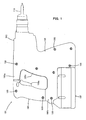
- FIG. 1 shows an entire structure of the hammer drill 101 according to this example
- FIG. 2 is a side view showing an internal structure of the hammer drill 101 by broken line and partly in section. As shown in FIG.
- the hammer drill 101 mainly includes a body 103 that forms an outer shell of the hammer drill 101, a hammer bit 119 detachably coupled to the tip end region of the body 103 via a tool holder 137, a handgrip 109 connected to the body 103 on the side opposite to the hammer bit 119 and designed to be held by a user, and a battery pack 107 attached to the underside of the body 103.
- the body 103, the hammer bit 119 and the handgrip 109 are features that correspond to the "power tool body", the "tool bit” and the "handle", respectively.
- the hammer bit 119 is held by the tool holder 137 such that it is allowed to reciprocate with respect to the tool holder in its axial direction and prevented from rotating with respect to the tool holder in its circumferential direction.
- the side of the hammer bit 119 is taken as the front side and the side of the handgrip 109 as the rear side.
- the body 103 mainly includes a housing 105 that houses an electric motor 111, a motion converting mechanism 113, a striking mechanism 115 and a power transmitting mechanism 117.
- the rotating output of the electric motor 111 is appropriately converted into linear motion via the motion converting mechanism 113 and transmitted to the striking mechanism 115.
- an impact force is generated in the axial direction of the hammer bit 119 via the striking mechanism 115.
- the power transmitting mechanism 117 appropriately reduces the speed of the rotating output of the electric motor 111 and then transmits the rotating output to the hammer bit 119.
- the hammer bit 119 is caused to rotate in the circumferential direction.
- the electric motor 111 is driven when an electric switch 109b is turned on by depressing a trigger 109a on the handgrip 109.
- the electric motor 111 is disposed in a lower region within the housing 105 and arranged such that its axis of rotation extends obliquely with respect to the vertical direction and transversely to the axial direction of the hammer bit 119.
- the motion converting mechanism 113 mainly includes a driving gear 121 that is rotated by the electric motor 111, a driven gear 123 that engages with the driving gear 121 and is rotated in a vertical plane, a rotating element 127 that rotates together with the driven gear 123 via an intermediate shaft 125, a swinging member in the form of a swinging ring 129 that is caused to swing in the axial direction of the hammer bit 119 by rotation of the rotating element 127, and a driving element in the form of a cylindrical piston 141 that is caused to reciprocate by swinging movement of the swinging ring 129.
- the swinging ring 129 is rotatably supported on the rotating element 127 via a bearing.
- the cylindrical piston 141 has a closed end (closed rear end).
- the cylindrical piston 141 is slidably disposed within the cylindrical tool holder 137 that is disposed coaxially with the cylindrical piston 141.
- the cylindrical piston 141 is driven by swinging movement (by its components in the axial direction of the hammer bit 119) of the swinging ring 129, and reciprocates along the tool holder 137.
- the striking element 115 mainly includes a striking element in the form of a striker 143 slidably disposed within the bore of the cylindrical piston 141, and an intermediate element in the form of an impact bolt 145 that is slidably disposed within the tool holder 137 and serves to transmit the kinetic energy of the striker 143 to the hammer bit 119.
- the striker 143 is then driven (linearly moved) by pressure fluctuations of air (the action of an air spring) within an air chamber of the cylindrical piston 141 as a result of the sliding movement of the piston 141.
- the striker 143 then collides with (strikes) the impact bolt 145 which is slidably disposed within the tool holder 137, and transmits the striking force to the hammer bit 119 via the impact bolt 145.
- the cylindrical piston 141, the striker 143 and the impact bolt 145 form a bit striking mechanism.
- the power transmitting mechanism 117 mainly includes a first transmission gear 131 that is caused to rotate in a vertical plane by the electric motor 111 via the intermediate shaft 125, and a second transmission gear 133 that is engaged with the first transmission gear 131 and coaxially mounted on the tool holder 137.
- the rotational driving force of the second transmission gear 133 is transmitted to the tool holder 137 and then to the hammer bit 119 held by the tool holder 137.
- the hammer bit 119 performs a drilling operation on a workpiece (concrete) by a hammering movement in the axial direction and a drilling movement in the circumferential direction.
- the hammer drill 101 can be appropriately switched between a hammering operation mode in which only a striking force in the axial direction is applied to the hammer bit 119, and a hammer drill operation mode in which a striking force in the axial direction and a rotating force in the circumferential direction are applied to the hammer bit 119.
- This construction is not directly related to this invention and therefore will not be described.
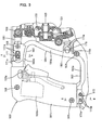
- FIGS. 3 and 4 show the vibration-proof structure of the handgrip 109
- FIGS. 5 and 6 are sectional views taken along line A-A and line B-B in FIG. 3 , respectively.
- the hollow housing 105 forming the body 103 includes right and left housing halves 105L, 105R into which the housing 105 is split in the axial direction of the hammer bit 119.
- FIGS. 3 and 4 show the state in which the housing half 105L on the left side of the hammer drill 101 as viewed from the front is removed.
- a plurality of cylindrical dowels 151 are integrally formed on its edge region on the mating face side (the inner surface side) and protrude in a direction perpendicular to the mating face.
- a plurality of dowel holes 153 are formed to correspond with the dowels 151.
- the dowels 151 are fitted in the dowel holes 153, and in this state, the right and left housing halves 105L, 105R are joined to each other by screws 155 through the dowels.
- the handgrip 109 includes a grip part 161 extending in a vertical direction transverse to the axial direction of the hammer bit 119, upper and lower arms 162, 163 extending from extending ends of the grip part in a horizontal direction transverse to the extending direction of the grip part, and a stay 164 that extends substantially parallel to the grip part 161 and connects the extending ends of the upper and lower arms 162, 163, so that the handgrip 109 is configured as a closed-loop integral frame structure.
- the stay 164 is a feature that corresponds to the "transverse part".
- the handgrip 109 includes right and left handgrip halves 109L, 109R into which the handgrip 109 is split in the axial direction of the hammer bit 119.
- a plurality of cylindrical dowels 167 are integrally formed on its edge region on the mating face side (the inner surface side) and protrude in a direction perpendicular to the mating face.
- a plurality of dowel holes 168 are formed to correspond with the dowels 167.
- the dowels 167 are fitted in the dowel holes 168, and in this state, the right and left handgrip halves 109L, 109R are joined to each other by screws 169 through the dowels.
- a rear region of the housing 105 is generally U-shaped in side view, having an upper extending portion 105a extending to the upper arm 162 of the handgrip 109, a lower extending portion 105b extending to the lower arm 163, and an intermediate portion 105c extending therebetween. Openings are formed in a lower surface and a rear end surface of the upper extending portion 105a, an upper surface of the lower extending portion 105b and a rear surface of the intermediate portion 105c.
- the upper and lower arms 162, 163 and the stay 164 of the handgrip 109 are inserted into the upper extending portion 105a, the lower extending portion 105b and the intermediate portion 105c, respectively, through the openings, and can move in the axial direction of the hammer bit 119.
- the lower extending portion 105b is a feature that corresponds to the "extending region”.
- the battery pack 107 is detachably mounted on the underside of the lower extending portion 105b of the housing 105. Specifically, the lower extending portion 105b also serves as a mount for the battery pack 107.
- the handgrip 109 is held (enclosed) by the generally U-shaped rear region of the housing 105 from laterally outward.
- the handgrip 109 is supported in such a manner as to be movable with respect to the housing 105 in the axial direction of the hammer bit 119.
- the handgrip 109 is connected at the front end to the housing 105 via upper and lower coil springs 181, 183.
- the upper coil spring 181 is elastically disposed between a front end surface of the upper arm 162 and a rear wall surface of an inner housing 185 disposed within the housing 105.
- the lower coil spring 183 is elastically disposed between a front lower portion of the stay 164 and the rear wall surface of the inner housing 185.
- the right and left side surfaces of the upper and lower arms 162, 163 and the right and left side surfaces of the stay 164 in the handgrip 109 have smooth surfaces 162a, 163a, 164a parallel to the axial direction of the hammer bit 119, in part or in entirety.
- the smooth surfaces 162a, 163a of the upper and lower arms 162, 163 extend in the axial direction of the hammer bit 119, and the smooth surface 164a of the stay 164 extends vertically in a direction transverse to the axial direction of the hammer bit 119.
- the smooth surfaces 162a, 163a, 164a are slidably held in contact with opening edges (wall surfaces) 165 (see FIG. 5 ) of the openings of the upper extending portion 105a, the lower extending portion 105b and the intermediate portion lost.
- the opening edges 165 form sliding guide surfaces which slide in surface contact with the smooth surfaces 162a, 163a, 164a.
- the structures of contact between the smooth surfaces 163a, 164a of the lower arm 163 and the stay 164 and the opening edges of the lower extending portion 105b and the intermediate portion 105c, which are not shown, are similarly configured as the structure of contact between the smooth surface 162a of the upper arm 162 and the opening edge 165 of the upper extending portion 105a, which is shown in FIG. 5 .
- the smooth surfaces 162a, 163a, 164a are features that correspond to the "sliding surface”.
- the smooth surfaces 162a, 163a of the upper extending portion 105a and the lower extending portion 105b and the smooth surface 164a of the stay 164 are features that correspond to the "first sliding region.” and the "second sliding region", respectively.
- Slide guides 171, 173, 175 are provided between the upper arm 162 of the handgrip 109 and the upper extending portion 105a of the housing 105, between the lower arm 163 and the lower extending portion 105b and between the stay 164 and the intermediate portion 105c.
- the upper and lower slide guides 171, 173 are features that correspond to the " guide”.
- the upper slide guide 171 includes a slot 171a that is formed generally in the middle of the upper arm 162 in its extending direction, and a protrusion 171b that is formed on the upper extending portion 105a and slidably inserted through the slot 171a.
- the above-described cylindrical dowel 151 formed on the left housing half 105L also serves as the protrusion 171b.
- two dowels 151 are disposed side by side in the axial direction of the hammer bit 119 in such a manner as to serve also as protrusions 171b.
- the slot 171a is formed through the upper arm in the lateral direction (see FIG. 5 ) and has a predetermined length extending in the axial direction of the hammer bit 119 (see FIGS. 3 and 4 ).
- the lower slide guide 173 includes protrusions in the form of two metal pins 173b mounted to a rear end portion (an area of connection with the grip part 161) of the lower arm 163, and concave grooves 173a (shown by two-dot chain line in FIGS. 3 and 4 ) formed in the inner surface of the upper rear-end portion of the lower extending portion 105b (in the inner surfaces of the right and left housing halves 105L, 105R).
- the ends of each of the metal pins 173b are slidably engaged in the concave grooves 173a.
- the two metal pins 173b extend through the lower arm 163 in the lateral direction and are disposed side by side with a predetermined spacing therebetween in the axial direction of the hammer bit 119.
- the extending ends (axial ends) of the metal pins 173b are engaged in the concave grooves 173a.
- the concave grooves 173a have a predetermined length extending in the axial direction of the hammer bit 119.
- the right and left housing halves 105L, 105R having the concave grooves 173a are formed of a different material from the metal pins 173b, for example, a light material such as synthetic resin and aluminum.
- the sliding structure formed of heterogeneous materials can obtain higher sliding ability.
- the intermediate slide guide 175 includes a concave groove 175a and a circular projection 175b (shown by two-dot chain line in the drawings).
- the concave groove 175a is formed in the side surface of the front lower portion of the stay 164 and has a predetermined length extending in the axial direction of the hammer bit 119.
- the circular projection 175b extends inward from the inner surface of the intermediate portion 105c of the housing 105 and is slidably engaged in the concave groove 175a.
- the handgrip 109 is prevented from moving in a vertical direction transverse to the axial direction of the hammer bit 119 with respect to the housing 105, and thus rattling of the handgrip 109 in the vertical direction is reduced.
- FIG. 3 shows an initial state of the handgrip 109 (the state in which the handgrip 109 is mounted to the housing 105). In this state, the handgrip 109 is biased rearward away from the housing 105 by the spring force of the coil springs 181, 183, and at least the protrusions 171b of the upper slide guide 171 are held in contact with the front end of the slot 171a.
- FIG. 4 shows the state in which the handgrip 109 is moved from the initial state to the housing 105 side (forward) as far as possible and the protrusions 171b come in contact with the rear end of the slot 171a (the state of maximum displacement). The maximum amount of relative movement (displacement) of the handgrip 109 is shown by L in FIG. 4 .
- An operation using the hammer drill 101 is performed while the user holds the grip part 161 of the handgrip 109 and applies a forward pressing force to the hammer drill 101.
- the operation is performed in the state in which the protrusions 171b, the metal pins 173b and the circular projection 175b of the upper, lower and intermediate slide guides 171, 173, 175 are placed between the rear and front ends of the slot 171a and the concave grooves 173a, 175a, respectively.
- the handgrip 109 is allowed to move with respect to the housing 105 in the axial direction of the hammer bit 119. Therefore, during operation, vibration which is caused in the housing 105 and transmitted from the housing 105 to the handgrip 109 can be reduced by the coil springs 181, 183.
- the handgrip 109 is elastically connected to the housing 105 by the upper and lower coil springs 181, 183 and mounted to the housing 105 for relative movement in the axial direction of the hammer bit 119. Therefore, the coil springs 181, 183 absorb vibration by linear deformation in the axial direction of the hammer bit, so that the vibration absorption efficiency of the coil springs 181, 183 can be enhanced.
- the vertical length of the handgrip 109 is not restricted, so that the size of the handgrip 109 can be reduced.
- the lower arm 163 of the handgrip 109 can be slidably supported with stability by the lower extending portion 105b of the housing 105, and in addition, the lower extending portion 105b also serves as a mount for the battery pack 107. Therefore, a rational supporting structure can be realized.
- a rear region of the housing 105 is generally U-shaped in side view, having the upper and lower extending portions 105a, 105b extending rearward and the intermediate portion 105c extending therebetween, and the upper and lower arms 162, 163 and the stay 164 of the handgrip 109 are inserted into this generally U-shaped region.
- the relatively wide smooth surfaces 162a, 163a, 164a can be formed on the right and left side surfaces of the arms 162, 163 and the stay 164, so that rattling of the handgrip 109 can be reduced in the lateral direction.
- the upper, lower and intermediate slide guides 171, 173, 175 rattling of the handgrip 109 can be reduced in the vertical direction.
- rattling of the handgrip 109 can be reduced in any direction except the axial direction of the hammer bit 119. Therefore, even if the spring constant of the coil springs 181, 183 is reduced, a sufficient vibration proofing effect can be obtained. Further, such a vibration-proof handgrip 109 feels comfortable to use.
- the hammer drill is described as a representative example , but the present invention can also be applied to a hammer in which the hammer bit 119 performs only the striking movement in the axial direction, or a cutting power tool, such as a reciprocating saw and a jig saw, which performs a cutting operation on a workpiece by reciprocating movement of a blade.
- a battery-powered power tool is described in which the electric motor 111 is powered from the battery pack 107, but the present invention can also be applied to a power tool in which the electric motor 111 is AC powered.
- FIG. 7 is a view showing an entire hammer drill 1 as a representative embodiment.
- a battery 2 is mounted on the underside of the rear (shown on the left in FIG. 7 ) of the hammer drill and a motor 3 is housed in front of the battery 2 such that an output shaft 4 is oriented upward.
- An output section is disposed above the motor 3.
- an intermediate shaft 6 is supported in the longitudinal direction, and a first gear 7 and a swash bearing 8 are fitted on the intermediate shaft 6 one behind the other such that they can individually rotate separately from the intermediate shaft 6.
- a clutch sleeve 9 is arranged between the first gear 7 and the swash bearing 8 such that it can rotate together with the intermediate shaft 6 and can slide in its axial direction.
- a cylindrical tool holder 10 is supported above the intermediate shaft 6 and in parallel therewith, and a second gear 11 that engages with the first gear 7 is integrally fitted on the tool holder 10.
- a piston cylinder 12 is loosely fitted in the tool holder 10 such that it can reciprocate, and a striker 13 is disposed within the piston cylinder 12.
- the rear end of the piston cylinder 12 is connected to an arm 14 of the swash bearing 8.
- an impact bolt 15 is housed within a front portion of the piston cylinder 12 such that it can move in the longitudinal direction.
- a housing of the hammer drill 1 has two parts, or a body housing 20 and a front housing 21.
- the body housing 20 covers all over a rear region of the hammer drill 1 which includes a rear part of the output section 5 and the motor 3, and the front housing 21 covers a front part of the output section 5 in front of the body housing 20. Further, the rear part of the output section 5 is housed within an inner housing 22 installed within the body housing 20.
- the body housing 20 is formed by housing halves in the form of a pair of right and left housings 23, 24.
- Cylindrical bosses 25 each having a threaded bore extend from an inner surface of the left housing 23, and cylindrical bosses 26 each having a through bore extend from an inner surface of the right housing 24.
- the bosses 26 are fitted on the bosses 25 in a coaxially butted manner. Therefore, the right and left housings 23, 24 are assembled into the body housing 20 by inserting screws 27 through each of the bosses 26 from the right housing 24 side and threadably into the associated bosses 25.
- a handle 28 is connected to an upper portion of the rear end of the body housing 20.
- the handle 28 houses a switch 16 which is actuated to drive the motor 3, and the handle 28 has a switch lever 17 which is depressed to turn on the switch 16.
- the inner housing 22 has a box-like shape having an open front end and a closed rear end.
- the inner housing 22 supports a rear end of the intermediate shaft 6 via a ball bearing 29 which is provided within the rear of the inner housing 22.
- an insert hole 30 is formed through the bottom of the inner housing 22, and the output shaft 4 of the motor 3 is inserted into the inner housing 22 through the insert hole 30 such that a ball bearing 31 mounted on the output shaft 4 is fitted in the insert hole 30.
- the inner housing 22 supports the output shaft 4.
- the motor 3 here is arranged within the body housing 20 in a tilted position in which the lower end of the output shaft 4 is located forward of the upper end of the output shaft 4.
- the upper end of the output shat 4 is inserted into the inner housing 22 through the insert hole 30 and engaged with a bevel gear 18, so that rotation of the output shaft 4 can be transmitted to the intermediate shaft 6.
- the bevel gear 18 is fixedly mounted on the rear end portion of the intermediate shaft 6 and located at an input end of the output section 5.
- a sleeve 32 is press-fitted onto the output shaft 4 on the upper end of the ball bearing 31 and a sealing material in the form of an oil seal 33 which is retained within the insert hole 30 is held in sliding contact with the sleeve 32, so that the inner housing 22 is sealed.
- a retaining ring 34 is engaged on the output shaft 4 on the upper end of the sleeve 32.
- a constricted part (groove) 35 is formed in the output shaft 4 at a position corresponding to the opening edge of the insert hole 30, and a stopper ring 36 is fitted in the constricted part 35. The stopper ring 36 is held in contact with an outer end surface of the ball bearing 31 fitted on the output shaft 4.
- a bearing retainer 37 is mounted on the opening edge of the insert hole 30 of the inner housing 22.
- the bearing retainer 37 has a semicircular arc shape to be arranged in contact with half of an circumferential portion of the outer end surface of the ball bearing 31.
- a pair of ring-shaped mounting parts 38 extend radially outward from both end portions (upper and lower portions in the vertical direction as viewed in FIGS. 8(B) and FIG. 8(C) ) of the bearing retainer 37.
- a nut 39 is fixedly mounted on each of the mounting parts 38, and a pair of engaging claws 40 are formed on the bearing retainer 37 between the mounting parts 38 and folded up away from the nut 39 into an L-shape.
- a pair of screw fastening parts 41 are formed on upper and lower portions (as viewed in FIGS. 8 (B) and FIG. 8 (C) ) of the inner housing 22.
- the screw fastening parts 41 each have a thickness large enough to be engaged and locked by the engaging claws 40 and each have a protrusion 42 on its end which faces an end of the other.
- the engaging claws 40 of the bearing retainer 37 When the engaging claws 40 of the bearing retainer 37 are engaged on the screw fastening parts 41, the engaging claws 40 come into contact with the protrusions 42 and thus lock the bearing retainer 37 against vertical movement (as viewed in FIGS. 8 (B) and FIG. 8 (C) ).
- the bearing retainer 37 is positioned in a mounting position in which the centers of the mounting part 38 and the nut 39 are aligned with a through hole (not shown) of the screw fastening part 41.
- a setscrew 43 is inserted through the screw fastening part 41 and the mounting part 38 and screwed into the nut 39.
- the bearing retainer 37 is fastened in contact with the opening edge of the insert hole 30 and the outer end surface of the ball bearing 31, and thus, at the opening edge of the insert hole 30, it prevents the ball bearing 31 from slipping out.
- the sleeve 32 abuts against the ball bearing 31 mounted on the output shaft 4, from above or from the upper end of the output shaft 4, while the bearing retainer 37 also abuts against the ball bearing 31 from below or from the opposite side, so that the output shaft 4 is positioned without rattling in its axial direction.
- cylindrical portions 44 are formed on upper and lower portions of the rear end of the inner housing 22 and each have a positioning hole 45 through which the associated boss 25 of the left housing 23 is inserted in the assembled state of the body housing 20.
- an end surface of the cylindrical portion 44 is held in contact with a rib 46 which extends from the outer periphery of the boss 25 to an inner surface of the left housing 23.
- the right housing 24 is connected to the left housing 23.
- the boss 26 of the right housing 24 comes into contact with the end surface of the cylindrical portion 44, so that the cylindrical portion 44 is centrally positioned in the lateral direction. Specifically, assembling of the body housing 20 by the screws and fixed positioning of the inner housing 22 by the bosses 25, 26 can be simultaneously attained.
- the front end of the inner housing 22 or a protruding part 47 protrudes forward of the front open end of the body housing 20, and an O-ring 49 is fitted in a circumferential groove 48 formed in an outer surface of the protruding part 47.
- the front housing 21 has a rear end opening which conforms to the front end opening of the body housing 20.
- the front housing 21 has a tapered cylindrical shape covering the front portion of the inner housing 22 and the front ends of the tool holder 10 and the intermediate shaft 6.
- a bearing 50 for supporting the tool holder 10 and a ball bearing 51 for supporting a front end of the intermediate shaft 6 are formed on the inside of the front housing 21.
- a screw 53 is inserted through a through hole 52 formed in the rear end of the front housing 21, and then screwed into a threaded hole 54 formed in the front end of each of the left and right housings 23, 24.
- a rib 55 which is formed on the outer surface of the protruding part 47 of the inner housing 22 and extends in the circumferential direction is held between the body housing 20 and the front housing 21, and the O-ring 49 is held in contact with the inner surface of the front housing 21.
- An LED 56 is housed in a front lower portion of the body housing 20 below the motor 3 and oriented forward and obliquely upward such that it can illuminate a region ahead of the bit mounted to the tool holder 10.
- the lower portion of the body housing 20 is configured to correspond to the tilt of the motor 3, or specifically, it has an oblique shape gradually protruding forward toward its lower end.
- the LED 56 is located substantially at the protruding end of the inclined portion of the body housing 20, so that it can effectively illuminate an area to be worked on, from the front end of the body housing 20.
- An air-bleeding hole 57 is formed in the rear end of the inner housing 22 behind the piston cylinder 12 and extends through it in the longitudinal direction as shown in FIG. 13 . Further, a cylindrical portion 58 having a bottom is formed on the rear surface of the inner housing 22 and configured to communicate with the air-bleeding hole 57.
- the cylindrical portion 58 has a longitudinal axis perpendicular to the air-bleeding hole 57 such that it has an open top or end on the right side (as viewed in FIG. 13 ).
- the cylindrical portion 58 is filled with a felt filter 59, and a filter cap 60 is fitted to the open top of the cylindrical portion 58 in such a manner as to prevent the filter 59 from slipping out.
- the filter cap 60 has a cylindrical shape having a bottom and having an open top which faces the filter 59, and an exhaust hole 61 is formed through the center of the closed bottom along its axis of the cylindrical filter cap. Further, a protrusion 62 is formed on the inner surface of the right housing 24 and arranged and configured to extend close to the exhaust hole 61 of the filter cap 60 in the assembled state, in order to prevent removal of the filter cap 60.
- the air is introduced into the cylindrical portion 58 via the air-bleeding hole 57 and discharged through the exhaust hole 61 of the filter cap 60.
- the filter 59 can absorb it.
- the filter cap 60 can hold it back, so that it is prevented from entering the body housing 20 through the exhaust hole 61.
- the exhaust hole 61 is arranged to be oriented in a direction perpendicular to the longitudinally extending air-bleeding hole 57 and to face toward the right housing 24. Therefore, a rational construction can be realized in which, concurrently with the assembling operation of the right housing 24, the protrusion 60 serves to prevent removal of the filter cap 60.
- the motor 3 and the inner housing 22 with the output section 5 housed therein are set on the left housing 23 to which the handle 28 is already connected, and in this state, the right housing 24 is set on the left housing 23 from above and fastened thereto by screws.
- the stopper ring 36, the ball bearing 31, the sleeve 32 and the retaining ring 34 are mounted in respective positions on the output shaft 4.
- the output shaft 4 is inserted into the insert hole 30 to which the oil seal 33 is mounted.
- the upper end of the ball bearing 31 is fitted in an engagement portion 30a which is formed in the insert hole 30 and shaped to fit the ball bearing 31.
- the bearing retainer 37 is fastened to the inner housing 22 by the setscrews 43.
- the front housing 21 is mounted to the front of the body housing 20 in such a manner as to cover it from the front of the output section 5, and fastened by screws. In this manner, as shown in FIG. 7 , assembly of the hammer drill 1 is completed. In this state, the front housing 21 is integrally connected not only to the body housing 20 but to the protruding part 47 of the inner housing 22, so that rigidity of the connection between the body housing 20 and the front housing 21 can be ensured.
- the inner housing 22 provided within the body housing 20 houses part of the output section 5, protrudes forward from the body housing 20 and is fixedly held between the right and left housings 23, 24.
- the front housing 21 is lapped on the protruding part 47 of the inner housing 22 and mounted to the front end of the body housing 20, such that the right and left housings 23, 24 and the front housing 21 can be individually removed.
- rigidity of the connection between the body housing 20 and the front housing 21 can be ensured.
- only the one on the side to be repaired can be removed. Thus, workability relating to repairs or other similar operations can be improved.
- the right and left housings 23, 24 are fastened to each other by screws through the cylindrical bosses 25, 26 which extend from the inner surfaces of the right and left housings 23, 24.
- the bosses 25, 26 are coaxially butted against each other in the assembled state of the right and left housings 23, 24.
- the inner housing 22 has the positioning hole 45 through which the boss 25 is inserted in the assembled state of the body housing 20, so that the inner housing 22 can be fixedly positioned while the right and left housings 23, 24 are fastened to each other by screws.
- the inner housing 22 can be efficiently and accurately mounted in the body housing 20. Therefore, the positioning relationship between the motor 3 and the output section 5 can be stabilized and no problem is caused in transmission of rotation.
- the motor 3 is housed under the inner housing 22 and arranged such that the output shaft 4 is oriented upward and the motor 3 is in a tilted position in which the lower end of the output shaft 4 is located forward of the upper end of the output shaft 4. Further, the upper end of the output shaft 4 is inserted into the inner housing 22 and engaged with the bevel gear 18 at the input end of the output section 5. With this construction, transmission of rotation from the motor 3 to the output section 5 can be ensured.
- the rib 55 which extends in the circumferential direction on the inner housing 22 is held between the body housing 20 and the front housing 21, but, in place of the rib 55, discontinuously extending projections may be used. Further, without using this structure of holding the rib, it may be constructed such that the protruding part of the inner housing is simply held in contact with the inner surface of the front housing.
- the number and configuration of the positioning holes 45 are not limited to those in the above embodiment.
- they may be formed not in the cylindrical portion but in a plate-like part, or depending on the position of the bosses, they may be formed not only on the rear of the inner housing but on the top and the bottom of the inner housing. It is naturally possible to dispense with the positioning holes, and it may be constructed to hold the outer surface of the inner housing by a rib or a recessed seat formed in the inner surface of a housing part
- the hammer drill is not limited to the type in which the motor is housed in a tilted position within the front lower portion of the hammer drill.
- it may be constructed such that the motor is housed not in a tilted position but in a vertical position, or such that the motor is housed behind the output section and oriented forward.
- the motor is located forward of the heavy battery, so that the hammer drill can have a better balance as a whole.
- the handle is located right behind the output section and on the axis of the bit, so that the hammer drill can be pressed forward at a rearward position nearer to the bit on the axis of the bit. Therefore, ease of use can be enhanced.
- crank mechanism may be used in place of the swash bearing, or a fixed cylinder and a piston which reciprocates with respect to the cylinder may be used in place of the piston cylinder.
- an AC power source may be used instead of the DC power source.
- the present invention is not limited to the hammer drill, but it can also be applied to other power tools, such as an electric hammer, an electric drill and an impact driver, in which its housing can be separated into a body housing and a front housing.
- an end of the sleeve 32 press-fitted onto the output shaft 4 is held in contact with one end surface of the ball bearing 31, and the bearing retainer 37 on the inner housing 22 is held in contact with the other end surface of the ball bearing 31.
- the ball bearing 31 is held between the sleeve 32 and the bearing retainer 37, so that the output shaft 4 is positioned in its axial direction.
- the output shaft 4 can be accurately positioned by a simple structure utilizing the existing sleeve 32.
- the output shaft 4 can be held in proper engagement with the bevel gear 18 and thus obtain a favorable durability.
- the bearing retainer 37 having a semicircular arc shape to be arranged in contact with half of a circumferential portion of the outer end surface of the ball bearing 31, the bearing retainer 37 can be formed in a minimum structure required to position the output shaft 4. As a result, the cost of the bearing retainer 37 can be reduced, and the bearing retainer 37 can be easily mounted to the inner housing 22.
- the bearing retainer 37 can be more easily mounted to the inner housing 22.
- the output shaft of the motor is provided with a positioning structure, but, even in a construction, for example, in which an intermediate shaft is supported in parallel to the output shaft between the output shaft and a gear at the input end of the output section such that rotation of the output shaft can be transmitted to the gear at the input end and the intermediate shaft is engaged with the gear, any positioning structure having a bearing retainer can also be used only if a sealing sleeve is provided on the bearing part of the intermediate shaft.
- the bearing retainer may be mounted from the other half side from a direction opposite from the mounting direction in the above-mentioned embodiment, or from above the output shaft.
- the bearing retainer may have a shape other than the semicircular arc shape, such as a C-shape or a ring-like shape. Further, it is not limited to one, but a plurality of bearing retainers having, for example, a short arcuate shape can also be mounted.
- design changes or modifications can also be appropriately made.
- the bearing retainer may be fastened by screws from the side of the opening of the insert hole, or the engaging claws may be dispensed with.
- the bearing is not limited to the ball bearing, but a needle bearing, bearing metal and other types of bearings can also be used according to this invention.
- the power tool to be applied includes not only the hammer drill, but other types of power tools.
Landscapes
- Engineering & Computer Science (AREA)
- Mechanical Engineering (AREA)
- Percussive Tools And Related Accessories (AREA)
- Motor Or Generator Frames (AREA)
Claims (14)
- Outil électrique comprenant :un moteur (3 ; 111) ;un tronçon de sortie (5 ; 113, 115, 117) qui est entraîné par le moteur (3 ; 111);un premier boîtier (20 ; 105) qui reçoit le moteur (3 ; 111);un deuxième boîtier (21) qui reçoit le tronçon de sortie (5 ; 113, 115, 117) au moins en partie, dans lequel le second boîtier (21)) est relié au premier boîtier (20 ; 105);dans lequel le premier boîtier (20 ; 105) est agencé par assemblage de composants de boîtier (23, 24 ; 105L, 105R), et le deuxième boîtier (21) est relié à chacun des composants de boîtier (23, 24 ; 105L, 105R), et dans lequel chacun des composants de boîtier (23, 24 ; 105L, 105R) et le second boîtier (21) sont reliés de manière séparable,caractérisé en ce quechacun des composants de boîtier (23, 24 ; 105L, 105R) a un bossage (25, 26) s'étendant à partir d'une surface intérieure des composants de boîtier (23, 24 ; 105L, 105R), dans lequel le premier boîtier (20) est agencé par couplage de chacun des composants de boîtier (23, 24 ; 105L, 105R) par l'intermédiaire des bossages (25, 26), etun troisième boîtier (22) comporte un trou de prise (45) à travers lequel le bossage (25) est inséré, et dans lequel le troisième boîtier (22) est positionné de manière fixe par mise en prise du bossage (25) dans le trou de prise (45) lorsque les composants de boîtier (23, 24 ; 105L, 105R) sont couplés.
- Outil électrique selon la revendication 1, dans lequel le deuxième boîtier (21) est fixé sur chacun des composants de boîtier (23, 24 ; 105L, 105R) respectivement par l'intermédiaire de vis (53).
- Outil électrique selon les revendications 1 ou 2, dans lequel
le troisième boîtier (22) est serré par les composants de boîtier (23, 24 ; 105L, 105R) et comporte une partie en saillie (47) qui fait saillie à partir du premier boîtier (20 ; 105), et
le deuxième boîtier (21) reçoit la partie en saillie (47). - Outil électrique selon la revendication 3, dans lequel le premier boîtier (20 ; 105) a une première ouverture à travers laquelle la partie en saillie (47) fait saillie, le deuxième boîtier (21) comporte une seconde ouverture correspondant à la première ouverture, et
le deuxième boîtier (21) et la partie en saillie (47) se chevauchent et il est relié au premier boîtier (20 ; 105) de sorte que la seconde ouverture est alignée avec la première ouverture. - Outil électrique selon les revendications 3 ou 4, dans lequel le troisième boîtier (22) est serré par le premier boîtier (20 ; 105) et le deuxième boîtier (21).
- Outil électrique selon l'une quelconque des revendications 1 à 5, dans lequel
le tronçon de sortie (5 ; 113, 115, 117) comprend un arbre (6 ; 125) s'étendant le long d'une direction de saillie d'une partie en saillie (47) du troisième boîtier (22), la partie en saillie (47) fait saillie à partir du premier boîtier (20 ; 105),
le moteur (3) comprend un arbre de sortie (4) s'étendant le long d'une direction longitudinale de l'arbre de sortie (4),
l'arbre de sortie (4) a une extrémité supérieure en prise avec le tronçon de sortie (5 ; 113, 115, 117), et une extrémité inférieure, et
le moteur (3) est agencé de sorte que le moteur (3) est dans une position basculée dans laquelle l'extrémité inférieure de l'arbre de sortie (4) est située à l'avant de l'extrémité supérieure de l'arbre de sortie (4) par rapport à la direction de saillie. - Outil électrique selon l'une quelconque des revendications 1 à 6, dans lequel l'outil électrique est adapté pour entraîner un embout d'outil (119) relié de manière séparable au tronçon de sortie (5 ; 113, 115, 117), linéairement dans une direction prédéterminée, l'outil électrique comprend de plus
une poignée (28 ; 109) reliée au premier boîtier (20 ; 105) à l'opposé de l'embout d'outil (119) par rapport à la direction prédéterminée par l'intermédiaire d'un élément élastique (181, 183) de telle sorte que la poignée (28 ; 109) peut coulisser le long de la direction prédéterminée. - Outil électrique selon la revendication 7, dans lequel la poignée (28 ; 109) s'étend le long d'une direction transversale recoupant la direction prédéterminée, le premier boîtier (20 ; 105) a une zone d'extension (105b) s'étendant sur un côté de la poignée (28 ; 109) par rapport à la direction transversale.
- Outil électrique selon l'une quelconque des revendications 1 à 8, dans lequel
le tronçon de sortie (5 ; 113, 115, 117) est adapté pour convertir la sortie rotative d'un arbre de sortie (4) en un mouvement linéaire et un mouvement de rotation d'un embout d'outil (119) à maintenir dans un porte outil (10), et
l'axe de rotation de l'arbre de sortie (4) s'étend en oblique par rapport à la direction verticale et transversalement par rapport à un axe du mouvement linéaire et de rotation de l'embout d'outil (4). - Outil électrique selon la revendication 9, dans lequel
une extrémité supérieure de l'arbre de sortie (4) est en prise avec un engrenage conique (18 ; 123) pour transmettre la sortie en rotation de l'arbre de sortie (4) à un arbre (6 ; 125), l'engrenage conique (18 ; 123) étant monté sur une partie d'extrémité arrière de l'arbre (6 ; 125) et situé au niveau d'une extrémité d'entrée du tronçon de sortie (5 ; 113, 115, 117). - Outil électrique selon l'une quelconque des revendications 1 à 10, dans lequel
l'outil électrique comprend de plus un troisième boîtier (22) qui est serré par les composants de boîtier (23, 24 ; 105L, 105R), un trou pour élément rapporté (30) étant formé à travers une partie inférieure du troisième boîtier (22), et
le moteur comprend un arbre de sortie (4) inséré dans le troisième boîtier (22) à travers le trou pour élément rapporté (36) de sorte qu'un palier (31) monté sur l'arbre de sortie (4) est agencé dans le trou pour élément rapporté (30) de sorte que le troisième boîtier (22) supporte l'arbre de sortie (4). - Outil électrique selon la revendication 11, dans lequel
un manchon (32) est agencé de manière serrée sur l'arbre de sortie (4) sur une extrémité supérieure du palier (31) et maintenu en contact coulissant avec un matériau d'étanchéité (33) agencé entre l'arbre de sortie (4) et le troisième boîtier (22) de sorte que le troisième boîtier (22) est rendu étanche, et
une extrémité du manchon (32) est maintenue en contact avec une surface d'extrémité du palier (31), et un élément de retenue de palier (37) est monté sur le troisième boîtier (22) et maintenu en contact avec l'autre surface d'extrémité du palier (31), de sorte que le palier (31) est maintenu entre le manchon (32) et l'élément de retenue de palier (37) de sorte que l'arbre de sortie (4) est positionné dans une direction axiale de l'arbre de sortie (4). - Outil électrique selon la revendication 12, dans lequel
l'élément de retenue de palier (37) a une forme d'arc semi-circulaire pour être agencé en contact avec une moitié d'une partie circonférentielle du palier (31). - Outil électrique selon les revendications 12 ou 13, dans lequel
une mâchoire de mise en prise (40) est formée sur l'élément de retenue de palier (37) et la mâchoire de mise en prise (40) est en prise avec une partie de prise formée sur le troisième boîtier (22) et positionne donc l'élément de retenue de palier (37) dans une position de montage sur le troisième boîtier (22).
Applications Claiming Priority (4)
| Application Number | Priority Date | Filing Date | Title |
|---|---|---|---|
| JP2008167791A JP5171432B2 (ja) | 2008-06-26 | 2008-06-26 | 電動工具 |
| JP2008167792A JP5197184B2 (ja) | 2008-06-26 | 2008-06-26 | 回転軸の位置決め構造 |
| JP2008168770A JP5294726B2 (ja) | 2008-06-27 | 2008-06-27 | 手持式作業工具 |
| EP09008268A EP2138278B1 (fr) | 2008-06-26 | 2009-06-24 | Poignée pour un outil électrique |
Related Parent Applications (1)
| Application Number | Title | Priority Date | Filing Date |
|---|---|---|---|
| EP09008268.6 Division | 2009-06-24 |
Publications (2)
| Publication Number | Publication Date |
|---|---|
| EP2384860A1 EP2384860A1 (fr) | 2011-11-09 |
| EP2384860B1 true EP2384860B1 (fr) | 2013-06-19 |
Family
ID=41171115
Family Applications (2)
| Application Number | Title | Priority Date | Filing Date |
|---|---|---|---|
| EP09008268A Active EP2138278B1 (fr) | 2008-06-26 | 2009-06-24 | Poignée pour un outil électrique |
| EP11176543.4A Active EP2384860B1 (fr) | 2008-06-26 | 2009-06-24 | Carter pour un outil électrique |
Family Applications Before (1)
| Application Number | Title | Priority Date | Filing Date |
|---|---|---|---|
| EP09008268A Active EP2138278B1 (fr) | 2008-06-26 | 2009-06-24 | Poignée pour un outil électrique |
Country Status (4)
| Country | Link |
|---|---|
| US (2) | US20090321101A1 (fr) |
| EP (2) | EP2138278B1 (fr) |
| AT (1) | ATE526120T1 (fr) |
| RU (1) | RU2503813C2 (fr) |
Cited By (2)
| Publication number | Priority date | Publication date | Assignee | Title |
|---|---|---|---|---|
| TWI789222B (zh) * | 2022-01-26 | 2023-01-01 | 車王電子股份有限公司 | 具有握把互換結構的衝擊工具 |
| TWI855711B (zh) * | 2021-04-26 | 2024-09-11 | 美商施耐寶公司 | 衝擊錘工具 |
Families Citing this family (44)
| Publication number | Priority date | Publication date | Assignee | Title |
|---|---|---|---|---|
| DE102009027317B4 (de) * | 2009-06-30 | 2019-12-05 | Robert Bosch Gmbh | Werkzeug |
| DE102009054640A1 (de) * | 2009-12-15 | 2011-06-16 | Robert Bosch Gmbh | Handwerkzeugmaschine |
| US8636081B2 (en) | 2011-12-15 | 2014-01-28 | Milwaukee Electric Tool Corporation | Rotary hammer |
| JP5726654B2 (ja) * | 2011-07-01 | 2015-06-03 | 株式会社マキタ | 打撃工具 |
| US8915331B2 (en) * | 2011-09-29 | 2014-12-23 | Lincoln Industrial Corporation | Battery powered, handheld lubrication gun with display |
| JP2013151055A (ja) | 2012-01-26 | 2013-08-08 | Makita Corp | 打撃工具 |
| US9849577B2 (en) | 2012-02-03 | 2017-12-26 | Milwaukee Electric Tool Corporation | Rotary hammer |
| US9308636B2 (en) | 2012-02-03 | 2016-04-12 | Milwaukee Electric Tool Corporation | Rotary hammer with vibration dampening |
| CN103291844A (zh) * | 2012-03-02 | 2013-09-11 | 博世电动工具(中国)有限公司 | 电动工具及其传动装置 |
| EP3189940B1 (fr) * | 2012-12-25 | 2018-01-31 | Makita Corporation | Outil à impact |
| US20150328764A1 (en) | 2013-02-01 | 2015-11-19 | Makita Corporation | Power tool |
| JP6096593B2 (ja) | 2013-05-29 | 2017-03-15 | 株式会社マキタ | 往復動式作業工具 |
| JP6085225B2 (ja) * | 2013-06-27 | 2017-02-22 | 株式会社マキタ | ネジ締め電動工具 |
| EP3022019B2 (fr) * | 2013-07-15 | 2025-08-06 | Milwaukee Electric Tool Corporation | Perceuse à percussion |
| AU2014368261B2 (en) * | 2013-12-20 | 2018-04-19 | Hitachi Koki Co., Ltd. | Power-actuated tool |
| EP2898994A1 (fr) | 2014-01-23 | 2015-07-29 | Black & Decker Inc. | Outil électrique avec une poignée arrière |
| EP2898992B1 (fr) * | 2014-01-23 | 2016-05-04 | Black & Decker Inc. | Outil électrique avec poignée arrière, méthode d'assemblage d'une partie d'une poignée pour un outil électrique et méthode de démontage d'une partie d'une poignée pour un outil électrique |
| EP2898991B1 (fr) * | 2014-01-23 | 2018-12-26 | Black & Decker Inc. | Poignée arrière |
| EP2898993B1 (fr) | 2014-01-23 | 2019-01-30 | Black & Decker Inc. | Outil electrique |
| JP6501414B2 (ja) * | 2014-03-25 | 2019-04-17 | 株式会社マキタ | 打撃工具 |
| JP6348337B2 (ja) * | 2014-05-16 | 2018-06-27 | 株式会社マキタ | 往復動式作業工具 |
| JP6278830B2 (ja) * | 2014-05-16 | 2018-02-14 | 株式会社マキタ | 打撃工具 |
| WO2016076377A1 (fr) * | 2014-11-12 | 2016-05-19 | 株式会社マキタ | Dispositif de frappe |
| DE102015015321B4 (de) | 2014-11-28 | 2024-10-24 | Makita Corporation | Schlagwerkzeug mit Vibrationsdämpfung |
| JP6727828B2 (ja) * | 2016-02-05 | 2020-07-22 | 株式会社マキタ | 動力工具 |
| JP6981744B2 (ja) | 2016-10-07 | 2021-12-17 | 株式会社マキタ | ハンマドリル |
| JP6757226B2 (ja) | 2016-10-07 | 2020-09-16 | 株式会社マキタ | 電動工具 |
| US10875168B2 (en) | 2016-10-07 | 2020-12-29 | Makita Corporation | Power tool |
| JP6863704B2 (ja) * | 2016-10-07 | 2021-04-21 | 株式会社マキタ | 打撃工具 |
| CN109789542B (zh) * | 2016-10-07 | 2023-02-03 | 古斯塔夫.克劳克有限责任公司 | 工具 |
| DE102017123102A1 (de) * | 2016-11-04 | 2018-05-09 | Makita Corporation | Kraftwerkzeug |
| JP7287981B2 (ja) | 2018-05-29 | 2023-06-06 | ローベル バーンバウマシーネン ゲゼルシャフト ミット ベシュレンクテル ハフツング | 軌道のナットおよびねじを締め付けるためおよび緩めるためのインパクトレンチ |
| JP7246202B2 (ja) | 2019-02-19 | 2023-03-27 | 株式会社マキタ | 震動機構付き電動工具 |
| JP7229807B2 (ja) | 2019-02-21 | 2023-02-28 | 株式会社マキタ | 電動工具 |
| US12021437B2 (en) | 2019-06-12 | 2024-06-25 | Milwaukee Electric Tool Corporation | Rotary power tool |
| WO2020250715A1 (fr) * | 2019-06-13 | 2020-12-17 | 工機ホールディングス株式会社 | Machine de travail électrique |
| DE102020206450A1 (de) * | 2020-05-25 | 2021-11-25 | Robert Bosch Gesellschaft mit beschränkter Haftung | Handwerkzeugmaschine |
| EP3922414B1 (fr) | 2020-06-09 | 2025-08-27 | Andreas Stihl AG & Co. KG | Boitier |
| US20220055198A1 (en) * | 2020-08-24 | 2022-02-24 | Makita Corporation | Power tool having hammer mechanism |
| JP7585085B2 (ja) * | 2021-02-22 | 2024-11-18 | 株式会社マキタ | 打撃工具 |
| CN220863918U (zh) * | 2021-08-26 | 2024-04-30 | 创科无线普通合伙 | 具有抗振结构的动力工具 |
| KR102576453B1 (ko) * | 2021-10-01 | 2023-09-12 | 계양전기 주식회사 | 전동공구의 충격완충장치 |
| USD1034128S1 (en) * | 2022-02-07 | 2024-07-09 | Robert Bosch Gmbh | Hammer drill |
| EP4302926B1 (fr) | 2022-06-16 | 2025-08-06 | Milwaukee Electric Tool Corporation | Outil compact à percussion |
Family Cites Families (38)
| Publication number | Priority date | Publication date | Assignee | Title |
|---|---|---|---|---|
| US2299881A (en) * | 1941-04-14 | 1942-10-27 | Max J Demo | Electric drill |
| US2525588A (en) * | 1946-12-12 | 1950-10-10 | Leroy F Cameron | Illuminated electric drill and the like |
| DE3122979A1 (de) * | 1981-06-10 | 1983-01-05 | Hilti AG, 9494 Schaan | Bohr- oder meisselhammer |
| DE3410669A1 (de) * | 1984-03-23 | 1985-10-24 | Metabowerke GmbH & Co, 7440 Nürtingen | Daempfungselement und dessen einbau in ein motorisch angetriebenes handwerkzeug |
| DE3505181A1 (de) * | 1985-02-15 | 1986-08-21 | Hilti Ag, Schaan | Schwingungen erzeugendes handwerkzeug |
| DE3536464A1 (de) * | 1985-10-12 | 1987-04-16 | Licentia Gmbh | Elektrowerkzeug mit in einem kunststoffgehaeuse gelagerten antriebsmotor |
| NL8801466A (nl) * | 1988-06-07 | 1990-01-02 | Emerson Electric Co | Inrichting voor het aandrijven van een boor- en/of slaggereedschap. |
| DE3839207A1 (de) * | 1988-11-19 | 1990-05-23 | Hilti Ag | Tragbares handgeraet mit schlagwerk |
| RU2001723C1 (ru) * | 1991-04-08 | 1993-10-30 | Vejttsel Oleg O | Электрическа дрель |
| JPH0825249A (ja) * | 1994-07-12 | 1996-01-30 | Makita Corp | 振動工具及び防振リング |
| DE19646622B4 (de) * | 1996-11-12 | 2004-07-01 | Wacker Construction Equipment Ag | An einem Handgriff führbares Arbeitsgerät |
| DE19905086A1 (de) * | 1999-01-29 | 2000-08-03 | Black & Decker Inc N D Ges D S | Batteriegetriebenes, handgeführtes Elektrowerkzeug |
| US6805207B2 (en) * | 2001-01-23 | 2004-10-19 | Black & Decker Inc. | Housing with functional overmold |
| DE10145464C2 (de) * | 2001-09-14 | 2003-08-28 | Wacker Construction Equipment | Bohr- und/oder Schlaghammer mit anpressdruckabhängiger Leerlaufsteuerung |
| JP2003211374A (ja) * | 2002-01-21 | 2003-07-29 | Hitachi Koki Co Ltd | 電動工具 |
| US6575590B1 (en) * | 2002-03-01 | 2003-06-10 | Jake Wadsworth | Light system for battery powered drill |
| US6814461B2 (en) * | 2003-03-03 | 2004-11-09 | One World Technologies Limited | Battery-operated power tool with light source |
| GB2402098B (en) * | 2003-05-21 | 2007-10-17 | Black & Decker Inc | Vibration reduction apparatus for power tool and power tool incorporating such apparatus |
| DE10341386A1 (de) * | 2003-09-05 | 2005-04-07 | Hilti Ag | Handgeführtes Arbeitsgerät |
| DE10345133A1 (de) * | 2003-09-29 | 2005-04-21 | Bosch Gmbh Robert | Akkuschrauber |
| JP4290582B2 (ja) | 2004-02-09 | 2009-07-08 | 株式会社マキタ | 往復作動式作業工具 |
| US7604071B2 (en) * | 2004-04-30 | 2009-10-20 | Makita Corporation | Power tool with vibration reducing means |
| DE102004051913A1 (de) * | 2004-08-09 | 2006-02-23 | Robert Bosch Gmbh | Akkuschrauber |
| ATE396838T1 (de) * | 2004-12-23 | 2008-06-15 | Black & Decker Inc | Kraftwerkzeuggehäuse |
| EP1674211A1 (fr) * | 2004-12-23 | 2006-06-28 | BLACK & DECKER INC. | Carter pour un outil motorisé |
| DE102005007547B4 (de) * | 2005-02-18 | 2024-11-07 | Robert Bosch Gmbh | Handwerkzeugmaschine |
| FR2884446B3 (fr) * | 2005-04-18 | 2007-03-02 | Tranmax Machinery Co Ltd | Mecanisme de raccordement pour bloc-batterie et outils electriques |
| DE102006016442A1 (de) * | 2006-04-07 | 2007-10-11 | Robert Bosch Gmbh | Handwerkzeugmaschine mit vibrationsgedämpftem Handgriff |
| DE102006020172A1 (de) * | 2006-05-02 | 2007-11-08 | Robert Bosch Gmbh | Handwerkzeugmaschine |
| US7619387B2 (en) * | 2006-05-08 | 2009-11-17 | Ingersoll-Rand Company | Battery pack attachment arrangement |
| TWI281717B (en) * | 2006-05-17 | 2007-05-21 | Univ Tsinghua | Apparatus for aligning microchips on substrate and method for the same |
| EP1882553B1 (fr) * | 2006-07-26 | 2011-09-21 | Hitachi Koki Co., Ltd. | Outil électrique doté d'une lumière |
| JP5016865B2 (ja) * | 2006-08-04 | 2012-09-05 | 株式会社マキタ | 電動工具および電動工具用プロテクタ |
| US7600885B2 (en) * | 2006-08-16 | 2009-10-13 | Icc Innovative Concepts Corporation | Drill incorporating detachable rechargeable flashlight module |
| DE102006045157B4 (de) * | 2006-09-25 | 2020-06-18 | Robert Bosch Gmbh | Handwerkzeugmaschine |
| DE102006051924A1 (de) * | 2006-11-03 | 2008-05-15 | Robert Bosch Gmbh | Handwerkzeugmaschine mit einem vibrationsgedämpften, mit einem Schalter versehenen Handgriff |
| US7770660B2 (en) * | 2007-11-21 | 2010-08-10 | Black & Decker Inc. | Mid-handle drill construction and assembly process |
| US20100071921A1 (en) * | 2008-09-24 | 2010-03-25 | Icc Innovative Concepts Corporation | Environmentally advantageous electric drill with efficiency promoting charge state indicator |
-
2009
- 2009-06-22 US US12/457,777 patent/US20090321101A1/en not_active Abandoned
- 2009-06-24 EP EP09008268A patent/EP2138278B1/fr active Active
- 2009-06-24 EP EP11176543.4A patent/EP2384860B1/fr active Active
- 2009-06-24 AT AT09008268T patent/ATE526120T1/de not_active IP Right Cessation
- 2009-06-25 RU RU2009124369/03A patent/RU2503813C2/ru active
-
2012
- 2012-12-14 US US13/715,516 patent/US20130098648A1/en not_active Abandoned
Cited By (2)
| Publication number | Priority date | Publication date | Assignee | Title |
|---|---|---|---|---|
| TWI855711B (zh) * | 2021-04-26 | 2024-09-11 | 美商施耐寶公司 | 衝擊錘工具 |
| TWI789222B (zh) * | 2022-01-26 | 2023-01-01 | 車王電子股份有限公司 | 具有握把互換結構的衝擊工具 |
Also Published As
| Publication number | Publication date |
|---|---|
| US20090321101A1 (en) | 2009-12-31 |
| US20130098648A1 (en) | 2013-04-25 |
| EP2138278B1 (fr) | 2011-09-28 |
| RU2503813C2 (ru) | 2014-01-10 |
| EP2138278A1 (fr) | 2009-12-30 |
| ATE526120T1 (de) | 2011-10-15 |
| RU2009124369A (ru) | 2010-12-27 |
| EP2384860A1 (fr) | 2011-11-09 |
Similar Documents
| Publication | Publication Date | Title |
|---|---|---|
| EP2384860B1 (fr) | Carter pour un outil électrique | |
| EP2018939B1 (fr) | Outil électrique avec amortisseur de vibration | |
| EP2808130B1 (fr) | Outil électrique à percussion | |
| EP2000264B1 (fr) | Machine-outil avec réducteur dynamique de vibrations | |
| US9321163B2 (en) | Impact tool | |
| US10843321B2 (en) | Power tool | |
| US8844647B2 (en) | Power tool | |
| JP5294726B2 (ja) | 手持式作業工具 | |
| EP2529892B1 (fr) | Outil motorisé | |
| CN109693211B (zh) | 冲击工具 | |
| US11571796B2 (en) | Rotary hammer | |
| EP2415563B1 (fr) | Outil d'impact | |
| JP4456559B2 (ja) | 作業工具 | |
| JP2006110685A (ja) | 往復作動式作業工具 | |
| CN214055146U (zh) | 电锤 | |
| JP2024030739A (ja) | 打撃工具 | |
| CN114248236A (zh) | 电锤 |
Legal Events
| Date | Code | Title | Description |
|---|---|---|---|
| AC | Divisional application: reference to earlier application |
Ref document number: 2138278 Country of ref document: EP Kind code of ref document: P |
|
| AK | Designated contracting states |
Kind code of ref document: A1 Designated state(s): AT BE BG CH CY CZ DE DK EE ES FI FR GB GR HR HU IE IS IT LI LT LU LV MC MK MT NL NO PL PT RO SE SI SK TR |
|
| PUAI | Public reference made under article 153(3) epc to a published international application that has entered the european phase |
Free format text: ORIGINAL CODE: 0009012 |
|
| 17P | Request for examination filed |
Effective date: 20120425 |
|
| 17Q | First examination report despatched |
Effective date: 20120525 |
|
| GRAP | Despatch of communication of intention to grant a patent |
Free format text: ORIGINAL CODE: EPIDOSNIGR1 |
|
| GRAS | Grant fee paid |
Free format text: ORIGINAL CODE: EPIDOSNIGR3 |
|
| GRAA | (expected) grant |
Free format text: ORIGINAL CODE: 0009210 |
|
| AC | Divisional application: reference to earlier application |
Ref document number: 2138278 Country of ref document: EP Kind code of ref document: P |
|
| AK | Designated contracting states |
Kind code of ref document: B1 Designated state(s): AT BE BG CH CY CZ DE DK EE ES FI FR GB GR HR HU IE IS IT LI LT LU LV MC MK MT NL NO PL PT RO SE SI SK TR |
|
| REG | Reference to a national code |
Ref country code: GB Ref legal event code: FG4D |
|
| REG | Reference to a national code |
Ref country code: CH Ref legal event code: EP |
|
| REG | Reference to a national code |
Ref country code: AT Ref legal event code: REF Ref document number: 617375 Country of ref document: AT Kind code of ref document: T Effective date: 20130715 |
|
| REG | Reference to a national code |
Ref country code: IE Ref legal event code: FG4D |
|
| REG | Reference to a national code |
Ref country code: DE Ref legal event code: R096 Ref document number: 602009016634 Country of ref document: DE Effective date: 20130814 |
|
| PG25 | Lapsed in a contracting state [announced via postgrant information from national office to epo] |
Ref country code: ES Free format text: LAPSE BECAUSE OF FAILURE TO SUBMIT A TRANSLATION OF THE DESCRIPTION OR TO PAY THE FEE WITHIN THE PRESCRIBED TIME-LIMIT Effective date: 20130930 Ref country code: GR Free format text: LAPSE BECAUSE OF FAILURE TO SUBMIT A TRANSLATION OF THE DESCRIPTION OR TO PAY THE FEE WITHIN THE PRESCRIBED TIME-LIMIT Effective date: 20130920 Ref country code: SI Free format text: LAPSE BECAUSE OF FAILURE TO SUBMIT A TRANSLATION OF THE DESCRIPTION OR TO PAY THE FEE WITHIN THE PRESCRIBED TIME-LIMIT Effective date: 20130619 Ref country code: FI Free format text: LAPSE BECAUSE OF FAILURE TO SUBMIT A TRANSLATION OF THE DESCRIPTION OR TO PAY THE FEE WITHIN THE PRESCRIBED TIME-LIMIT Effective date: 20130619 Ref country code: LT Free format text: LAPSE BECAUSE OF FAILURE TO SUBMIT A TRANSLATION OF THE DESCRIPTION OR TO PAY THE FEE WITHIN THE PRESCRIBED TIME-LIMIT Effective date: 20130619 Ref country code: NO Free format text: LAPSE BECAUSE OF FAILURE TO SUBMIT A TRANSLATION OF THE DESCRIPTION OR TO PAY THE FEE WITHIN THE PRESCRIBED TIME-LIMIT Effective date: 20130919 Ref country code: SE Free format text: LAPSE BECAUSE OF FAILURE TO SUBMIT A TRANSLATION OF THE DESCRIPTION OR TO PAY THE FEE WITHIN THE PRESCRIBED TIME-LIMIT Effective date: 20130619 |
|
| REG | Reference to a national code |
Ref country code: AT Ref legal event code: MK05 Ref document number: 617375 Country of ref document: AT Kind code of ref document: T Effective date: 20130619 |
|
| REG | Reference to a national code |
Ref country code: LT Ref legal event code: MG4D |
|
| PG25 | Lapsed in a contracting state [announced via postgrant information from national office to epo] |
Ref country code: BG Free format text: LAPSE BECAUSE OF FAILURE TO SUBMIT A TRANSLATION OF THE DESCRIPTION OR TO PAY THE FEE WITHIN THE PRESCRIBED TIME-LIMIT Effective date: 20130919 Ref country code: HR Free format text: LAPSE BECAUSE OF FAILURE TO SUBMIT A TRANSLATION OF THE DESCRIPTION OR TO PAY THE FEE WITHIN THE PRESCRIBED TIME-LIMIT Effective date: 20130619 |
|
| REG | Reference to a national code |
Ref country code: NL Ref legal event code: VDEP Effective date: 20130619 |
|
| PG25 | Lapsed in a contracting state [announced via postgrant information from national office to epo] |
Ref country code: LV Free format text: LAPSE BECAUSE OF FAILURE TO SUBMIT A TRANSLATION OF THE DESCRIPTION OR TO PAY THE FEE WITHIN THE PRESCRIBED TIME-LIMIT Effective date: 20130619 |
|
| PG25 | Lapsed in a contracting state [announced via postgrant information from national office to epo] |
Ref country code: CY Free format text: LAPSE BECAUSE OF FAILURE TO SUBMIT A TRANSLATION OF THE DESCRIPTION OR TO PAY THE FEE WITHIN THE PRESCRIBED TIME-LIMIT Effective date: 20130731 Ref country code: BE Free format text: LAPSE BECAUSE OF FAILURE TO SUBMIT A TRANSLATION OF THE DESCRIPTION OR TO PAY THE FEE WITHIN THE PRESCRIBED TIME-LIMIT Effective date: 20130619 Ref country code: CZ Free format text: LAPSE BECAUSE OF FAILURE TO SUBMIT A TRANSLATION OF THE DESCRIPTION OR TO PAY THE FEE WITHIN THE PRESCRIBED TIME-LIMIT Effective date: 20130619 Ref country code: EE Free format text: LAPSE BECAUSE OF FAILURE TO SUBMIT A TRANSLATION OF THE DESCRIPTION OR TO PAY THE FEE WITHIN THE PRESCRIBED TIME-LIMIT Effective date: 20130619 Ref country code: PT Free format text: LAPSE BECAUSE OF FAILURE TO SUBMIT A TRANSLATION OF THE DESCRIPTION OR TO PAY THE FEE WITHIN THE PRESCRIBED TIME-LIMIT Effective date: 20131021 Ref country code: SK Free format text: LAPSE BECAUSE OF FAILURE TO SUBMIT A TRANSLATION OF THE DESCRIPTION OR TO PAY THE FEE WITHIN THE PRESCRIBED TIME-LIMIT Effective date: 20130619 Ref country code: IS Free format text: LAPSE BECAUSE OF FAILURE TO SUBMIT A TRANSLATION OF THE DESCRIPTION OR TO PAY THE FEE WITHIN THE PRESCRIBED TIME-LIMIT Effective date: 20131019 Ref country code: AT Free format text: LAPSE BECAUSE OF FAILURE TO SUBMIT A TRANSLATION OF THE DESCRIPTION OR TO PAY THE FEE WITHIN THE PRESCRIBED TIME-LIMIT Effective date: 20130619 |
|
| REG | Reference to a national code |
Ref country code: CH Ref legal event code: PL |
|
| PG25 | Lapsed in a contracting state [announced via postgrant information from national office to epo] |
Ref country code: PL Free format text: LAPSE BECAUSE OF FAILURE TO SUBMIT A TRANSLATION OF THE DESCRIPTION OR TO PAY THE FEE WITHIN THE PRESCRIBED TIME-LIMIT Effective date: 20130619 Ref country code: RO Free format text: LAPSE BECAUSE OF FAILURE TO SUBMIT A TRANSLATION OF THE DESCRIPTION OR TO PAY THE FEE WITHIN THE PRESCRIBED TIME-LIMIT Effective date: 20130619 Ref country code: NL Free format text: LAPSE BECAUSE OF FAILURE TO SUBMIT A TRANSLATION OF THE DESCRIPTION OR TO PAY THE FEE WITHIN THE PRESCRIBED TIME-LIMIT Effective date: 20130619 |
|
| REG | Reference to a national code |
Ref country code: IE Ref legal event code: MM4A |
|
| PG25 | Lapsed in a contracting state [announced via postgrant information from national office to epo] |
Ref country code: CY Free format text: LAPSE BECAUSE OF FAILURE TO SUBMIT A TRANSLATION OF THE DESCRIPTION OR TO PAY THE FEE WITHIN THE PRESCRIBED TIME-LIMIT Effective date: 20130619 Ref country code: MC Free format text: LAPSE BECAUSE OF FAILURE TO SUBMIT A TRANSLATION OF THE DESCRIPTION OR TO PAY THE FEE WITHIN THE PRESCRIBED TIME-LIMIT Effective date: 20130619 |
|
| PLBE | No opposition filed within time limit |
Free format text: ORIGINAL CODE: 0009261 |
|
| STAA | Information on the status of an ep patent application or granted ep patent |
Free format text: STATUS: NO OPPOSITION FILED WITHIN TIME LIMIT |
|
| PG25 | Lapsed in a contracting state [announced via postgrant information from national office to epo] |
Ref country code: CH Free format text: LAPSE BECAUSE OF NON-PAYMENT OF DUE FEES Effective date: 20130630 Ref country code: LI Free format text: LAPSE BECAUSE OF NON-PAYMENT OF DUE FEES Effective date: 20130630 Ref country code: IE Free format text: LAPSE BECAUSE OF NON-PAYMENT OF DUE FEES Effective date: 20130624 Ref country code: DK Free format text: LAPSE BECAUSE OF FAILURE TO SUBMIT A TRANSLATION OF THE DESCRIPTION OR TO PAY THE FEE WITHIN THE PRESCRIBED TIME-LIMIT Effective date: 20130619 |
|
| 26N | No opposition filed |
Effective date: 20140320 |
|
| PG25 | Lapsed in a contracting state [announced via postgrant information from national office to epo] |
Ref country code: IT Free format text: LAPSE BECAUSE OF FAILURE TO SUBMIT A TRANSLATION OF THE DESCRIPTION OR TO PAY THE FEE WITHIN THE PRESCRIBED TIME-LIMIT Effective date: 20130619 |
|
| REG | Reference to a national code |
Ref country code: DE Ref legal event code: R097 Ref document number: 602009016634 Country of ref document: DE Effective date: 20140320 |
|
| PG25 | Lapsed in a contracting state [announced via postgrant information from national office to epo] |
Ref country code: MT Free format text: LAPSE BECAUSE OF FAILURE TO SUBMIT A TRANSLATION OF THE DESCRIPTION OR TO PAY THE FEE WITHIN THE PRESCRIBED TIME-LIMIT Effective date: 20130619 |
|
| PG25 | Lapsed in a contracting state [announced via postgrant information from national office to epo] |
Ref country code: TR Free format text: LAPSE BECAUSE OF FAILURE TO SUBMIT A TRANSLATION OF THE DESCRIPTION OR TO PAY THE FEE WITHIN THE PRESCRIBED TIME-LIMIT Effective date: 20130619 |
|
| PG25 | Lapsed in a contracting state [announced via postgrant information from national office to epo] |
Ref country code: HU Free format text: LAPSE BECAUSE OF FAILURE TO SUBMIT A TRANSLATION OF THE DESCRIPTION OR TO PAY THE FEE WITHIN THE PRESCRIBED TIME-LIMIT; INVALID AB INITIO Effective date: 20090624 Ref country code: MK Free format text: LAPSE BECAUSE OF FAILURE TO SUBMIT A TRANSLATION OF THE DESCRIPTION OR TO PAY THE FEE WITHIN THE PRESCRIBED TIME-LIMIT Effective date: 20130619 Ref country code: LU Free format text: LAPSE BECAUSE OF NON-PAYMENT OF DUE FEES Effective date: 20130624 |
|
| REG | Reference to a national code |
Ref country code: FR Ref legal event code: PLFP Year of fee payment: 8 |
|
| REG | Reference to a national code |
Ref country code: FR Ref legal event code: PLFP Year of fee payment: 9 |
|
| REG | Reference to a national code |
Ref country code: FR Ref legal event code: PLFP Year of fee payment: 10 |
|
| PGFP | Annual fee paid to national office [announced via postgrant information from national office to epo] |
Ref country code: DE Payment date: 20250429 Year of fee payment: 17 |
|
| PGFP | Annual fee paid to national office [announced via postgrant information from national office to epo] |
Ref country code: GB Payment date: 20250501 Year of fee payment: 17 |
|
| PGFP | Annual fee paid to national office [announced via postgrant information from national office to epo] |
Ref country code: FR Payment date: 20250508 Year of fee payment: 17 |