EP2384896A2 - Cartouche d'encre - Google Patents
Cartouche d'encre Download PDFInfo
- Publication number
- EP2384896A2 EP2384896A2 EP11163008A EP11163008A EP2384896A2 EP 2384896 A2 EP2384896 A2 EP 2384896A2 EP 11163008 A EP11163008 A EP 11163008A EP 11163008 A EP11163008 A EP 11163008A EP 2384896 A2 EP2384896 A2 EP 2384896A2
- Authority
- EP
- European Patent Office
- Prior art keywords
- cartridge
- ink
- ink cartridge
- clamping rib
- receptacle
- Prior art date
- Legal status (The legal status is an assumption and is not a legal conclusion. Google has not performed a legal analysis and makes no representation as to the accuracy of the status listed.)
- Granted
Links
- 238000003780 insertion Methods 0.000 claims description 26
- 230000037431 insertion Effects 0.000 claims description 26
- 230000007480 spreading Effects 0.000 claims description 10
- 239000000463 material Substances 0.000 claims description 4
- 229910000639 Spring steel Inorganic materials 0.000 claims description 3
- 239000000976 ink Substances 0.000 description 117
- 239000007788 liquid Substances 0.000 description 5
- 241001417534 Lutjanidae Species 0.000 description 4
- 238000000034 method Methods 0.000 description 4
- 230000008569 process Effects 0.000 description 4
- 230000009471 action Effects 0.000 description 3
- 239000012530 fluid Substances 0.000 description 3
- 230000006870 function Effects 0.000 description 3
- 241000047428 Halter Species 0.000 description 2
- 238000005452 bending Methods 0.000 description 2
- 238000009423 ventilation Methods 0.000 description 2
- 241001295925 Gegenes Species 0.000 description 1
- 238000004873 anchoring Methods 0.000 description 1
- 239000003795 chemical substances by application Substances 0.000 description 1
- 210000000078 claw Anatomy 0.000 description 1
- 239000011248 coating agent Substances 0.000 description 1
- 238000000576 coating method Methods 0.000 description 1
- 238000004891 communication Methods 0.000 description 1
- 238000010276 construction Methods 0.000 description 1
- 238000013500 data storage Methods 0.000 description 1
- 230000001419 dependent effect Effects 0.000 description 1
- 238000013461 design Methods 0.000 description 1
- 238000006073 displacement reaction Methods 0.000 description 1
- 230000000694 effects Effects 0.000 description 1
- 238000002347 injection Methods 0.000 description 1
- 239000007924 injection Substances 0.000 description 1
- 230000007257 malfunction Effects 0.000 description 1
- 238000012986 modification Methods 0.000 description 1
- 230000004048 modification Effects 0.000 description 1
- 238000003825 pressing Methods 0.000 description 1
- 230000000284 resting effect Effects 0.000 description 1
- 238000012549 training Methods 0.000 description 1
Images





Classifications
-
- B—PERFORMING OPERATIONS; TRANSPORTING
- B41—PRINTING; LINING MACHINES; TYPEWRITERS; STAMPS
- B41J—TYPEWRITERS; SELECTIVE PRINTING MECHANISMS, i.e. MECHANISMS PRINTING OTHERWISE THAN FROM A FORME; CORRECTION OF TYPOGRAPHICAL ERRORS
- B41J2/00—Typewriters or selective printing mechanisms characterised by the printing or marking process for which they are designed
- B41J2/005—Typewriters or selective printing mechanisms characterised by the printing or marking process for which they are designed characterised by bringing liquid or particles selectively into contact with a printing material
- B41J2/01—Ink jet
- B41J2/17—Ink jet characterised by ink handling
- B41J2/175—Ink supply systems ; Circuit parts therefor
- B41J2/17503—Ink cartridges
- B41J2/17553—Outer structure
-
- B—PERFORMING OPERATIONS; TRANSPORTING
- B41—PRINTING; LINING MACHINES; TYPEWRITERS; STAMPS
- B41J—TYPEWRITERS; SELECTIVE PRINTING MECHANISMS, i.e. MECHANISMS PRINTING OTHERWISE THAN FROM A FORME; CORRECTION OF TYPOGRAPHICAL ERRORS
- B41J2/00—Typewriters or selective printing mechanisms characterised by the printing or marking process for which they are designed
- B41J2/005—Typewriters or selective printing mechanisms characterised by the printing or marking process for which they are designed characterised by bringing liquid or particles selectively into contact with a printing material
- B41J2/01—Ink jet
- B41J2/17—Ink jet characterised by ink handling
- B41J2/175—Ink supply systems ; Circuit parts therefor
- B41J2/17503—Ink cartridges
- B41J2/1752—Mounting within the printer
Definitions
- the invention relates to an ink cartridge according to the preamble of patent claim 1 for insertion into a cartridge receptacle of an inkjet printer.
- Interchangeable ink cartridges of the aforementioned type are well known and are used to supply inkjet printers with ink.
- the ink cartridge usually includes at least one ink chamber in which liquid ink is stored.
- the chambers of an ink cartridge may be fluid mechanically separated from one another, each having its own ink supply and removal openings, or being in fluid communication with each other, having common ink supply and removal openings.
- Fluid-mechanically separated ink chambers are used in particular in ink cartridges for color inkjet printers for receiving different color inks for use.
- Ink cartridges with a single ink chamber or fluidly interconnected ink chambers are used in both mono and color ink jet printers.
- both types of cartridges may be shared, such as providing a separate black ink cartridge and a separate cartridge having, for example, three chambers one color ink at a time, or by disposing both the black ink and, for example, three different color inks, each in its own color Cartridge are provided to one or more fluid-mechanically connected ink chambers.
- one or more ink cartridges are usually inserted into the printer-side cartridge receptacle, which is provided either along with the printer head or stationary in the housing of the inkjet printer.
- the or each ink removal port, or the or each port of the or each ink chamber is fluid mechanically connected to the corresponding supply port in the cartridge receptacle.
- the or each port of the ink cartridge it is necessary for the or each port of the ink cartridge to be airtightly coupled to the or each supply port of the printer. This is achieved in that the ink cartridge is held in a predetermined, defined mounting position in the cartridge holder and locked in this.
- the object of the invention is to provide an ink cartridge available that can be produced inexpensively and safely used in a cartridge holder while avoiding the above-mentioned disadvantages in a simple and user-friendly way and securely fixed in this and can be easily removed again.
- an ink cartridge for insertion into a cartridge receptacle of an ink jet printer, with a housing in which at least one ink storage chamber and an ink port for connecting the ink storage chamber with a provided at the ink jet printer supply port when inserting the ink cartridge in the cartridge receptacle, wherein the A cartridge in the direction of insertion of the ink cartridge in the front cartridge cartridge, an opposite, in the direction of insertion rear end of the ink cartridge, located cartridge back, two opposite side surfaces and a cartridge underside and a cartridge top, wherein at the rear of the cartridge at least one, preferably two in relation on the underside of the cartridge and cartridge top side vertically spaced, Lateralspreizelement (e) for laterally fixing the ink cartridge in one of the cartridge rear side associated recess of the cartridge receptacle is (are) provided.
- An essential point of the invention is that by the Lateralspreizelement or (e), which (s) is preferably provided on the back of the cartridge, but if desired also on the cartridge front side (are), on the one hand, a problem-free, in particular lateral positioning the ink cartridge is ensured in the cartridge receptacle, since the ink cartridge by the at least one Lateralspreizelement laterally to the boundaries of the recess of the cartridge receptacle rests and in this way causes a correct positioning of the ink cartridge in the cartridge receptacle.
- a preferred embodiment of the invention may be provided on the cartridge rear side, or alternatively on the cartridge front, depending on which variant is preferred, two mutually vertically spaced with respect to cartridge base and cartridge top Lateralsp Sonetti, both in the same way on both sides with their lateral ends the respective ends of these associated recesses of the recess of the cartridge receptacle, whereby a positional fixation of the ink cartridge in the cartridge receptacle is further improved.
- the lateral spreading element (s) is (are) formed as a substantially horizontally extending clamping rib (s) which, for ease of insertion of the cartridge, faces laterally somewhat towards the upper surface of the cartridge.
- the invention provides that the or the Lateralspreizelement (s), in particular the clamping rib (s), is wider (are) than the recess of the cartridge receptacle, so that the or the Lateralspreizelement (s), in particular clamping rib (s) at a Inserting the ink cartridge in the cartridge receptacle in each case comes to rest on the edges of the recess of the cartridge receptacle and positioned in this way, the ink cartridge on the one hand correctly in the cartridge receptacle, and at the same time fixed in a correct operating position in the cartridge receptacle.
- At least one, preferably dimensionally stable, support element is provided on the rear side of the cartridge, which extends from the cartridge bottom in the direction of the cartridge top, wherein the or the support element (s) according to a preferred embodiment arranged symmetrically with respect to the lateral boundaries of the cartridge back is (are). If the or the Lateralspreizelement (s), in particular clamping rib (s) is provided on the front of the cartridge (are), the support member is provided analogously to the cartridge front.
- the support element (s) fulfill in terms of the invention advantageously several functions, it being mentioned in the first place that this support element is so is formed so that a longitudinal, ie in the direction of insertion of the ink cartridge in the cartridge receiving positioning is effected by this support element, since this is so, preferably arcuately designed that the back of the support member extending from the back of the cartridge, or alternatively of the Cartridge front side extends, slides along an insertion opening into the cartridge receptacle and comes to lie substantially centrally or in the case of multiple support elements symmetrically with respect to the lateral boundaries of the recess of the cartridge receptacle when the ink cartridge correctly inserted into the cartridge receptacle and in its final position in the cartridge receptacle is fixed by one or more Lateralsp Shinetti.
- the lateral spreading element (s), in particular the clamping rib (s), is (are) connected to the rear of the cartridge and / or to the support element (s).
- the at least one support element serves to stabilize the Lateralsp Sonide or clamping ribs, which can be mounted laterally on the side of a support member which faces in the direction of the lateral boundary of the recess of the cartridge receptacle.
- At least one guide element can be provided which is connected to the cartridge rear or front side and / or to the support element (s).
- Both the or the Lateralspreizelement (s), in particular clamping rib (s), and / or the at least one guide element has (have), preferably laterally, at least one curvature in the direction of the cartridge top.
- the cartridge both position correctly and securely fix in this correct position, wherein the clamping rib during insertion of the ink cartridge in the cartridge receptacle is elastically deformed to form a tension against the boundary of the recess of the cartridge receptacle and in this way by friction in the recess is fixed in position or clamped.
- the one or more lateral expansion elements (e), in particular clamping rib (s), and / or the at least one guide element in a contact region are arranged with the recess of the cartridge receptacle symmetrical to the or the support element (s).
- a Lateralspreizelement used in the context of this invention, or a clamping rib at least partially may have a harder material than the cartridge receptacle.
- a Lateralspreizelement respectively a clamping rib, for example be made of spring steel, in each case in addition a profiling, in particular a toothing on the Lateralspreizelement or the clamping rib can be provided in a contact area with the recess of the cartridge receptacle.
- the respective ends of the Lateralspreizelements, respectively the clamping rib, also with a non-slip, as required rubbery soft coating, be provided on the wall of the recess of the cartridge receptacle, respectively on arranged thereon guide surfaces in a locked state an optimal fixation the cartridge allows.
- a pulling or pushing device for removing the ink cartridge which is provided for example on the lid or in the upper region of the ink cartridge, for example in the form of a projection or a lever.
- the ink cartridge optionally provided on at least one free end of a clamping rib to provide a pulling or pushing device, with which the standing with the lateral boundary of the recess of the cartridge receptacle in engagement or attack end of the clamping rib something in the direction Lid of the ink cartridge is pulled or pressed to reduce the lateral clamping action of the Lateralsp Sonide or, in particular clamping rib (s), or completely to facilitate removal of, for example, empty or other reasons to remove ink cartridge from the cartridge receptacle ,
- At least one release means is provided on the ink cartridge, by means of which for facilitated removal of the ink cartridge from the cartridge receptacle at least one Lateralspreizeiemente (e) from a locking position can be brought into a release position.
- this release agent according to the invention, a removal of the ink cartridge from the cartridge holder in a simple manner possible, since it means this release means is possible, a splayed Lateralspreizelement which is in clamping or frictional engagement with the wall of the recess of the cartridge receptacle to withdraw from this engagement and in this way allows easy and easy removal of the ink cartridge from the cartridge receptacle.
- the respective Lateralspreizelement, or the respective clamping rib is supported by an actuator or guided by a holder, which is advantageously ensures that the respective Lateralspreizelement or the respective clamping rib is located in any case in a correct position and remains in that, in the case of a movable actuator element or a movable support, the actuator element or holder prevents twisting, bending or otherwise escaping from the correct position necessary for locking and, in the course of inserting the ink cartridge in the cartridge receiving deforming Lateralspreizelement, respectively clamping rib, quasi can go along.
- the actuator element and / or the holder with an actuating element in particular via levers, a linkage or one or more cables or bands, connected, or, preferably integrally formed therewith, wherein the actuator element and / or the holder, for example via a Film hinge is connected to the actuator.
- the actuating element is movable, in particular movably and preferably pivotably arranged about a rotating or tilting axis on the ink cartridge, the actuator element and / or the holder being pressed against the or the lateral spreading element (e ), in particular clamping rib (s) is urged, wherein the or the Lateralspreizelement (s), in particular clamping rib (s) is (are) deformed so that the or the Lateralspreizelement (e), In particular clamping rib (s) in the recess with respect to the cartridge lower and the cartridge top in the vertical direction is free to move (are).
- This embodiment of the invention makes it possible in an advantageous manner, by a simple actuation of the actuating element, namely by, for example pressurized, pivoting of the actuating element to deform the Lateralspreizelement or the clamping rib so that their width extension is less than the distance between the walls of the recess Cartridge receptacle, respectively, the guide surfaces extending along these walls, so that the Lateralspreizelement, or the clamping rib can be quasi unlocked, whereby it is possible to easily remove the cartridge from the cartridge receptacle or to insert the cartridge in the cartridge receptacle, wherein a Relief of the actuating element causes the Lateralspreizelement, or the clamping rib, moves into a locking position and comes with the wall of the recess of the cartridge receptacle in frictional or clamping engagement.
- an actuator with actuator element or holder can thus be considered as an important point of the invention, which bends when operating a federstährome clamping rib such that it is narrower than the parallel guide surfaces of the cartridge receptacle and thereby the clamping action of the clamping rib is completely canceled.
- the clamping rib support can be made together with the actuator or actuator as a one-piece plastic injection molded part, which is particularly cost.
- a retaining cam, retaining claw, retaining notch, etc. may be provided on the cartridge, which / which cooperates with a corresponding holding element, for example a recess in the cartridge receptacle in the printer.
- the cartridge can be positioned on this first side, for example by means of retaining cams and the clamping rib with the actuator on the opposite side are mounted and locked.
- clamping rib is installed on one side and the actuation point of the actuator on the other side.
- the force to be transmitted to the clamping rib can be transmitted by means of levers, linkage, cable or the like.
- Fig. 1 shows an ink cartridge 10 according to the invention with a housing 12, an ink port 16 which is disposed on the cartridge bottom 26.
- the cartridge top 36 is limited by a lid 40.
- On the cartridge rear side 54 is a support member 52 and two, each laterally disposed on the support member 52 clamping ribs 58, which have a slight wing-like curvature in the direction of the cartridge top 36 and are tapered to the outside.
- the support member 52 is centrally located on the back 54 with respect to the lateral boundaries of the cartridge rear 54 and in a vertical orientation. Further, the support member 52 has a back curvature along which the support member 52 upon insertion of the ink cartridge 10 in the cartridge receptacle 56 (in Fig. 1 not shown) can slide.
- a guide element 62 is symmetrically arranged on both sides in a lower region of the support element 52, which extends arcuately starting from the support element 52 in the direction of the upper side 56 of the cartridge.
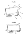
- FIG. 2a an ink cartridge 10 according to the invention is shown, which is inserted into a cartridge receptacle 56.
- the support element 52 can be seen in a lateral view, extending from a lower portion of the cartridge rear side 54 extends arcuately backwards and upwards in the direction of the cover 40, wherein the back of the support member 52, and whose curvature is formed so that during the insertion process of the ink cartridge 10 into the cartridge receptacle 56 causes a correct longitudinal alignment of the ink cartridge 10 in the cartridge receptacle 56.
- a respective lateral clamping rib 58 and a guide element 62 can be seen, wherein both the clamping rib 58 and the guide element 62 are attached both to the support element 52 and to the cartridge rear side 54.
- Fig. 2b shows a side view of an ink cartridge 10 which is inserted into the cartridge receptacle 56 and fixed therein.
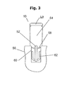
- Fig. 3 shows a rear sectional view of an ink cartridge 10 which is inserted and fixed in a cartridge receptacle 56 in the end position, wherein on a support member 52 on both sides, each symmetrically arranged, outwardly tapering clamping ribs 58, the position of the ink cartridge 10 in the recess 60 of the cartridge receptacle 56 define and fix at the same time.
- two also respectively symmetrically on both sides of the support member 52 arranged guide elements 62 can be seen, which have served during a insertion process of the ink cartridge 10 in the cartridge holder 56 as a guide.
- At least the clamping ribs 58 were curved during the insertion process of the ink cartridge into the cartridge receptacle 56 in the direction of the cover 40, whereby the ink cartridge 10 is fixed in the recess 60 under tension.
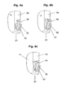
- Fig. 4a shows a cartridge back 54 with a support member 52, clamping ribs 58 and guide elements 62 according to an embodiment according to Fig. 3 but in the non-inserted state of the ink cartridge 10.
- Fig. 4b shows a modification of the positioning and fixing device for an ink cartridge 10 in a cartridge receptacle 56 according to Fig. 4a , in each case two symmetrically mutually arranged clamping ribs 58 are provided in an upper region of the support member 52 on both sides.
- FIG. 4c shows a further variant according to the invention of a positioning and fixing device for an ink cartridge 10 in a cartridge receptacle 56, wherein a continuous clamping rib 58 is inserted into a recess of a support member 52.
- this clamping rib 58 is not tapered to the outside, but has a substantially equal thickness, wherein the respective ends of the clamping rib 58 are provided with a profiling, namely with a toothing.
- Fig. 5 shows a further embodiment of an ink cartridge 10 according to the invention with a housing 12, an ink port 16 which is arranged on the underside 26 of the ink cartridge.
- the cartridge top 36 is limited by a lid 40.
- On the cartridge rear side 54 are a support member 52 and two guide elements 62.
- the guide elements 62 are each side of a holder 30, namely a clamping rib holder, arranged.
- a clamping rib 58, according to Fig. 5 is denoted in the relaxed position by the reference numeral 58a, is guided in the clamping rib holder 30 and projects laterally beyond this clamping rib holder 30 on both sides.
- the clamping rib holder 30 in turn is connected via a film hinge 24 with an actuating element 18, which is formed integrally with the film hinge 24 and the clamping rib holder 30 and forms an actuator 20.
- FIG. 5 an insertion direction 48 for inserting the ink cartridge 10 in a cartridge receptacle (in Fig. 5 not shown) and indicated by an arrow.
- the ink cartridge according to Fig. 5 a ventilation opening 38 and a data memory 34, which are both arranged on the underside 26 of the cartridge 10.
- a guide groove 32 is shown in the lower region of the actuator 20, along which the clamping rib holder 30 slides upon pivoting of the actuating element 18 about a pivot axis 22 due to the film hinge 24 - connection of the actuating element 18 with the clamping rib holder 30,
- FIG. 10 is a rear sectional view of an ink cartridge 10 according to the embodiment of FIG Fig. 5 which is to be inserted into a cartridge receptacle 56 and fixed in this.
- the support member 52 which is disposed on both sides of the support member 52, and arranged on the cartridge rear side 54 actuator 20 which has an actuator 21, which in turn laterally supports the clamping rib 58, with a solid line guide is shown in relaxed state by the reference numeral 58a.
- the reference numeral 58b denotes the state of the clamping rib 58 in a middle position in which the clamping rib 58 is clamped on both sides on the guide surfaces 42, which are designated to distinguish the two clamping sides with the respective reference numerals 42a and 42b.
- the clamping rib 58 has the guide width 44, which are defined and bounded by the guide surfaces 42a and 42b.
- the reference numeral 58 c denotes a tensioned state of the clamping rib 58, which allows removal of the ink cartridge 10 from the cartridge receptacle 56.
- This Klemmrippenschreib 58c is achieved in that Fig. 5 Pressure on the actuating element 18 is applied, so that the cartridge top side 36 associated upper end of the actuating element 18 is pressed in the direction of the cartridge rear side 54, wherein the actuating element 18 is tilted about the rotation axis 22, which causes the clamping rib holder 30, which over the Film hinge 24 is connected to the actuator 18 is pulled upward, the actuator member 21 abuts from below against the clamping rib sides 58 and this pushes up, so world, until the width extension of the clamping rib 58 between the guide surfaces 42 a and 42 b is smaller as the guide width 44.
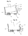
- FIGS. 7a to 7c show an ink cartridge according to the invention according to the in Fig. 5 illustrated embodiment during a Einsetzvorgangs, but not yet in the inserted state ( Fig. 7a ), when inserted ( Fig. 7b ) and in a state suitable for removing the ink cartridge 10 from the cartridge receptacle 56 ( Fig. 7c ).
- the insertion of the ink cartridge 10 in the cartridge receptacle 56 is carried out according to Fig. 7a such that the ink cartridge 10 is first inserted with a retaining cam 46 into a corresponding recess of the cartridge receptacle, whereby the ink port 16 is correctly positioned.
- the ink cartridge is tiltingly lowered with the retaining cam 46 as a fulcrum in the cartridge receptacle 56, wherein the clamping rib 58 is in the relaxed position 58a.
- the actuator 20 When the clamping rib 58 is in the relaxed clamping rib position 58a, the actuator 20 is in a relaxed position, with the actuator element 21 and the clamping rib holder 30 in the lowest position and the lid 40 associated upper end of the actuating element 18 in the direction of the farthest cartridge rear position 54 is located.
- the clamping rib 58 Upon further lowering of the ink cartridge 10 along the direction of insertion 48 into the cartridge receptacle 56, the clamping rib 58, which is in the relaxed position 58a, comes into contact with the guide surfaces 42 of the cartridge receptacle 56, as shown in FIG Fig. 7b is shown, a deformation of the Clamping rib 58 takes place in a locking position 58b of the clamping rib 58.
- Fig. 7c the position of the actuating element 18 is shown, in which a deformation of the clamping rib 58 is achieved, in which the width extent of the clamping rib is smaller than the guide width 44, as in Fig. 6 is shown, so that the ink cartridge 10 according to the invention is ready for removal from the cartridge receptacle 56.
- the clamping rib 58 is in the position 58c, which also Fig. 6 can be removed and in which the clamping rib 58 is maximally deformed by the actuator element 21, respectively the clamping rib holder 30 and has a minimum width extension.
- Fig. 8 shows a further embodiment of the invention, wherein an ink cartridge 10 at its front, the ink port 16 facing upper portion has an actuating element 18 with which a tilting rib about a rotational axis 22, a clamping rib can be brought from a relaxed position via a locking position in a cocked position ,
- the gist of the invention is that, in this way, the ink cartridge can be inserted into the holder without a disadvantageous elastic engaging portion, completely omitting the disadvantageous features of the snapper.
- the embodiments of the invention are much easier to handle and accidental jamming or jamming is avoided.
Landscapes
- Ink Jet (AREA)
Applications Claiming Priority (2)
| Application Number | Priority Date | Filing Date | Title |
|---|---|---|---|
| DE102010016776 | 2010-05-04 | ||
| DE201010016959 DE102010016959A1 (de) | 2010-05-04 | 2010-05-14 | Tintenpatrone |
Publications (3)
| Publication Number | Publication Date |
|---|---|
| EP2384896A2 true EP2384896A2 (fr) | 2011-11-09 |
| EP2384896A3 EP2384896A3 (fr) | 2012-06-20 |
| EP2384896B1 EP2384896B1 (fr) | 2013-09-04 |
Family
ID=44117528
Family Applications (1)
| Application Number | Title | Priority Date | Filing Date |
|---|---|---|---|
| EP20110163008 Not-in-force EP2384896B1 (fr) | 2010-05-04 | 2011-04-19 | Cartouche d'encre |
Country Status (2)
| Country | Link |
|---|---|
| EP (1) | EP2384896B1 (fr) |
| DE (1) | DE102010016959A1 (fr) |
Cited By (1)
| Publication number | Priority date | Publication date | Assignee | Title |
|---|---|---|---|---|
| WO2014160219A1 (fr) * | 2013-03-14 | 2014-10-02 | Fujifilm Dimatix, Inc. | Montage de module d'éjection de fluide |
Citations (1)
| Publication number | Priority date | Publication date | Assignee | Title |
|---|---|---|---|---|
| EP0879703A2 (fr) | 1994-08-24 | 1998-11-25 | Canon Kabushiki Kaisha | Réservoir d'encre pour imprimante par jet d'encre, support pour le réservoir, chariot pour le support et imprimante par jet d'encre |
Family Cites Families (3)
| Publication number | Priority date | Publication date | Assignee | Title |
|---|---|---|---|---|
| US5825387A (en) * | 1995-04-27 | 1998-10-20 | Hewlett-Packard Company | Ink supply for an ink-jet printer |
| CA2379725C (fr) * | 2001-04-03 | 2007-06-12 | Seiko Epson Corporation | Cartouche a encre |
| ATE381992T1 (de) * | 2002-11-26 | 2008-01-15 | Seiko Epson Corp | Tintenpatrone |
-
2010
- 2010-05-14 DE DE201010016959 patent/DE102010016959A1/de not_active Withdrawn
-
2011
- 2011-04-19 EP EP20110163008 patent/EP2384896B1/fr not_active Not-in-force
Patent Citations (1)
| Publication number | Priority date | Publication date | Assignee | Title |
|---|---|---|---|---|
| EP0879703A2 (fr) | 1994-08-24 | 1998-11-25 | Canon Kabushiki Kaisha | Réservoir d'encre pour imprimante par jet d'encre, support pour le réservoir, chariot pour le support et imprimante par jet d'encre |
Cited By (8)
| Publication number | Priority date | Publication date | Assignee | Title |
|---|---|---|---|---|
| WO2014160219A1 (fr) * | 2013-03-14 | 2014-10-02 | Fujifilm Dimatix, Inc. | Montage de module d'éjection de fluide |
| CN105050815A (zh) * | 2013-03-14 | 2015-11-11 | 富士胶卷迪马蒂克斯股份有限公司 | 流体喷射模块安装 |
| JP2016515958A (ja) * | 2013-03-14 | 2016-06-02 | フジフィルム ディマティックス, インコーポレイテッド | 流体吐出モジュール装着 |
| US9358818B2 (en) | 2013-03-14 | 2016-06-07 | Fujifilm Dimatix, Inc. | Fluid ejection module mounting |
| US9566810B2 (en) | 2013-03-14 | 2017-02-14 | Fujifilm Dimatix, Inc. | Fluid ejection module mounting aligning method |
| CN105050815B (zh) * | 2013-03-14 | 2017-09-05 | 富士胶卷迪马蒂克斯股份有限公司 | 流体喷射模块安装 |
| US10308054B2 (en) | 2013-03-14 | 2019-06-04 | Fujifilm Dimatix, Inc. | Fluid ejection module mounting |
| JP2019147390A (ja) * | 2013-03-14 | 2019-09-05 | フジフィルム ディマティックス, インコーポレイテッド | 流体吐出モジュール装着 |
Also Published As
| Publication number | Publication date |
|---|---|
| EP2384896B1 (fr) | 2013-09-04 |
| EP2384896A3 (fr) | 2012-06-20 |
| DE102010016959A1 (de) | 2011-12-01 |
Similar Documents
| Publication | Publication Date | Title |
|---|---|---|
| EP2591919B1 (fr) | Tampon | |
| EP1032316B1 (fr) | Appareil pour la pose d'agrafes | |
| DE69121189T2 (de) | Chirurgische Klammervorrichtung mit Verriegelungsmechanismus | |
| DE2166787C3 (de) | Messerscheide mit Schärfvorrichtung | |
| DE60122388T2 (de) | Schraubendreher mit mehreren bits | |
| EP2056416B1 (fr) | Pince à dénuder | |
| DE202011050828U1 (de) | Verstellbare Armlehne eines Stuhls | |
| EP0615787A1 (fr) | Distributeur manuel pour cartouche double | |
| DE2739809A1 (de) | Chirurgisches klammerwerkzeug | |
| EP1671761A1 (fr) | Rasoir mécanique comprenant une cartouche amovible | |
| EP3973130A1 (fr) | Ferrure pour meuble | |
| DE19725863C2 (de) | Betätigungseinrichtung | |
| DE10320225A1 (de) | Mehrweg-Betätigungsvorrichtung für eine sterile Spritze | |
| EP2384896B1 (fr) | Cartouche d'encre | |
| CH688023A5 (de) | Bindungseinrichtung zwischen einem Schuh und einem Sportgeraet | |
| AT522962B1 (de) | Magazin-Ladehilfe | |
| DE3629111C2 (de) | Heftmaschine des Kassettentyps | |
| DE3139694C2 (de) | Rasierklingeneinheit | |
| DE2511845C2 (de) | Dampfdruckkochtopf mit Bajonettverschluß | |
| DE2922944C2 (de) | Stehbildkamera mit einem in das Kameragehäuse einschiebbaren Objektivtubus | |
| DE19500572A1 (de) | Verstelleinrichtung für Sitz- oder Schlafmöbel | |
| DE3102097A1 (de) | "heftmaschine" | |
| EP2719507A2 (fr) | Couteau, notamment couteau de sécurité | |
| DE69513562T2 (de) | Lastkopf für Wagenheber | |
| DE102004011054B4 (de) | Ratschenartige Verstellvorrichtung |
Legal Events
| Date | Code | Title | Description |
|---|---|---|---|
| AK | Designated contracting states |
Kind code of ref document: A2 Designated state(s): AL AT BE BG CH CY CZ DE DK EE ES FI FR GB GR HR HU IE IS IT LI LT LU LV MC MK MT NL NO PL PT RO RS SE SI SK SM TR |
|
| AX | Request for extension of the european patent |
Extension state: BA ME |
|
| PUAI | Public reference made under article 153(3) epc to a published international application that has entered the european phase |
Free format text: ORIGINAL CODE: 0009012 |
|
| RAP1 | Party data changed (applicant data changed or rights of an application transferred) |
Owner name: PELIKAN HARDCOPY PRODUCTION AG |
|
| PUAL | Search report despatched |
Free format text: ORIGINAL CODE: 0009013 |
|
| AK | Designated contracting states |
Kind code of ref document: A3 Designated state(s): AL AT BE BG CH CY CZ DE DK EE ES FI FR GB GR HR HU IE IS IT LI LT LU LV MC MK MT NL NO PL PT RO RS SE SI SK SM TR |
|
| AX | Request for extension of the european patent |
Extension state: BA ME |
|
| RIC1 | Information provided on ipc code assigned before grant |
Ipc: B41J 2/175 20060101AFI20120514BHEP |
|
| 17P | Request for examination filed |
Effective date: 20121211 |
|
| GRAP | Despatch of communication of intention to grant a patent |
Free format text: ORIGINAL CODE: EPIDOSNIGR1 |
|
| INTG | Intention to grant announced |
Effective date: 20130410 |
|
| GRAS | Grant fee paid |
Free format text: ORIGINAL CODE: EPIDOSNIGR3 |
|
| GRAA | (expected) grant |
Free format text: ORIGINAL CODE: 0009210 |
|
| AK | Designated contracting states |
Kind code of ref document: B1 Designated state(s): AL AT BE BG CH CY CZ DE DK EE ES FI FR GB GR HR HU IE IS IT LI LT LU LV MC MK MT NL NO PL PT RO RS SE SI SK SM TR |
|
| REG | Reference to a national code |
Ref country code: GB Ref legal event code: FG4D Free format text: NOT ENGLISH |
|
| REG | Reference to a national code |
Ref country code: CH Ref legal event code: EP |
|
| REG | Reference to a national code |
Ref country code: AT Ref legal event code: REF Ref document number: 630251 Country of ref document: AT Kind code of ref document: T Effective date: 20130915 |
|
| REG | Reference to a national code |
Ref country code: IE Ref legal event code: FG4D Free format text: LANGUAGE OF EP DOCUMENT: GERMAN |
|
| REG | Reference to a national code |
Ref country code: DE Ref legal event code: R096 Ref document number: 502011001282 Country of ref document: DE Effective date: 20131031 |
|
| REG | Reference to a national code |
Ref country code: NL Ref legal event code: VDEP Effective date: 20130904 |
|
| PG25 | Lapsed in a contracting state [announced via postgrant information from national office to epo] |
Ref country code: LT Free format text: LAPSE BECAUSE OF FAILURE TO SUBMIT A TRANSLATION OF THE DESCRIPTION OR TO PAY THE FEE WITHIN THE PRESCRIBED TIME-LIMIT Effective date: 20130904 Ref country code: HR Free format text: LAPSE BECAUSE OF FAILURE TO SUBMIT A TRANSLATION OF THE DESCRIPTION OR TO PAY THE FEE WITHIN THE PRESCRIBED TIME-LIMIT Effective date: 20130904 Ref country code: SE Free format text: LAPSE BECAUSE OF FAILURE TO SUBMIT A TRANSLATION OF THE DESCRIPTION OR TO PAY THE FEE WITHIN THE PRESCRIBED TIME-LIMIT Effective date: 20130904 Ref country code: CY Free format text: LAPSE BECAUSE OF FAILURE TO SUBMIT A TRANSLATION OF THE DESCRIPTION OR TO PAY THE FEE WITHIN THE PRESCRIBED TIME-LIMIT Effective date: 20130731 Ref country code: NO Free format text: LAPSE BECAUSE OF FAILURE TO SUBMIT A TRANSLATION OF THE DESCRIPTION OR TO PAY THE FEE WITHIN THE PRESCRIBED TIME-LIMIT Effective date: 20131204 |
|
| REG | Reference to a national code |
Ref country code: NL Ref legal event code: VDEP Effective date: 20130904 |
|
| REG | Reference to a national code |
Ref country code: LT Ref legal event code: MG4D |
|
| PG25 | Lapsed in a contracting state [announced via postgrant information from national office to epo] |
Ref country code: SI Free format text: LAPSE BECAUSE OF FAILURE TO SUBMIT A TRANSLATION OF THE DESCRIPTION OR TO PAY THE FEE WITHIN THE PRESCRIBED TIME-LIMIT Effective date: 20130904 Ref country code: GR Free format text: LAPSE BECAUSE OF FAILURE TO SUBMIT A TRANSLATION OF THE DESCRIPTION OR TO PAY THE FEE WITHIN THE PRESCRIBED TIME-LIMIT Effective date: 20131205 Ref country code: LV Free format text: LAPSE BECAUSE OF FAILURE TO SUBMIT A TRANSLATION OF THE DESCRIPTION OR TO PAY THE FEE WITHIN THE PRESCRIBED TIME-LIMIT Effective date: 20130904 Ref country code: PL Free format text: LAPSE BECAUSE OF FAILURE TO SUBMIT A TRANSLATION OF THE DESCRIPTION OR TO PAY THE FEE WITHIN THE PRESCRIBED TIME-LIMIT Effective date: 20130904 Ref country code: FI Free format text: LAPSE BECAUSE OF FAILURE TO SUBMIT A TRANSLATION OF THE DESCRIPTION OR TO PAY THE FEE WITHIN THE PRESCRIBED TIME-LIMIT Effective date: 20130904 |
|
| PG25 | Lapsed in a contracting state [announced via postgrant information from national office to epo] |
Ref country code: CY Free format text: LAPSE BECAUSE OF FAILURE TO SUBMIT A TRANSLATION OF THE DESCRIPTION OR TO PAY THE FEE WITHIN THE PRESCRIBED TIME-LIMIT Effective date: 20130904 |
|
| PG25 | Lapsed in a contracting state [announced via postgrant information from national office to epo] |
Ref country code: CZ Free format text: LAPSE BECAUSE OF FAILURE TO SUBMIT A TRANSLATION OF THE DESCRIPTION OR TO PAY THE FEE WITHIN THE PRESCRIBED TIME-LIMIT Effective date: 20130904 Ref country code: SK Free format text: LAPSE BECAUSE OF FAILURE TO SUBMIT A TRANSLATION OF THE DESCRIPTION OR TO PAY THE FEE WITHIN THE PRESCRIBED TIME-LIMIT Effective date: 20130904 Ref country code: IS Free format text: LAPSE BECAUSE OF FAILURE TO SUBMIT A TRANSLATION OF THE DESCRIPTION OR TO PAY THE FEE WITHIN THE PRESCRIBED TIME-LIMIT Effective date: 20140104 Ref country code: EE Free format text: LAPSE BECAUSE OF FAILURE TO SUBMIT A TRANSLATION OF THE DESCRIPTION OR TO PAY THE FEE WITHIN THE PRESCRIBED TIME-LIMIT Effective date: 20130904 Ref country code: NL Free format text: LAPSE BECAUSE OF FAILURE TO SUBMIT A TRANSLATION OF THE DESCRIPTION OR TO PAY THE FEE WITHIN THE PRESCRIBED TIME-LIMIT Effective date: 20130904 Ref country code: RO Free format text: LAPSE BECAUSE OF FAILURE TO SUBMIT A TRANSLATION OF THE DESCRIPTION OR TO PAY THE FEE WITHIN THE PRESCRIBED TIME-LIMIT Effective date: 20130904 |
|
| RAP2 | Party data changed (patent owner data changed or rights of a patent transferred) |
Owner name: PELIKAN HARDCOPY PRODUCTION AG |
|
| PG25 | Lapsed in a contracting state [announced via postgrant information from national office to epo] |
Ref country code: ES Free format text: LAPSE BECAUSE OF FAILURE TO SUBMIT A TRANSLATION OF THE DESCRIPTION OR TO PAY THE FEE WITHIN THE PRESCRIBED TIME-LIMIT Effective date: 20130904 |
|
| REG | Reference to a national code |
Ref country code: DE Ref legal event code: R097 Ref document number: 502011001282 Country of ref document: DE |
|
| PG25 | Lapsed in a contracting state [announced via postgrant information from national office to epo] |
Ref country code: PT Free format text: LAPSE BECAUSE OF FAILURE TO SUBMIT A TRANSLATION OF THE DESCRIPTION OR TO PAY THE FEE WITHIN THE PRESCRIBED TIME-LIMIT Effective date: 20140106 |
|
| PLBE | No opposition filed within time limit |
Free format text: ORIGINAL CODE: 0009261 |
|
| STAA | Information on the status of an ep patent application or granted ep patent |
Free format text: STATUS: NO OPPOSITION FILED WITHIN TIME LIMIT |
|
| 26N | No opposition filed |
Effective date: 20140605 |
|
| PG25 | Lapsed in a contracting state [announced via postgrant information from national office to epo] |
Ref country code: IT Free format text: LAPSE BECAUSE OF FAILURE TO SUBMIT A TRANSLATION OF THE DESCRIPTION OR TO PAY THE FEE WITHIN THE PRESCRIBED TIME-LIMIT Effective date: 20130904 |
|
| REG | Reference to a national code |
Ref country code: DE Ref legal event code: R097 Ref document number: 502011001282 Country of ref document: DE Effective date: 20140605 |
|
| PG25 | Lapsed in a contracting state [announced via postgrant information from national office to epo] |
Ref country code: DK Free format text: LAPSE BECAUSE OF FAILURE TO SUBMIT A TRANSLATION OF THE DESCRIPTION OR TO PAY THE FEE WITHIN THE PRESCRIBED TIME-LIMIT Effective date: 20130904 |
|
| PG25 | Lapsed in a contracting state [announced via postgrant information from national office to epo] |
Ref country code: LU Free format text: LAPSE BECAUSE OF FAILURE TO SUBMIT A TRANSLATION OF THE DESCRIPTION OR TO PAY THE FEE WITHIN THE PRESCRIBED TIME-LIMIT Effective date: 20140419 Ref country code: MC Free format text: LAPSE BECAUSE OF FAILURE TO SUBMIT A TRANSLATION OF THE DESCRIPTION OR TO PAY THE FEE WITHIN THE PRESCRIBED TIME-LIMIT Effective date: 20130904 |
|
| REG | Reference to a national code |
Ref country code: CH Ref legal event code: PL |
|
| REG | Reference to a national code |
Ref country code: FR Ref legal event code: ST Effective date: 20141231 |
|
| REG | Reference to a national code |
Ref country code: IE Ref legal event code: MM4A |
|
| PG25 | Lapsed in a contracting state [announced via postgrant information from national office to epo] |
Ref country code: CH Free format text: LAPSE BECAUSE OF NON-PAYMENT OF DUE FEES Effective date: 20140430 Ref country code: LI Free format text: LAPSE BECAUSE OF NON-PAYMENT OF DUE FEES Effective date: 20140430 |
|
| PG25 | Lapsed in a contracting state [announced via postgrant information from national office to epo] |
Ref country code: FR Free format text: LAPSE BECAUSE OF NON-PAYMENT OF DUE FEES Effective date: 20140430 |
|
| PG25 | Lapsed in a contracting state [announced via postgrant information from national office to epo] |
Ref country code: IE Free format text: LAPSE BECAUSE OF NON-PAYMENT OF DUE FEES Effective date: 20140419 |
|
| GBPC | Gb: european patent ceased through non-payment of renewal fee |
Effective date: 20150419 |
|
| PG25 | Lapsed in a contracting state [announced via postgrant information from national office to epo] |
Ref country code: GB Free format text: LAPSE BECAUSE OF NON-PAYMENT OF DUE FEES Effective date: 20150419 |
|
| PG25 | Lapsed in a contracting state [announced via postgrant information from national office to epo] |
Ref country code: MT Free format text: LAPSE BECAUSE OF FAILURE TO SUBMIT A TRANSLATION OF THE DESCRIPTION OR TO PAY THE FEE WITHIN THE PRESCRIBED TIME-LIMIT Effective date: 20130904 |
|
| PG25 | Lapsed in a contracting state [announced via postgrant information from national office to epo] |
Ref country code: SM Free format text: LAPSE BECAUSE OF FAILURE TO SUBMIT A TRANSLATION OF THE DESCRIPTION OR TO PAY THE FEE WITHIN THE PRESCRIBED TIME-LIMIT Effective date: 20130904 |
|
| PG25 | Lapsed in a contracting state [announced via postgrant information from national office to epo] |
Ref country code: RS Free format text: LAPSE BECAUSE OF NON-PAYMENT OF DUE FEES Effective date: 20130904 Ref country code: BG Free format text: LAPSE BECAUSE OF FAILURE TO SUBMIT A TRANSLATION OF THE DESCRIPTION OR TO PAY THE FEE WITHIN THE PRESCRIBED TIME-LIMIT Effective date: 20130904 |
|
| PG25 | Lapsed in a contracting state [announced via postgrant information from national office to epo] |
Ref country code: HU Free format text: LAPSE BECAUSE OF FAILURE TO SUBMIT A TRANSLATION OF THE DESCRIPTION OR TO PAY THE FEE WITHIN THE PRESCRIBED TIME-LIMIT; INVALID AB INITIO Effective date: 20110419 Ref country code: BE Free format text: LAPSE BECAUSE OF FAILURE TO SUBMIT A TRANSLATION OF THE DESCRIPTION OR TO PAY THE FEE WITHIN THE PRESCRIBED TIME-LIMIT Effective date: 20140430 Ref country code: TR Free format text: LAPSE BECAUSE OF FAILURE TO SUBMIT A TRANSLATION OF THE DESCRIPTION OR TO PAY THE FEE WITHIN THE PRESCRIBED TIME-LIMIT Effective date: 20130904 |
|
| REG | Reference to a national code |
Ref country code: AT Ref legal event code: MM01 Ref document number: 630251 Country of ref document: AT Kind code of ref document: T Effective date: 20160419 |
|
| PGFP | Annual fee paid to national office [announced via postgrant information from national office to epo] |
Ref country code: DE Payment date: 20170426 Year of fee payment: 7 |
|
| PG25 | Lapsed in a contracting state [announced via postgrant information from national office to epo] |
Ref country code: AT Free format text: LAPSE BECAUSE OF NON-PAYMENT OF DUE FEES Effective date: 20160419 |
|
| REG | Reference to a national code |
Ref country code: DE Ref legal event code: R231 Ref document number: 502011001282 Country of ref document: DE |
|
| PG25 | Lapsed in a contracting state [announced via postgrant information from national office to epo] |
Ref country code: DE Free format text: LAPSE BECAUSE OF THE APPLICANT RENOUNCES Effective date: 20180119 |
|
| PG25 | Lapsed in a contracting state [announced via postgrant information from national office to epo] |
Ref country code: MK Free format text: LAPSE BECAUSE OF FAILURE TO SUBMIT A TRANSLATION OF THE DESCRIPTION OR TO PAY THE FEE WITHIN THE PRESCRIBED TIME-LIMIT Effective date: 20130904 |
|
| PG25 | Lapsed in a contracting state [announced via postgrant information from national office to epo] |
Ref country code: AL Free format text: LAPSE BECAUSE OF FAILURE TO SUBMIT A TRANSLATION OF THE DESCRIPTION OR TO PAY THE FEE WITHIN THE PRESCRIBED TIME-LIMIT Effective date: 20130904 |