EP2384944A2 - Procédé de commande d'un système de frein de stationnement pouvant être actionné de manière électrique - Google Patents
Procédé de commande d'un système de frein de stationnement pouvant être actionné de manière électrique Download PDFInfo
- Publication number
- EP2384944A2 EP2384944A2 EP10195133A EP10195133A EP2384944A2 EP 2384944 A2 EP2384944 A2 EP 2384944A2 EP 10195133 A EP10195133 A EP 10195133A EP 10195133 A EP10195133 A EP 10195133A EP 2384944 A2 EP2384944 A2 EP 2384944A2
- Authority
- EP
- European Patent Office
- Prior art keywords
- control
- valve seat
- valve
- port
- piston
- Prior art date
- Legal status (The legal status is an assumption and is not a legal conclusion. Google has not performed a legal analysis and makes no representation as to the accuracy of the status listed.)
- Granted
Links
Images






Classifications
-
- B—PERFORMING OPERATIONS; TRANSPORTING
- B60—VEHICLES IN GENERAL
- B60T—VEHICLE BRAKE CONTROL SYSTEMS OR PARTS THEREOF; BRAKE CONTROL SYSTEMS OR PARTS THEREOF, IN GENERAL; ARRANGEMENT OF BRAKING ELEMENTS ON VEHICLES IN GENERAL; PORTABLE DEVICES FOR PREVENTING UNWANTED MOVEMENT OF VEHICLES; VEHICLE MODIFICATIONS TO FACILITATE COOLING OF BRAKES
- B60T13/00—Transmitting braking action from initiating means to ultimate brake actuator with power assistance or drive; Brake systems incorporating such transmitting means, e.g. air-pressure brake systems
- B60T13/10—Transmitting braking action from initiating means to ultimate brake actuator with power assistance or drive; Brake systems incorporating such transmitting means, e.g. air-pressure brake systems with fluid assistance, drive, or release
- B60T13/66—Electrical control in fluid-pressure brake systems
- B60T13/68—Electrical control in fluid-pressure brake systems by electrically-controlled valves
- B60T13/683—Electrical control in fluid-pressure brake systems by electrically-controlled valves in pneumatic systems or parts thereof
-
- B—PERFORMING OPERATIONS; TRANSPORTING
- B60—VEHICLES IN GENERAL
- B60T—VEHICLE BRAKE CONTROL SYSTEMS OR PARTS THEREOF; BRAKE CONTROL SYSTEMS OR PARTS THEREOF, IN GENERAL; ARRANGEMENT OF BRAKING ELEMENTS ON VEHICLES IN GENERAL; PORTABLE DEVICES FOR PREVENTING UNWANTED MOVEMENT OF VEHICLES; VEHICLE MODIFICATIONS TO FACILITATE COOLING OF BRAKES
- B60T13/00—Transmitting braking action from initiating means to ultimate brake actuator with power assistance or drive; Brake systems incorporating such transmitting means, e.g. air-pressure brake systems
- B60T13/10—Transmitting braking action from initiating means to ultimate brake actuator with power assistance or drive; Brake systems incorporating such transmitting means, e.g. air-pressure brake systems with fluid assistance, drive, or release
- B60T13/58—Combined or convertible systems
- B60T13/588—Combined or convertible systems both fluid and mechanical assistance or drive
-
- B—PERFORMING OPERATIONS; TRANSPORTING
- B60—VEHICLES IN GENERAL
- B60T—VEHICLE BRAKE CONTROL SYSTEMS OR PARTS THEREOF; BRAKE CONTROL SYSTEMS OR PARTS THEREOF, IN GENERAL; ARRANGEMENT OF BRAKING ELEMENTS ON VEHICLES IN GENERAL; PORTABLE DEVICES FOR PREVENTING UNWANTED MOVEMENT OF VEHICLES; VEHICLE MODIFICATIONS TO FACILITATE COOLING OF BRAKES
- B60T13/00—Transmitting braking action from initiating means to ultimate brake actuator with power assistance or drive; Brake systems incorporating such transmitting means, e.g. air-pressure brake systems
- B60T13/10—Transmitting braking action from initiating means to ultimate brake actuator with power assistance or drive; Brake systems incorporating such transmitting means, e.g. air-pressure brake systems with fluid assistance, drive, or release
- B60T13/66—Electrical control in fluid-pressure brake systems
- B60T13/662—Electrical control in fluid-pressure brake systems characterised by specified functions of the control system components
Definitions
- the present disclosure is concerned with electrically actuatable parking brake systems, as described, for example, in US Pat DE 10 2008 007 877 B3 are described.
- a central safety-related requirement for such systems is that a power failure must not lead to a change in state of the parking brakes - is the parking brake in its park state, so even in case of power failure, the park state must be maintained, so unintentional rolling away of the commercial vehicle in any case to prevent the parking brake is in a driving condition, so in case of power failure, the parking brake must not be abruptly inserted, as this can lead to dangerous situations while driving.
- bistable control valves can be used. These can be controlled electrically or pneumatically.
- the present invention is concerned with pneumatically controllable switching valve devices, which are integrated into an electrically actuated parking brake system in such a way that a bistability is given and thus meets the safety-related requirements mentioned above.
- Electrically actuated parking brake systems and in particular the mentioned pneumatic control valve devices are to be designed so that absolute switching safety is ensured. If the pressure conditions in the parking brake system are thus changed in order to effect a changeover of the control valve device, then the control valve device must be able to switch safely, and this under any external circumstances, in particular even at low temperatures, which can hinder a switching of the switching valve device, in particular due to increased frictional forces.
- the invention has for its object to provide a concept in which the bistability of a pneumatic control valve device for an electrically actuated parking brake system is ensured, with absolute switching safety should be given even at low temperatures.
- solutions are to be offered, which are accompanied by the least possible wear of the system components and in particular the pneumatic control valve device.
- the invention builds on the aforementioned prior art in that the vent port is vented through the control and vent valve device, while the control input is vented.
- the ventilation of the vent port creates a force which acts in the same direction as the spring force, thereby assisting the movement of the control piston against the static friction of the radial seals.
- the first valve seat is displaceable in the direction of movement of the control piston. If the control piston is seated on the first valve seat, then the parking brake system is in a driving state. In order to achieve a park state from this driving state, the control piston must lift off the valve seat and be displaced for this purpose in the valve housing.
- two effects counteract such a displacement, namely an adhesion of the control piston to the valve seat and a high static friction of the radial piston which carries the control piston in the valve housing, which can be realized for example as O-rings. Due to the displaceability of the valve seat in the direction of movement of the control piston succeeds it now, to separate these two effects.
- the first valve seat is acted upon by a spring force, so that the first valve seat, when the control piston leaves its first end position, follows the movement of the control piston.
- This spring force assists the initial movement of the control piston, which is impaired by the static friction of the radial seals. If, conversely, the control valve device is transferred from its parking state into the driving state, the control piston initially has to be moved only against the spring directly assigned to the control piston, so that initially a comparatively small spring force acts, if, starting from the parking state, nor the high static friction of the radial seals is present.
- the spring force associated with the first valve seat also acts on the subsequent further movement. However, the thus increased spring force will not stop the further movement of the control piston, because in this further movement, in turn, only the sliding friction forces of the radial seals act.
- the displaceability of the first valve seat is limited in such a way that the first valve seat can not follow the control piston until its second end position. This is preferably realized by a stop which excludes a further movement of the movable valve seat.
- the invention is developed in a particularly advantageous manner in that a first valve seat facing away from the effective surface of the first valve seat supporting valve seat piston is disposed in a vent space, which is at least in the first switching state of the valve device at the pressure level of the vent port.
- a vent space which is at least in the first switching state of the valve device at the pressure level of the vent port.
- Such an effective area is understood to mean a surface which is defined by more than just chamfers or edge regions of the valve seat piston.
- the active surface can be formed by the entire or nearly all of the first valve seat facing away from the surface of the valve seat piston.
- valve seat piston with its active surface facing away from the valve seat is not supported directly on the housing in the driving state but indirectly on the housing via the spring, then the sealing force acting on the first valve seat can be adjusted by the spring force.
- This force must be so great that the first valve seat securely seals, but may be set so low that the adhesion of the control piston will be lower compared to solutions with fixed valve seat and in which further due to the reduced valve seat forces a wear of preferably a Elastomer existing valve seat is slowed down.
- circuits include 3/2-way valves as central facilities. These can each be replaced by two 2/2-way valves, the principles explained with reference to the 3/2-way valves are then to be transferred to the 2/2-way valve groups in the context of the present invention.
- FIG. 1 shows a circuit diagram of an electrically operated parking brake system.
- the electrically actuated parking brake system is connected via a check valve 10 with a compressed air treatment system, not shown.
- the check valve 10 is followed by an optional filter unit 12, via which compressed air is supplied to a supply solenoid valve 14, which is designed as a 2/2-way valve.
- a working port 20 of a control valve device 22 is connected via a supply line section 16 and an optional throttle 18.
- the control valve device 22 is designed as a pneumatically controllable 3/2-way valve.
- a second working connection 24 of the control valve device 22 leads to a control input 26 of a trailer control module 30. This operates a supply connection 34 and a control connection 36 of the trailer coupling.
- a control input 28 of another trailer control module 32 is connected via a trailer control line branch 44 to the supply line branch 16. It has a supply connection 38 and a control connection 40.
- the trailer control line branches 42, 44 are connected to inputs of a select-low valve 46 whose output is connected via a control line 48 to a control input 50 of the control valve device 22 is.
- the select-low valve operates so that at its output, that is in the control line 48, the lower input pressure is present, that is, the lower pressure from the two trailer control line branches 42, 44.
- the control line 48 is still on a relay control line 52 and a Shuttle valve 54 with the relay control input 56 of a relay valve 58 in conjunction.
- the relay valve 58 receives compressed air from a location upstream of the supply solenoid valve 14 via a relay supply line 60.
- a relay output line leads to line branches 64, 66 to which spring-loaded cylinders, not shown, are connected.
- a service brake line 68 is also connected.
- a vent port 70 of the control valve device 22 a port 74 of a control and vent valve device 72 is connected.
- Another port 76 of the control and vent valve device 72 is supplied with compressed air from a point between the filter unit 12 and the supply solenoid valve 14.
- a designed as a 2/2-way valve vent valve 78 is provided, which is connected to the supply line section 16.
- the second working output of the control valve device 22 is vented via the control and vent valve device 72, so that in the absence of pressurization via the service brake line 68 and the control input 56 of the relay valve 58 is vented. Consequently, the spring storage cylinders, not shown, are depressurized, so that the parking brake is in its parking position.
- the control and ventilation valve device 72 is now switched over. Consequently, pressure builds up in particular in the control line branch 48, the relay control line 52 and at the relay control input 56. This pressure leads to the passage of the relay valve 58 when a threshold value is exceeded, so that the spring-loaded cylinders are subjected to pressure and the parking brake is released.
- the pressure in the control line 48 is the driving force for switching the control valve 22.
- this switching can take place before the control and venting device 72 is again converted into its illustrated de-energized state. If the switching takes place while the control and vent valve device 72 is still in its energized state, then the control valve device 22 is to be provided with such active surfaces that the pending at the terminals pressures generate forces which overcome the spring force of the control valve device 22.
- the switching strategy which is a switching allows the control valve device 22 against the spring force after switching the control and vent valve means 72 in its re-energized state, based on dynamic processes explained later.
- Another switching state of the system is when the vent valve 78, the supply solenoid valve 14 and the control and vent valve means 72 are energized so that the control input 50 of the control valve means 22 and the control input 56 of the relay valve are vented, the control input 26 of the trailer control valve 30th while being ventilated.
- These pressure conditions in the system cause a release of the trailer brake while the parking brake of the towing vehicle is inserted or remains. So there is a trailer test state, in which it can be checked whether it can be held solely by the parking brake of the towing vehicle, the entire train consisting of tractor and trailer.
- FIG. 2 shows a control valve device 22 with a sliding valve seat 108 in a driving position.
- a valve housing 84 houses the control valve device 22, which has a first working connection 20, a second working connection 24, a control input 50 and a venting connection 70. Further, a relay terminal 86 is provided, which is connected to the relay control line 52 and at which the same pressure as at the control input 50 prevails.
- the control valve device 22 includes a Control piston 100 which is guided via three acting as radial seals O-rings 88, 90, 92 in the valve housing 84, or in the valve housing 84 via a O-ring 94 sealingly inserted sleeve 96. It is provided a spring 98 which acts on the control piston 100 with force.
- the control piston 100 has a central bore 102, via which a working space 104 can communicate with a venting space 106. In the illustrated state of the control valve device 22, however, this communication is prevented by the sealingly acting first valve seat 108.
- the first valve seat 108 comes into effect by an interaction of the control piston 100 with a valve seat piston 110, wherein the valve seat piston 110 is supported on the valve housing 84 via a spring 112.
- FIG. 2 illustrated switching state of the control valve device 22 is present when 50 compressed air is supplied via the working port 20 and the control input, while the vent port 70 is vented.
- FIG. 3 shows the control valve device 22 with sliding valve seat 108 in an intermediate position.
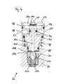
- FIG. 4 shows the control valve device 22 with sliding valve seat 108 in a parking position. If the control valve device 22 of the in FIG. 2 shown switching state, the driving state, in the in FIG. 4 shown switching state, the park state, transferred, the working port 20 is vented. As a result, the springs 98, 112 can move the control piston 100 against the decreasing pressure in the working space. In this case, the displaceable valve seat piston 110 follows the control piston 100. A thus assumed intermediate state is in FIG. 3 shown. The control piston 100 has already moved in a direction decreasing the working space 104, but the valve seat 108 still seals the working space 104 against the vent space 106.
- this spring 112 obstructs the initial movement of the control piston 100 in the transition from parked position FIG. 4 according to the driving position FIG. 2 Not.
- the vent port 70 in the state according to FIG. 4 is pressurized, also builds a pressure in the working space 104 and, in external wiring according to FIG. 1 , at the control input 50 of the control valve device 22.
- the force of the spring 98 and the static friction of the O-rings 88, 90, 92 must be overcome, but not the force of the spring 112.
- the initial movement of the spool 100 is assisted by ventilating the vent outlet 70.
- This is done by energizing the control and vent solenoid valve 72. If the valve seat piston 110 is then arranged in the valve housing 84 in such a way that its the valve seat 108 facing away, so the spring 112 facing surface 124 is acted upon by the supplied via the vent port 70, so The resulting force in a useful manner supports the movement of the control piston in the direction of the second valve seat 114.
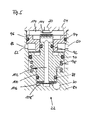
- FIG. 5 shows a control valve device 22 with a fixed valve seat 108 'in a driving position.
- the control valve device 22 according to FIG. 5 no sliding valve seat piston. Rather, the valve seat 108 'is fixed. Nevertheless, the transition from the in FIG. 5 illustrated driving position to the in FIG. 6 illustrated parking position can be supported by the vent port 70 is vented while the work port 20 is vented.
- control valve devices are guided and sealed by three O-rings 88, 90, 92.
- the active surfaces of the control piston 100 are designed so that a transition from the parking position to the driving position with energized control and ventilation solenoid valve device 72 according to FIG. 1 he follows. Once the control valve device 22 is then switched to the driving position, the control and vent valve device 72 can be transferred without effect for the switching state of the control valve device 22 in its de-energized state.
- FIG. 7 shows a control valve device 22 with a two radial seals 88, 92 having control piston 100 in a driving position.
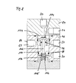
- FIG. 8 shows the control valve device 22 with a two radial seals 88, 92 having control piston 100 in a parking position.
- the control valve device 22 shown here has a control piston 100, which is guided over only two radial seals, namely the O-rings 88, 92.
- the ratios of the active surfaces are taking into account the force of the spring 116 such that the control valve device 22 is not energized by energized control and vent solenoid valve 72 from its in FIG. 8 Parking position shown in their in FIG. 7 shown driving position is transferred.
- the control valve device 22 according to the FIGS. 7 and 8th has a fixed valve seat 108 '. However, it can also be equipped with a sliding valve seat.
- FIGS. 9 to 11 show schematically an electric parking brake system in three different switching states. That in the FIGS. 9 to 11 shown system differs from that in FIG. 1 illustrated system essentially in that in the control line 48, the trailer control line branch 42, and the trailer control line branch 44 leading input port of the select-low valve 46 throttles 118, 120, 122 are provided.
- the control valve device 22 may have a throttle in the venting path of its control piston. Shall now a transition from the in FIG. 9 illustrated state, which corresponds to the parking position, in the in FIG. 11 illustrated state, which corresponds to the driving position, carried out, so first the control and bleed solenoid valve 72 is switched, as in FIG. 10 shown. As related to the FIGS.
- control valve means 22 may be designed so that the thereby adjusting pressure conditions do not lead to a switching of the control valve device 22. If, however, a certain pressure level in the control line 48 has built up after a certain energizing time of the control and venting solenoid valve device 72, then the control valve device 22 can be switched over by virtue of a currentless switching of the control and venting solenoid valve device 72 into its venting connection 70 of the control valve device 22 venting state is transferred. Due to the throttle 118 For example, the pressure at the venting port 70 may decrease faster than at the control input 48.
Landscapes
- Engineering & Computer Science (AREA)
- Transportation (AREA)
- Mechanical Engineering (AREA)
- Valves And Accessory Devices For Braking Systems (AREA)
- Braking Systems And Boosters (AREA)
Applications Claiming Priority (1)
| Application Number | Priority Date | Filing Date | Title |
|---|---|---|---|
| DE102009059899A DE102009059899A1 (de) | 2009-12-21 | 2009-12-21 | Verfahren zum Steuern eines elektrisch betätigbaren Feststellbremssystems |
Publications (3)
| Publication Number | Publication Date |
|---|---|
| EP2384944A2 true EP2384944A2 (fr) | 2011-11-09 |
| EP2384944A3 EP2384944A3 (fr) | 2012-12-19 |
| EP2384944B1 EP2384944B1 (fr) | 2014-03-12 |
Family
ID=44012392
Family Applications (1)
| Application Number | Title | Priority Date | Filing Date |
|---|---|---|---|
| EP20100195133 Active EP2384944B1 (fr) | 2009-12-21 | 2010-12-15 | Procédé de commande d'un système de frein de stationnement pouvant être actionné de manière électrique |
Country Status (2)
| Country | Link |
|---|---|
| EP (1) | EP2384944B1 (fr) |
| DE (1) | DE102009059899A1 (fr) |
Cited By (1)
| Publication number | Priority date | Publication date | Assignee | Title |
|---|---|---|---|---|
| US11400906B2 (en) | 2017-08-16 | 2022-08-02 | Wabco Gmbh | Electropneumatic parking brake with directly controlled valves |
Families Citing this family (1)
| Publication number | Priority date | Publication date | Assignee | Title |
|---|---|---|---|---|
| CN103863289B (zh) * | 2014-03-28 | 2017-09-19 | 徐州重型机械有限公司 | 一种气压式电控驻车制动系统 |
Citations (1)
| Publication number | Priority date | Publication date | Assignee | Title |
|---|---|---|---|---|
| DE102008007877B3 (de) | 2008-02-06 | 2009-11-26 | Knorr-Bremse Systeme für Nutzfahrzeuge GmbH | Parkbremseinrichtung |
Family Cites Families (1)
| Publication number | Priority date | Publication date | Assignee | Title |
|---|---|---|---|---|
| DE102007051151B4 (de) * | 2007-04-23 | 2010-04-08 | Knorr-Bremse Systeme für Nutzfahrzeuge GmbH | Nutzfahrzeugbremsanlage |
-
2009
- 2009-12-21 DE DE102009059899A patent/DE102009059899A1/de not_active Ceased
-
2010
- 2010-12-15 EP EP20100195133 patent/EP2384944B1/fr active Active
Patent Citations (1)
| Publication number | Priority date | Publication date | Assignee | Title |
|---|---|---|---|---|
| DE102008007877B3 (de) | 2008-02-06 | 2009-11-26 | Knorr-Bremse Systeme für Nutzfahrzeuge GmbH | Parkbremseinrichtung |
Cited By (1)
| Publication number | Priority date | Publication date | Assignee | Title |
|---|---|---|---|---|
| US11400906B2 (en) | 2017-08-16 | 2022-08-02 | Wabco Gmbh | Electropneumatic parking brake with directly controlled valves |
Also Published As
| Publication number | Publication date |
|---|---|
| EP2384944B1 (fr) | 2014-03-12 |
| DE102009059899A1 (de) | 2011-07-07 |
| EP2384944A3 (fr) | 2012-12-19 |
Similar Documents
| Publication | Publication Date | Title |
|---|---|---|
| EP2384943B1 (fr) | Dispositif de soupape, système de frein de stationnement pouvant être actionné de manière électrique et procédé de commande d'un système de frein de stationnement pouvant être actionné de manière électrique | |
| EP2338753B1 (fr) | Système de frein de stationnement pouvant être actionné de manière électrique et procédé de commande d'un système de frein de stationnement pouvant être actionné de manière électrique | |
| EP2547565B1 (fr) | Système de frein de stationnement à commande électrique | |
| EP3755589B1 (fr) | Équipement électropneumatique d'un véhicule | |
| DE102015114176C5 (de) | Elektrische Parkbremseinrichtung mit zusätzlicher Energieversorgung | |
| EP3694755B1 (fr) | Module electromagnetique de frein de stationnement pour camion avec freins a ressort | |
| EP2576301B1 (fr) | Système de freinage de stationnement électrique, et procédé pour faire fonctionner un système de freinage de stationnement électrique | |
| EP2099666B1 (fr) | Dispositif de frein de stationnement équipé d'un dispositif de desserrage d'urgence et procédé associé | |
| EP2298616B1 (fr) | Appareil de commande et procédé de test d'un dispositif de soupape d'un frein de stationnement électrique | |
| EP3870485B1 (fr) | Architecture de système de freinage électropneumatique sans redondance de freinage de fonctionnement pneumatique directe sur l'essieu arrière (1p1e) | |
| EP2407355B1 (fr) | Soupape de relais et procédé de fonctionnement d'une soupape de relais | |
| EP2731839A2 (fr) | Installation de préparation d'air comprimé et procédé servant à faire fonctionner une installation de préparation d'air comprimé | |
| EP2338754B1 (fr) | Système de frein de stationnement pouvant être actionné de manière électrique et procédé de commande d'un système de frein de stationnement pouvant être actionné de manière électrique | |
| EP3286052B1 (fr) | Arrangement de frein de parking pour véhicules | |
| EP2094547B1 (fr) | Dispositif de frein de stationnement équipé de conduits d'alimentation en air comprimé | |
| EP2384944B1 (fr) | Procédé de commande d'un système de frein de stationnement pouvant être actionné de manière électrique | |
| DE102015106144A1 (de) | Steuerventileinrichtung für eine Parkbremseinrichtung für Kraftfahrzeuge sowie Parkbremseinrichtung für Kraftfahrzeuge | |
| DE102009055210B4 (de) | Druckluftanlage |
Legal Events
| Date | Code | Title | Description |
|---|---|---|---|
| AK | Designated contracting states |
Kind code of ref document: A2 Designated state(s): AL AT BE BG CH CY CZ DE DK EE ES FI FR GB GR HR HU IE IS IT LI LT LU LV MC MK MT NL NO PL PT RO RS SE SI SK SM TR |
|
| AX | Request for extension of the european patent |
Extension state: BA ME |
|
| PUAI | Public reference made under article 153(3) epc to a published international application that has entered the european phase |
Free format text: ORIGINAL CODE: 0009012 |
|
| RIN1 | Information on inventor provided before grant (corrected) |
Inventor name: KAUPERT, OLIVER Inventor name: SCHNITTGER, KARSTEN Inventor name: USLU, MUSTAFA |
|
| PUAL | Search report despatched |
Free format text: ORIGINAL CODE: 0009013 |
|
| AK | Designated contracting states |
Kind code of ref document: A3 Designated state(s): AL AT BE BG CH CY CZ DE DK EE ES FI FR GB GR HR HU IE IS IT LI LT LU LV MC MK MT NL NO PL PT RO RS SE SI SK SM TR |
|
| AX | Request for extension of the european patent |
Extension state: BA ME |
|
| RIC1 | Information provided on ipc code assigned before grant |
Ipc: B60T 13/66 20060101ALI20121112BHEP Ipc: B60T 13/58 20060101ALI20121112BHEP Ipc: B60T 13/68 20060101AFI20121112BHEP |
|
| 17P | Request for examination filed |
Effective date: 20130619 |
|
| RBV | Designated contracting states (corrected) |
Designated state(s): AL AT BE BG CH CY CZ DE DK EE ES FI FR GB GR HR HU IE IS IT LI LT LU LV MC MK MT NL NO PL PT RO RS SE SI SK SM TR |
|
| RIC1 | Information provided on ipc code assigned before grant |
Ipc: B60T 13/68 20060101AFI20130708BHEP Ipc: B60T 13/58 20060101ALI20130708BHEP Ipc: B60T 13/66 20060101ALI20130708BHEP |
|
| GRAP | Despatch of communication of intention to grant a patent |
Free format text: ORIGINAL CODE: EPIDOSNIGR1 |
|
| INTG | Intention to grant announced |
Effective date: 20131125 |
|
| GRAS | Grant fee paid |
Free format text: ORIGINAL CODE: EPIDOSNIGR3 |
|
| GRAA | (expected) grant |
Free format text: ORIGINAL CODE: 0009210 |
|
| RIN1 | Information on inventor provided before grant (corrected) |
Inventor name: SCHNITTGER, KARSTEN Inventor name: USLU, MUSTAFA Inventor name: KAUPERT, OLIVER |
|
| AK | Designated contracting states |
Kind code of ref document: B1 Designated state(s): AL AT BE BG CH CY CZ DE DK EE ES FI FR GB GR HR HU IE IS IT LI LT LU LV MC MK MT NL NO PL PT RO RS SE SI SK SM TR |
|
| REG | Reference to a national code |
Ref country code: GB Ref legal event code: FG4D Free format text: NOT ENGLISH |
|
| REG | Reference to a national code |
Ref country code: CH Ref legal event code: EP |
|
| REG | Reference to a national code |
Ref country code: AT Ref legal event code: REF Ref document number: 656064 Country of ref document: AT Kind code of ref document: T Effective date: 20140315 |
|
| REG | Reference to a national code |
Ref country code: IE Ref legal event code: FG4D Free format text: LANGUAGE OF EP DOCUMENT: GERMAN |
|
| REG | Reference to a national code |
Ref country code: DE Ref legal event code: R096 Ref document number: 502010006342 Country of ref document: DE Effective date: 20140424 |
|
| REG | Reference to a national code |
Ref country code: SE Ref legal event code: TRGR |
|
| REG | Reference to a national code |
Ref country code: NL Ref legal event code: T3 |
|
| PG25 | Lapsed in a contracting state [announced via postgrant information from national office to epo] |
Ref country code: NO Free format text: LAPSE BECAUSE OF FAILURE TO SUBMIT A TRANSLATION OF THE DESCRIPTION OR TO PAY THE FEE WITHIN THE PRESCRIBED TIME-LIMIT Effective date: 20140612 Ref country code: LT Free format text: LAPSE BECAUSE OF FAILURE TO SUBMIT A TRANSLATION OF THE DESCRIPTION OR TO PAY THE FEE WITHIN THE PRESCRIBED TIME-LIMIT Effective date: 20140312 |
|
| REG | Reference to a national code |
Ref country code: LT Ref legal event code: MG4D |
|
| PG25 | Lapsed in a contracting state [announced via postgrant information from national office to epo] |
Ref country code: CY Free format text: LAPSE BECAUSE OF FAILURE TO SUBMIT A TRANSLATION OF THE DESCRIPTION OR TO PAY THE FEE WITHIN THE PRESCRIBED TIME-LIMIT Effective date: 20140312 Ref country code: FI Free format text: LAPSE BECAUSE OF FAILURE TO SUBMIT A TRANSLATION OF THE DESCRIPTION OR TO PAY THE FEE WITHIN THE PRESCRIBED TIME-LIMIT Effective date: 20140312 |
|
| PG25 | Lapsed in a contracting state [announced via postgrant information from national office to epo] |
Ref country code: HR Free format text: LAPSE BECAUSE OF FAILURE TO SUBMIT A TRANSLATION OF THE DESCRIPTION OR TO PAY THE FEE WITHIN THE PRESCRIBED TIME-LIMIT Effective date: 20140312 Ref country code: RS Free format text: LAPSE BECAUSE OF FAILURE TO SUBMIT A TRANSLATION OF THE DESCRIPTION OR TO PAY THE FEE WITHIN THE PRESCRIBED TIME-LIMIT Effective date: 20140312 Ref country code: LV Free format text: LAPSE BECAUSE OF FAILURE TO SUBMIT A TRANSLATION OF THE DESCRIPTION OR TO PAY THE FEE WITHIN THE PRESCRIBED TIME-LIMIT Effective date: 20140312 |
|
| PG25 | Lapsed in a contracting state [announced via postgrant information from national office to epo] |
Ref country code: RO Free format text: LAPSE BECAUSE OF FAILURE TO SUBMIT A TRANSLATION OF THE DESCRIPTION OR TO PAY THE FEE WITHIN THE PRESCRIBED TIME-LIMIT Effective date: 20140312 Ref country code: BG Free format text: LAPSE BECAUSE OF FAILURE TO SUBMIT A TRANSLATION OF THE DESCRIPTION OR TO PAY THE FEE WITHIN THE PRESCRIBED TIME-LIMIT Effective date: 20140612 Ref country code: CZ Free format text: LAPSE BECAUSE OF FAILURE TO SUBMIT A TRANSLATION OF THE DESCRIPTION OR TO PAY THE FEE WITHIN THE PRESCRIBED TIME-LIMIT Effective date: 20140312 Ref country code: EE Free format text: LAPSE BECAUSE OF FAILURE TO SUBMIT A TRANSLATION OF THE DESCRIPTION OR TO PAY THE FEE WITHIN THE PRESCRIBED TIME-LIMIT Effective date: 20140312 Ref country code: IS Free format text: LAPSE BECAUSE OF FAILURE TO SUBMIT A TRANSLATION OF THE DESCRIPTION OR TO PAY THE FEE WITHIN THE PRESCRIBED TIME-LIMIT Effective date: 20140712 |
|
| PG25 | Lapsed in a contracting state [announced via postgrant information from national office to epo] |
Ref country code: ES Free format text: LAPSE BECAUSE OF FAILURE TO SUBMIT A TRANSLATION OF THE DESCRIPTION OR TO PAY THE FEE WITHIN THE PRESCRIBED TIME-LIMIT Effective date: 20140312 Ref country code: SK Free format text: LAPSE BECAUSE OF FAILURE TO SUBMIT A TRANSLATION OF THE DESCRIPTION OR TO PAY THE FEE WITHIN THE PRESCRIBED TIME-LIMIT Effective date: 20140312 Ref country code: PL Free format text: LAPSE BECAUSE OF FAILURE TO SUBMIT A TRANSLATION OF THE DESCRIPTION OR TO PAY THE FEE WITHIN THE PRESCRIBED TIME-LIMIT Effective date: 20140312 |
|
| REG | Reference to a national code |
Ref country code: DE Ref legal event code: R097 Ref document number: 502010006342 Country of ref document: DE |
|
| PG25 | Lapsed in a contracting state [announced via postgrant information from national office to epo] |
Ref country code: PT Free format text: LAPSE BECAUSE OF FAILURE TO SUBMIT A TRANSLATION OF THE DESCRIPTION OR TO PAY THE FEE WITHIN THE PRESCRIBED TIME-LIMIT Effective date: 20140714 |
|
| PLBE | No opposition filed within time limit |
Free format text: ORIGINAL CODE: 0009261 |
|
| STAA | Information on the status of an ep patent application or granted ep patent |
Free format text: STATUS: NO OPPOSITION FILED WITHIN TIME LIMIT |
|
| PG25 | Lapsed in a contracting state [announced via postgrant information from national office to epo] |
Ref country code: DK Free format text: LAPSE BECAUSE OF FAILURE TO SUBMIT A TRANSLATION OF THE DESCRIPTION OR TO PAY THE FEE WITHIN THE PRESCRIBED TIME-LIMIT Effective date: 20140312 |
|
| 26N | No opposition filed |
Effective date: 20141215 |
|
| PG25 | Lapsed in a contracting state [announced via postgrant information from national office to epo] |
Ref country code: RS Free format text: LAPSE BECAUSE OF FAILURE TO SUBMIT A TRANSLATION OF THE DESCRIPTION OR TO PAY THE FEE WITHIN THE PRESCRIBED TIME-LIMIT Effective date: 20140903 |
|
| REG | Reference to a national code |
Ref country code: DE Ref legal event code: R097 Ref document number: 502010006342 Country of ref document: DE Effective date: 20141215 |
|
| PG25 | Lapsed in a contracting state [announced via postgrant information from national office to epo] |
Ref country code: BE Free format text: LAPSE BECAUSE OF NON-PAYMENT OF DUE FEES Effective date: 20141231 |
|
| PG25 | Lapsed in a contracting state [announced via postgrant information from national office to epo] |
Ref country code: LU Free format text: LAPSE BECAUSE OF FAILURE TO SUBMIT A TRANSLATION OF THE DESCRIPTION OR TO PAY THE FEE WITHIN THE PRESCRIBED TIME-LIMIT Effective date: 20141215 Ref country code: SI Free format text: LAPSE BECAUSE OF FAILURE TO SUBMIT A TRANSLATION OF THE DESCRIPTION OR TO PAY THE FEE WITHIN THE PRESCRIBED TIME-LIMIT Effective date: 20140312 |
|
| REG | Reference to a national code |
Ref country code: CH Ref legal event code: PL |
|
| REG | Reference to a national code |
Ref country code: IE Ref legal event code: MM4A |
|
| PG25 | Lapsed in a contracting state [announced via postgrant information from national office to epo] |
Ref country code: LI Free format text: LAPSE BECAUSE OF NON-PAYMENT OF DUE FEES Effective date: 20141231 Ref country code: CH Free format text: LAPSE BECAUSE OF NON-PAYMENT OF DUE FEES Effective date: 20141231 Ref country code: IE Free format text: LAPSE BECAUSE OF NON-PAYMENT OF DUE FEES Effective date: 20141215 |
|
| REG | Reference to a national code |
Ref country code: FR Ref legal event code: PLFP Year of fee payment: 6 |
|
| PG25 | Lapsed in a contracting state [announced via postgrant information from national office to epo] |
Ref country code: SM Free format text: LAPSE BECAUSE OF FAILURE TO SUBMIT A TRANSLATION OF THE DESCRIPTION OR TO PAY THE FEE WITHIN THE PRESCRIBED TIME-LIMIT Effective date: 20140312 |
|
| PG25 | Lapsed in a contracting state [announced via postgrant information from national office to epo] |
Ref country code: MC Free format text: LAPSE BECAUSE OF FAILURE TO SUBMIT A TRANSLATION OF THE DESCRIPTION OR TO PAY THE FEE WITHIN THE PRESCRIBED TIME-LIMIT Effective date: 20140312 |
|
| PG25 | Lapsed in a contracting state [announced via postgrant information from national office to epo] |
Ref country code: GR Free format text: LAPSE BECAUSE OF FAILURE TO SUBMIT A TRANSLATION OF THE DESCRIPTION OR TO PAY THE FEE WITHIN THE PRESCRIBED TIME-LIMIT Effective date: 20140613 |
|
| PG25 | Lapsed in a contracting state [announced via postgrant information from national office to epo] |
Ref country code: HU Free format text: LAPSE BECAUSE OF FAILURE TO SUBMIT A TRANSLATION OF THE DESCRIPTION OR TO PAY THE FEE WITHIN THE PRESCRIBED TIME-LIMIT; INVALID AB INITIO Effective date: 20101215 Ref country code: MT Free format text: LAPSE BECAUSE OF FAILURE TO SUBMIT A TRANSLATION OF THE DESCRIPTION OR TO PAY THE FEE WITHIN THE PRESCRIBED TIME-LIMIT Effective date: 20140312 |
|
| REG | Reference to a national code |
Ref country code: FR Ref legal event code: PLFP Year of fee payment: 7 |
|
| REG | Reference to a national code |
Ref country code: AT Ref legal event code: MM01 Ref document number: 656064 Country of ref document: AT Kind code of ref document: T Effective date: 20151215 |
|
| PG25 | Lapsed in a contracting state [announced via postgrant information from national office to epo] |
Ref country code: AT Free format text: LAPSE BECAUSE OF NON-PAYMENT OF DUE FEES Effective date: 20151215 |
|
| REG | Reference to a national code |
Ref country code: FR Ref legal event code: PLFP Year of fee payment: 8 |
|
| PGFP | Annual fee paid to national office [announced via postgrant information from national office to epo] |
Ref country code: TR Payment date: 20171213 Year of fee payment: 8 |
|
| PG25 | Lapsed in a contracting state [announced via postgrant information from national office to epo] |
Ref country code: MK Free format text: LAPSE BECAUSE OF FAILURE TO SUBMIT A TRANSLATION OF THE DESCRIPTION OR TO PAY THE FEE WITHIN THE PRESCRIBED TIME-LIMIT Effective date: 20140312 |
|
| PG25 | Lapsed in a contracting state [announced via postgrant information from national office to epo] |
Ref country code: AL Free format text: LAPSE BECAUSE OF FAILURE TO SUBMIT A TRANSLATION OF THE DESCRIPTION OR TO PAY THE FEE WITHIN THE PRESCRIBED TIME-LIMIT Effective date: 20140312 |
|
| PGFP | Annual fee paid to national office [announced via postgrant information from national office to epo] |
Ref country code: NL Payment date: 20181219 Year of fee payment: 9 |
|
| REG | Reference to a national code |
Ref country code: NL Ref legal event code: MM Effective date: 20200101 |
|
| PG25 | Lapsed in a contracting state [announced via postgrant information from national office to epo] |
Ref country code: NL Free format text: LAPSE BECAUSE OF NON-PAYMENT OF DUE FEES Effective date: 20200101 |
|
| PG25 | Lapsed in a contracting state [announced via postgrant information from national office to epo] |
Ref country code: IT Free format text: LAPSE BECAUSE OF NON-PAYMENT OF DUE FEES Effective date: 20191215 |
|
| PG25 | Lapsed in a contracting state [announced via postgrant information from national office to epo] |
Ref country code: TR Free format text: LAPSE BECAUSE OF NON-PAYMENT OF DUE FEES Effective date: 20201215 |
|
| P01 | Opt-out of the competence of the unified patent court (upc) registered |
Effective date: 20230607 |
|
| PGFP | Annual fee paid to national office [announced via postgrant information from national office to epo] |
Ref country code: GB Payment date: 20251223 Year of fee payment: 16 |
|
| PGFP | Annual fee paid to national office [announced via postgrant information from national office to epo] |
Ref country code: FR Payment date: 20251230 Year of fee payment: 16 |
|
| PGFP | Annual fee paid to national office [announced via postgrant information from national office to epo] |
Ref country code: SE Payment date: 20251222 Year of fee payment: 16 |
|
| PGFP | Annual fee paid to national office [announced via postgrant information from national office to epo] |
Ref country code: DE Payment date: 20251229 Year of fee payment: 16 |