EP2384966A2 - Blattwinkelverstellmechanismus - Google Patents
Blattwinkelverstellmechanismus Download PDFInfo
- Publication number
- EP2384966A2 EP2384966A2 EP11162479A EP11162479A EP2384966A2 EP 2384966 A2 EP2384966 A2 EP 2384966A2 EP 11162479 A EP11162479 A EP 11162479A EP 11162479 A EP11162479 A EP 11162479A EP 2384966 A2 EP2384966 A2 EP 2384966A2
- Authority
- EP
- European Patent Office
- Prior art keywords
- gear
- epicyclic
- assembly
- drive
- propeller assembly
- Prior art date
- Legal status (The legal status is an assumption and is not a legal conclusion. Google has not performed a legal analysis and makes no representation as to the accuracy of the status listed.)
- Granted
Links
Images

Classifications
-
- B—PERFORMING OPERATIONS; TRANSPORTING
- B64—AIRCRAFT; AVIATION; COSMONAUTICS
- B64C—AEROPLANES; HELICOPTERS
- B64C11/00—Propellers, e.g. of ducted type; Features common to propellers and rotors for rotorcraft
- B64C11/30—Blade pitch-changing mechanisms
- B64C11/32—Blade pitch-changing mechanisms mechanical
-
- B—PERFORMING OPERATIONS; TRANSPORTING
- B64—AIRCRAFT; AVIATION; COSMONAUTICS
- B64D—EQUIPMENT FOR FITTING IN OR TO AIRCRAFT; FLIGHT SUITS; PARACHUTES; ARRANGEMENT OR MOUNTING OF POWER PLANTS OR PROPULSION TRANSMISSIONS IN AIRCRAFT
- B64D27/00—Arrangement or mounting of power plants in aircraft; Aircraft characterised by the type or position of power plants
- B64D27/02—Aircraft characterised by the type or position of power plants
- B64D27/30—Aircraft characterised by electric power plants
- B64D27/33—Hybrid electric aircraft
-
- B—PERFORMING OPERATIONS; TRANSPORTING
- B64—AIRCRAFT; AVIATION; COSMONAUTICS
- B64D—EQUIPMENT FOR FITTING IN OR TO AIRCRAFT; FLIGHT SUITS; PARACHUTES; ARRANGEMENT OR MOUNTING OF POWER PLANTS OR PROPULSION TRANSMISSIONS IN AIRCRAFT
- B64D27/00—Arrangement or mounting of power plants in aircraft; Aircraft characterised by the type or position of power plants
- B64D27/02—Aircraft characterised by the type or position of power plants
- B64D27/026—Aircraft characterised by the type or position of power plants comprising different types of power plants, e.g. combination of a piston engine and a gas-turbine
Definitions
- the present invention relates to a pitch control mechanism, and more particularly to a pitch control mechanism for angular displacement of propellers of a propeller assembly.
- Aero propellers either single rotor or contra-rotating, usually have a means of varying the blade pitch via a pitch control mechanism (PCM), to optimise efficiency of thrust delivery and to reduce noise throughout the flight envelope, to provide reverse thrust, and to be able to feather the blades to control drag and rotor speed in some powerplant failure cases.
- PCM pitch control mechanism
- the power source can be in the static or rotating field, although it is more common for it to be in the static field to avoid static to rotating control communication issues and for easier line replacement of faulty components. However, where the power source is in the static field, a means of transferring the power to the rotating field(s) is required.
- slip rings For a static electrical power source the transfer is typically achieved via slip rings. These are used on single propeller assembly turboprop engines. However, they suffer from a high maintenance burden. Further, on an engine having two contra-rotating propeller assemblies, and particularly such an engine where the exhaust is ducted under the propeller blade roots, the slip rings would experience very high operating speeds which would significantly reduce slip ring life. The high speeds result from a need to locate the rings at large radial distances in a non-oily zone, as well as from the high relative speeds caused by contra-rotation. Thus slip rings are not seen as a viable solution for power source transfer in contra-rotating propeller assemblies.
- the transfer can be achieved by rotating hydraulic couplings.
- the propeller assembly may be driven by a hollow propeller shaft.
- a rotating hydraulic coupling can be provided at one end of the propeller shaft, with hydraulic supply lines running inside the shaft from the coupling to a PCM prime mover (e.g. a hydraulic actuator) adjacent the propeller blades.
- the propeller shaft, supply lines and prime mover are all in the rotating field.
- a hydraulic pressure power source which is in the static field, supplies hydraulic fluid to the coupling, and thence to the supply lines.
- Turboprop engines whether having a single propeller assembly or two contra-rotating propeller assemblies, employ a reduction gearbox.
- a gearbox 1 can be of a step-aside shaft configuration in which a drive shaft 2 extending from the free power turbine 3 of the engine 4 is laterally offset from the propeller shaft 5 of the propeller assembly 6.
- a small diameter, and hence low PV value and low leakage hydraulic coupling 7 may be located at the rear of the gearbox on the end of the propeller shaft, which is hollow.
- supply lines 8 can run along the inside of the propeller shaft to supply a hydraulic actuator 9, which rotates with the propeller assembly, with hydraulic fluid from a static hydraulic pressure power source 10.
- the gearbox 1 can be of a coaxial epicyclic configuration, in which typically a sun gear of the gearbox is driven by and coaxial with the drive shaft 2 extending from the free power turbine 3 of the engine 4.
- the gearbox 1 can be of a coaxial epicyclic configuration, in which typically a sun gear of the gearbox is driven by and coaxial with the drive shaft 2 extending from the free power turbine 3 of the engine 4.
- the axis of the propeller, gearbox and gas generator are coincident, it is more problematic to arrange for a small diameter hydraulic coupling 7 with an acceptably low PV value and low leakage rate because the static part of the coupling is outside the propeller shaft 5 outer diameter.
- EP A 1881176 proposes an arrangement for transferring hydraulic power from a static hydraulic power source to the respective hydraulic actuators of a contra-rotating turboprop engine which avoids the need for rotating hydraulic couplings, even though the engine has in-line coaxial epicylic gear assembly.
- the hydraulic actuators are statically mounted, and the power transfer between the static and rotating fields is achieved by rolling element thrust bearings and associated transfer rods. More particularly, to transfer power to the propeller blade angle adjustment mechanism of the second propeller assembly which is on the other side of the gear assembly from its hydraulic actuator, a first set of transfer rods extend from rolling element thrust bearings at the statically mounted hydraulic actuator through the carrier of the gear assembly planetary gears. As the carrier rotates with the first propeller assembly, a second set of transfer rods then extend from further rolling element thrust bearings between the two sets of rods to the contra-rotating, blade angle adjustment mechanism of the second propeller assembly.
- a first aspect of the present invention provides a pitch control mechanism for angular displacement of propellers of a propeller assembly of an engine arrangement, the pitch control mechanism having:
- the pitch control mechanism enables the transfer of mechanical pitch control signals (via the varying a rotation of at least one of the drive gear and the control gear) across the rotating interface between the static structure and the propeller assembly.
- the engine arrangement may have any one or, to the extent they are compatible, any combination of the following optional features.
- the ring gear can be the first epicyclic input
- the planet carrier can be the second epicyclic input
- the sun gear can be the epicyclic output.
- this arrangement can be implemented with little or no additional gearing between the sun gear and the drive mechanism.
- the planet carrier could be the epicyclic output with the sun gear being the input, but in this case additional gearing may be needed to transmit rotary motion from the control gear to the sun gear.
- one of the drive gear and control gear can be static and the other of the drive gear and control gear can be variably rotatable.
- the control gear is static and the drive gear is variably rotatable.
- the gear ratio of the drive gear to the first epicyclic input and the gear ratio of the control gear to the second epicyclic input can be selected such that, when both the drive gear and the control gear are static, the epicyclic output is static in the rotating frame of reference of the propeller assembly. In this way, when both the drive gear and the control gear static, there can be no angular displacement of the propellers.
- the drive mechanism comprises a screw and an actuation member which is threadingly but non-rotatably engaged to one end of the screw.
- the screw and the actuation member can form a ball or roller screw arrangement, the threading engagement of the actuation member to the screw being mediated by ball or roller bearings.
- the other end of the screw can then accept rotary motion from the epicyclic output, and the rotary motion can be converted into translational output motion of the actuation member.
- other arrangements can be adopted for transferring rotary motion from the epicyclic output to an actuation member.
- the actuation member is, or is operatively connected to, a unison ring which is coaxial with the propeller assembly.
- the unison ring can then operate drive systems for angular displacement of respective propellers.
- each drive system operated on by the unison ring can conveniently comprise a lever arm or cam follower at the end of a quill shaft extending from the base of the respective propeller.
- Translating the unison ring in the axial direction of the propeller assembly thus turns the lever arm or cam follower to vary the pitch of the propeller.
- the unison ring can be installed coaxially to the propeller assembly, but not in the central zone along its rotational axis, which zone is not always available in engines having in-line propeller arrangements.
- the pitch control mechanism can be used to control the pitch of the forward propeller assembly of a propeller engine with a pair of contra-rotating "pusher” propeller blade assemblies driven by an in-line gear assembly, or the rear propeller assembly of a propeller engine with a pair of contra-rotating "puller” propeller blade assemblies driven by an in-line gear assembly.
- the pitch control mechanism further has an electric motor for powering the variable rotation of at least one of the drive gear and the control gear.
- the electric motor powers the variable rotation of the drive gear, the control gear usually being static.
- a second aspect of the invention provides an engine arrangement having:
- the engine arrangement may have any one or, to the extent they are compatible, any combination of the following optional features.
- the engine arrangement may further have:
- the motor can be mounted to the projecting portion of the static conduit, and the first power line can be an electrical power line extending to the motor.
- the motor is thus adjacent the drive and control gears, and the static conduit provides a convenient means for extending the power line to the motor.
- the arrangement can be used for engines having a single propeller assembly.
- the engine arrangement is for a contra-rotating engine, the arrangement further having:
- the second pitch control mechanism further has a second electric motor for powering the variable rotation of the second pitch control mechanism.
- the second motor can also be mounted to the projecting portion of the static conduit, and the second power line can be an electrical power line extending to the second motor.
- the engine arrangement may further have a power source, such as an electrical generator, from which the power line(s) extend.
- a power source such as an electrical generator
- the power source can be attached to an engine accessory gearbox.
- the gear assembly is an epicyclic gear assembly having e.g. a sun gear, and planetary gears driven by the sun gear and in turn driving a carrier.
- the power drive shaft can drive the sun gear
- the carrier can drive the first propeller assembly.
- the epicyclic gear assembly may further have a ring gear driven by the planetary gears.
- the ring gear can drive the second propeller assembly.
- the static conduit may penetrate an epicyclic gear assembly through the sun gear, which can help to avoid or reduce detrimental effects on gear assembly stiffness. Further, even if the gear assembly malfunctions, the ability of the power line or lines to power the variable rotation, and hence the ability to control the pitch of the propellers, is unlikely to be compromised.
- the first propeller assembly may be located at the first side of the gear assembly, and the epicyclic gear system of the first pitch change mechanism may be located at the second side of the gear assembly, the drive mechanism of the first pitch change mechanism penetrating through the gear assembly.
- Such an arrangement may be adopted, for example, in relation to a contra-rotating engine.
- the gear assembly is an epicyclic gear assembly and the first propeller assembly is driven by a carrier of the gear assembly, the drive mechanism of the first pitch change mechanism may penetrate through the carrier of the gear assembly.
- the second propeller assembly and the epicyclic gear system of the second pitch change mechanism are preferably located at the second side of the gear assembly.
- the drive mechanism of the second pitch change mechanism can then extend relatively unimpeded from its epicyclic gear system to the second propeller assembly.
- a third aspect of the present invention provides a gas turbine engine having an engine arrangement according to the second aspect with a gear assembly and static conduit arrangement, the engine comprising in flow series: (i) a generator section which includes one or more turbine subsections, one or more respective generator drive shafts extending axially forwardly from the turbine subsections to one or more corresponding generator compressor subsections, and (ii) a power turbine section, the power drive shaft extending axially rearwardly from the power turbine section, wherein a forward mouth of the static conduit opens to a gap formed between the forwardly extending generator drive shafts and the rearwardly extending power drive shaft, the, or each, power line entering the static conduit at said mouth.
- the gap thus provides a convenient means for routing the power supply line(s) into the static conduit.
- the engine may have any one or, to the extent they are compatible, any combination of the following optional features.
- the gas turbine engine is axially aligned with the gear assembly, which is preferably an epicyclic gear assembly.
- the gas turbine engine may have a row of nozzle guide vanes located at said gap, the, or each, power line being routed through a nozzle guide vane to arrive at said mouth.
- the nozzle guide vanes can thus protect the power line(s) from high working gas temperatures at the exit of the generator section of the engine.
- FIG. 3 An engine according to an embodiment of the present invention is shown in Figure 3 .
- the engine has a generator section 11 comprising in flow series low pressure 12a and high pressure 12b compressor subsections, a combustor subsection 13, and high pressure 14b and low pressure 14a turbine subsections.
- Generator drive shafts 15a, 15b connect the respective compressor and turbine subsections. Downstream of the generator section is a free power turbine 16 which drives a rearwardly extending power drive shaft 17.
- the distal end of the power drive shaft 17 drives a sun gear 18 of an epicyclic gear assembly which is coaxial with the power drive shaft.
- the sun gear drives planetary gears 19, which in turn drive a carrier (not shown) and a ring gear 20.
- the carrier and ring gear rotate in opposite directions.
- the carrier drives a first propeller assembly 21 a on the upstream side of the gear assembly, while the ring gear drives a contra-rotating second propeller assembly 21 b on the downstream side of the gear assembly.
- Each propeller assembly has a row of propeller blades 22a, 22b, with each blade being rotatable about its longitudinal axis to vary the blade pitch.
- the pitch variation for each propeller assembly is achieved by a respective pitch control mechanism (described below in more detail with reference to Figure 4 ) having an electric motor 33a, 33b, drive 31 and control 32 gears, an epicyclic gear system (30a, 30b, and a drive mechanism based on a ball screw 23a, 23b for delivering an output motion which moves a corresponding unison ring 24a, 24b in the axial direction of the engine.
- the axial movement of the unison rings rotates the blades via a quill shaft and lever or cam follower arrangement 25a, 25b which extends from the base of each blade.
- the power drive shaft 17 is hollow and a static conduit 26 extends along the internal cavity formed by the shaft.
- One end of the static conduit opens to a mouth 26a at the gap formed between the forward end of the power drive shaft and the rearward end of the low pressure generator drive shaft 15a.
- the other end of the static conduit penetrates through the centre of the sun gear 18 to form a projection 26b on the downstream side of the gear assembly.
- a power source 27, such as a generator, for providing electrical power for the pitch control mechanisms is attached to an accessory gearbox (not shown) of the engine remote from the actuators pitch control mechanisms.
- respective power lines 28a, 28b are routed from the source to the mouth 26a of the static conduit 26.
- the power lines traverse the working gas annulus of the engine through a row of nozzle guide vanes 29 which are located between the generator section 11 and the free power turbine 16. This arrangement protects the power lines from the high temperatures of the working gas.
- the supply lines are routed along the static conduit's internal cavity to arrive at the projection 26b on the downstream side of the gear assembly.
- the electric motors (33a, 33b) are mounted to the projection, the upstream one being a part of the pitch control mechanism of the first propeller assembly 21 a and the downstream one being a part of the pitch control mechanism of the second propeller assembly 21 b.
- the static conduit 26 can also be used to route other power control or lubrication lines through the engine, these lines being e.g. hydraulic or electrical.
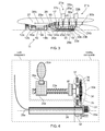
- Figure 4 shows schematically detail of the pitch control mechanism for angularly displacing the propeller blades 22a of the first propeller assembly 21 a of the engine of Figure 3 .
- extension of the static conduit 26 in the rearward direction beyond the motor 33a of the first pitch control mechanism is not shown.
- the dashed outlines divide components between those that are statically mounted and those that rotate with the first propeller assembly.
- the pitch control mechanism has an epicyclic gear system 30a comprising a sun gear 34, planet gears 35 which surround and mesh with the sun gear, and a ring gear 36 which surrounds and meshes with the planet gears.
- a planet carrier 37 carries the planet gears. The planet carrier and the ring gear are inputs to the epicyclic gear system and the sun gear is an output to epicyclic gear system.
- a shaft 38 extends forward from the axis of the sun gear, passing through the planet carrier to drive intermediate gearing 39.
- One end of a ball screw 23a accepts rotary motion from the intermediate gearing. The other end of the ball screw is threadingly engaged to the unison ring 24a of the first propeller assembly.
- the unison ring is prevented from rotating relative to the first propeller assembly and the ball screw.
- the rotary motion of the ball screw is converted into forward or aft axial movement of the unison ring, depending on the direction of rotation of the ball screw.
- the axial movement of the unison ring rotates the blades 22a of the first propeller assembly via a quill shaft and lever or cam follower arrangement 25a which extends from the base of each blade.
- the pitch control mechanism has a drive gear 31 and a control gear 32, both mounted to the projection 26b at the rearward end of the static conduit 26.
- the drive gear meshes with the ring gear, and the control gear meshing with the planet carrier.
- the drive and control gears both encircle the static conduit so that the ring gear and planet gear remain meshed as the first propeller assembly rotates.
- the control gear 32 is static, i.e. it does not rotate about the axis of the static conduit 26.
- the drive gear 31, on the other hand, is powered by the electric motor 33a and can be rotated about the axis of the static conduit.
- the ratio of the control gear and the planet carrier 37 and the ratio of the drive gear and the ring gear 36 are selected, however, so that, when the drive gear is not rotated, the planet carrier and ring gear inputs to the epicyclic gear system 30a cancel out, whereby the sun gear 34 remains static in the rotating frame of reference of the first propeller assembly 21 a.
- the drive gear is static, the blades 22a are not rotated.
- the sun gear 34 and blades 22a rotate in a corresponding direction
- the sun gear 34 and blades 22a also rotate in the opposite direction.
- the speed and duration of rotation of the drive gear determines the extent of rotation of the blades.
- the ball screw 23b of the pitch change mechanism for the second propeller assembly 21 b can extend unimpeded from the epicyclic gear system 30b to the unison ring 24b of the second propeller assembly.
- the ball screw 23a of the pitch change mechanism for the first propeller assembly 21 a has to pass through the epicyclic gear assembly at the distal end of the power drive shaft 17.
- the ball screw 23a can be routed between the planetary gears 19 and through the carrier of the epicyclic gear assembly, as the carrier rotates with the first propeller assembly.
- the pitch control mechanism provides a relatively simple method of transferring mechanical pitch control signals through a rotating interface, thereby allowing control without rotating hydraulic couplings, slip rings, wireless or electromagnetic rotating transfer devices.
- All the components of the pitch control mechanism can be located in positions which allow ready access for maintenance, cooling etc.
- Gearing in the pitch control mechanism does not need to be compounded. Therefore gearing efficiency can be improved, and power and heat losses, weight, and gear wear can be reduced.
Landscapes
- Engineering & Computer Science (AREA)
- Aviation & Aerospace Engineering (AREA)
- Mechanical Engineering (AREA)
- Retarders (AREA)
Applications Claiming Priority (1)
| Application Number | Priority Date | Filing Date | Title |
|---|---|---|---|
| GBGB1007569.5A GB201007569D0 (en) | 2010-05-06 | 2010-05-06 | Pitch control mechanism |
Publications (3)
| Publication Number | Publication Date |
|---|---|
| EP2384966A2 true EP2384966A2 (de) | 2011-11-09 |
| EP2384966A3 EP2384966A3 (de) | 2017-01-11 |
| EP2384966B1 EP2384966B1 (de) | 2018-10-17 |
Family
ID=42314913
Family Applications (1)
| Application Number | Title | Priority Date | Filing Date |
|---|---|---|---|
| EP11162479.7A Active EP2384966B1 (de) | 2010-05-06 | 2011-04-14 | Blattwinkelverstellmechanismus |
Country Status (3)
| Country | Link |
|---|---|
| US (1) | US8757976B2 (de) |
| EP (1) | EP2384966B1 (de) |
| GB (1) | GB201007569D0 (de) |
Cited By (4)
| Publication number | Priority date | Publication date | Assignee | Title |
|---|---|---|---|---|
| FR3032423A1 (fr) * | 2015-02-06 | 2016-08-12 | Snecma | Dispositif de calage de pas de pale |
| FR3049572A1 (fr) * | 2016-03-31 | 2017-10-06 | Snecma | Systeme de commande de pas d'helice |
| RU2633824C1 (ru) * | 2016-09-09 | 2017-10-18 | Сергей Александрович Савухин | Винтомоторная установка для малоразмерного летательного аппарата |
| CN109421924A (zh) * | 2017-08-28 | 2019-03-05 | 本田技研工业株式会社 | 多旋翼直升机 |
Families Citing this family (6)
| Publication number | Priority date | Publication date | Assignee | Title |
|---|---|---|---|---|
| FR3050432B1 (fr) * | 2016-04-20 | 2018-04-13 | Safran Aircraft Engines | Systeme d'actionnement de pas pour une helice de turbomachine |
| FR3050433B1 (fr) * | 2016-04-20 | 2020-08-28 | Snecma | Systeme simplifie d'actionnement de pas pour une helice de turbomachine |
| FR3060526B1 (fr) * | 2016-12-21 | 2019-05-10 | Safran Aircraft Engines | Systeme d'actionnement electromecanique de pas pour une helice de turbomachine |
| FR3066559B1 (fr) * | 2017-05-18 | 2019-06-07 | Safran Aircraft Engines | Module de soufflante a pales a calage variable |
| US12091157B2 (en) | 2022-09-07 | 2024-09-17 | Lockheed Martin Corporation | Actuator for pitch control for a rotor system of an aircraft |
| DE102022128671A1 (de) * | 2022-10-28 | 2024-05-08 | Rolls-Royce Deutschland Ltd & Co Kg | Zahnradpumpe, Antriebsvorrichtung und Verstellpropeller |
Citations (1)
| Publication number | Priority date | Publication date | Assignee | Title |
|---|---|---|---|---|
| EP1881176A2 (de) | 2006-07-19 | 2008-01-23 | Rolls-Royce plc | Motorenanordnung |
Family Cites Families (28)
| Publication number | Priority date | Publication date | Assignee | Title |
|---|---|---|---|---|
| GB531756A (en) * | 1939-06-14 | 1941-01-10 | John Stafford Northcote | Device employing epicyclic or bevel gears or a combination of both for controlling the pitch of variable pitch airscrews |
| DE880697C (de) * | 1944-12-31 | 1953-06-25 | Daimler Benz Ag | Stellgetriebe fuer die verstellbaren Blaetter von Luftschrauben |
| US2924281A (en) | 1953-06-11 | 1960-02-09 | Curtiss Wright Corp | Mechanical automatic propeller feathering |
| US2850106A (en) | 1955-10-05 | 1958-09-02 | Swan Aldon Edward | Reversible and variable pitch propeller |
| US3004608A (en) | 1957-09-16 | 1961-10-17 | United Aircraft Corp | Independent feathering system |
| US2980188A (en) | 1958-11-14 | 1961-04-18 | United Aircraft Corp | Combined feathering and pitch lock system |
| GB1041353A (en) | 1962-01-19 | 1966-09-07 | Konstantin Ivanovich Zhdanov | Aircraft propellor |
| GB1384383A (en) | 1971-08-26 | 1975-02-19 | Lips Nv | Variable pitch propeller with emergency control |
| GB1375988A (en) | 1971-12-11 | 1974-12-04 | Rolls Royce | Pitch varying mechanism for variable pitch fan |
| US4047842A (en) * | 1976-04-19 | 1977-09-13 | Curtiss-Wright Corporation | Variable pitch mechanism for fan blades |
| US4348155A (en) | 1980-03-17 | 1982-09-07 | United Technologies Corporation | Wind turbine blade pitch control system |
| US4878809A (en) | 1988-07-05 | 1989-11-07 | Sundstrand Corporation | Power source and control mechanism for propeller pitch control |
| GB8916714D0 (en) | 1989-07-21 | 1989-09-06 | Dowty Rotol Ltd | A propeller blade pitch control mechanism |
| US5042966A (en) | 1989-12-26 | 1991-08-27 | United Technologies Corporation | Pitch control system |
| US5037271A (en) | 1989-12-26 | 1991-08-06 | United Technologies Corporation | Pitch control system |
| US5242265A (en) | 1990-07-23 | 1993-09-07 | General Electric Company | Aircraft pitch change mechanism |
| US5152668A (en) * | 1990-07-23 | 1992-10-06 | General Electric Company | Pitch change mechanism for prop fans |
| US5213471A (en) | 1990-09-04 | 1993-05-25 | General Electric Company | Propeller pitch control |
| US5281094A (en) | 1991-05-13 | 1994-01-25 | Alliedsignal Inc | Electromechanical apparatus for varying blade of variable-pitch fan blades |
| US5282719A (en) | 1991-05-13 | 1994-02-01 | Alliedsignal Inc. | Quad mode fan pitch actuation system for a gas turbine engine |
| US5174718A (en) | 1991-08-12 | 1992-12-29 | United Technologies Corporation | Blade pitch change control system |
| US5186608A (en) | 1991-10-25 | 1993-02-16 | United Technologies Corporation | Hydraulic low pitch switch for propeller pitch change system |
| GB2260821B (en) | 1991-10-25 | 1995-01-04 | United Technologies Corp | Pitch change system |
| US5897293A (en) | 1996-11-22 | 1999-04-27 | United Technologies Corporation | Counterweighted propeller control system |
| US6059528A (en) | 1996-11-22 | 2000-05-09 | United Technologies Corporation | Electronic propeller control system |
| US5836743A (en) | 1997-10-22 | 1998-11-17 | United Technologies Corporation | Variable pitch counterweighted propeller system with releasable hydraulic pitchlock |
| GB0821239D0 (en) | 2008-11-21 | 2008-12-31 | Rolls Royce Plc | A machine such as a gas turbine |
| GB201000103D0 (en) | 2010-01-06 | 2010-02-17 | Rolls Royce Plc | Back-Up Feathers |
-
2010
- 2010-05-06 GB GBGB1007569.5A patent/GB201007569D0/en not_active Ceased
-
2011
- 2011-04-14 EP EP11162479.7A patent/EP2384966B1/de active Active
- 2011-04-14 US US13/086,876 patent/US8757976B2/en active Active
Patent Citations (1)
| Publication number | Priority date | Publication date | Assignee | Title |
|---|---|---|---|---|
| EP1881176A2 (de) | 2006-07-19 | 2008-01-23 | Rolls-Royce plc | Motorenanordnung |
Cited By (5)
| Publication number | Priority date | Publication date | Assignee | Title |
|---|---|---|---|---|
| FR3032423A1 (fr) * | 2015-02-06 | 2016-08-12 | Snecma | Dispositif de calage de pas de pale |
| FR3049572A1 (fr) * | 2016-03-31 | 2017-10-06 | Snecma | Systeme de commande de pas d'helice |
| US10494084B2 (en) | 2016-03-31 | 2019-12-03 | Safran Aircraft Engines | Propeller pitch control system |
| RU2633824C1 (ru) * | 2016-09-09 | 2017-10-18 | Сергей Александрович Савухин | Винтомоторная установка для малоразмерного летательного аппарата |
| CN109421924A (zh) * | 2017-08-28 | 2019-03-05 | 本田技研工业株式会社 | 多旋翼直升机 |
Also Published As
| Publication number | Publication date |
|---|---|
| US20110274545A1 (en) | 2011-11-10 |
| EP2384966B1 (de) | 2018-10-17 |
| EP2384966A3 (de) | 2017-01-11 |
| US8757976B2 (en) | 2014-06-24 |
| GB201007569D0 (en) | 2010-06-23 |
Similar Documents
| Publication | Publication Date | Title |
|---|---|---|
| EP2384966B1 (de) | Blattwinkelverstellmechanismus | |
| US8753084B2 (en) | Back-up featherer | |
| US10119409B2 (en) | System for changing the pitch of the contra-rotating propellers of a turboshaft engine | |
| US8573927B2 (en) | Back-up featherer | |
| EP2977315B1 (de) | Vorrichtung und verfahren zur versorgung einer elektrischen vorrichtung im zusammenhang mit einem flugzeugrotor | |
| EP2351925B1 (de) | Backup-Gerät um Propeller in Segelstellung zu bringen | |
| US8757975B2 (en) | Pitch control mechanism | |
| EP3604764B1 (de) | Mehrwellengasturbinentriebwerk | |
| EP1881176B1 (de) | Motorenanordnung | |
| US8172530B2 (en) | Pitch change actuation system for a counter-rotating propeller | |
| US11629646B2 (en) | Differential geared amplification of auxiliary power unit | |
| CN105579342B (zh) | 用于将液压流体供给至液压缸的装置以及用于对包括该液压缸的涡轮发动机螺旋桨的叶片桨距进行控制的机构 | |
| US8721283B2 (en) | Pitch change apparatus | |
| EP3039276A1 (de) | Drei-spulen-getriebeturbolüfter mit niederdruckverdichterantriebssystem und mechanischer steuerung | |
| US8845291B2 (en) | Engine arrangement | |
| US8757977B2 (en) | Back-up featherer | |
| EP2524866B1 (de) | Verstellbarer Propellerrotor | |
| WO2025177112A1 (en) | Electromechanical unit for a variable pitch propeller |
Legal Events
| Date | Code | Title | Description |
|---|---|---|---|
| AK | Designated contracting states |
Kind code of ref document: A2 Designated state(s): AL AT BE BG CH CY CZ DE DK EE ES FI FR GB GR HR HU IE IS IT LI LT LU LV MC MK MT NL NO PL PT RO RS SE SI SK SM TR |
|
| AX | Request for extension of the european patent |
Extension state: BA ME |
|
| PUAI | Public reference made under article 153(3) epc to a published international application that has entered the european phase |
Free format text: ORIGINAL CODE: 0009012 |
|
| RAP1 | Party data changed (applicant data changed or rights of an application transferred) |
Owner name: ROLLS-ROYCE PLC |
|
| PUAL | Search report despatched |
Free format text: ORIGINAL CODE: 0009013 |
|
| AK | Designated contracting states |
Kind code of ref document: A3 Designated state(s): AL AT BE BG CH CY CZ DE DK EE ES FI FR GB GR HR HU IE IS IT LI LT LU LV MC MK MT NL NO PL PT RO RS SE SI SK SM TR |
|
| AX | Request for extension of the european patent |
Extension state: BA ME |
|
| RIC1 | Information provided on ipc code assigned before grant |
Ipc: B64C 11/32 20060101AFI20161205BHEP |
|
| STAA | Information on the status of an ep patent application or granted ep patent |
Free format text: STATUS: REQUEST FOR EXAMINATION WAS MADE |
|
| 17P | Request for examination filed |
Effective date: 20170628 |
|
| RBV | Designated contracting states (corrected) |
Designated state(s): AL AT BE BG CH CY CZ DE DK EE ES FI FR GB GR HR HU IE IS IT LI LT LU LV MC MK MT NL NO PL PT RO RS SE SI SK SM TR |
|
| REG | Reference to a national code |
Ref country code: DE Ref legal event code: R079 Ref document number: 602011052910 Country of ref document: DE Free format text: PREVIOUS MAIN CLASS: B64C0011320000 Ipc: B64D0027020000 |
|
| RIC1 | Information provided on ipc code assigned before grant |
Ipc: B64D 27/02 20060101AFI20180212BHEP Ipc: B64C 11/32 20060101ALI20180212BHEP |
|
| GRAP | Despatch of communication of intention to grant a patent |
Free format text: ORIGINAL CODE: EPIDOSNIGR1 |
|
| STAA | Information on the status of an ep patent application or granted ep patent |
Free format text: STATUS: GRANT OF PATENT IS INTENDED |
|
| INTG | Intention to grant announced |
Effective date: 20180524 |
|
| GRAS | Grant fee paid |
Free format text: ORIGINAL CODE: EPIDOSNIGR3 |
|
| GRAA | (expected) grant |
Free format text: ORIGINAL CODE: 0009210 |
|
| STAA | Information on the status of an ep patent application or granted ep patent |
Free format text: STATUS: THE PATENT HAS BEEN GRANTED |
|
| AK | Designated contracting states |
Kind code of ref document: B1 Designated state(s): AL AT BE BG CH CY CZ DE DK EE ES FI FR GB GR HR HU IE IS IT LI LT LU LV MC MK MT NL NO PL PT RO RS SE SI SK SM TR |
|
| REG | Reference to a national code |
Ref country code: GB Ref legal event code: FG4D |
|
| REG | Reference to a national code |
Ref country code: CH Ref legal event code: EP |
|
| REG | Reference to a national code |
Ref country code: IE Ref legal event code: FG4D |
|
| REG | Reference to a national code |
Ref country code: DE Ref legal event code: R096 Ref document number: 602011052910 Country of ref document: DE Ref country code: AT Ref legal event code: REF Ref document number: 1053702 Country of ref document: AT Kind code of ref document: T Effective date: 20181115 |
|
| REG | Reference to a national code |
Ref country code: NL Ref legal event code: MP Effective date: 20181017 |
|
| REG | Reference to a national code |
Ref country code: LT Ref legal event code: MG4D |
|
| REG | Reference to a national code |
Ref country code: AT Ref legal event code: MK05 Ref document number: 1053702 Country of ref document: AT Kind code of ref document: T Effective date: 20181017 |
|
| PG25 | Lapsed in a contracting state [announced via postgrant information from national office to epo] |
Ref country code: NL Free format text: LAPSE BECAUSE OF FAILURE TO SUBMIT A TRANSLATION OF THE DESCRIPTION OR TO PAY THE FEE WITHIN THE PRESCRIBED TIME-LIMIT Effective date: 20181017 |
|
| PG25 | Lapsed in a contracting state [announced via postgrant information from national office to epo] |
Ref country code: ES Free format text: LAPSE BECAUSE OF FAILURE TO SUBMIT A TRANSLATION OF THE DESCRIPTION OR TO PAY THE FEE WITHIN THE PRESCRIBED TIME-LIMIT Effective date: 20181017 Ref country code: NO Free format text: LAPSE BECAUSE OF FAILURE TO SUBMIT A TRANSLATION OF THE DESCRIPTION OR TO PAY THE FEE WITHIN THE PRESCRIBED TIME-LIMIT Effective date: 20190117 Ref country code: AT Free format text: LAPSE BECAUSE OF FAILURE TO SUBMIT A TRANSLATION OF THE DESCRIPTION OR TO PAY THE FEE WITHIN THE PRESCRIBED TIME-LIMIT Effective date: 20181017 Ref country code: IS Free format text: LAPSE BECAUSE OF FAILURE TO SUBMIT A TRANSLATION OF THE DESCRIPTION OR TO PAY THE FEE WITHIN THE PRESCRIBED TIME-LIMIT Effective date: 20190217 Ref country code: BG Free format text: LAPSE BECAUSE OF FAILURE TO SUBMIT A TRANSLATION OF THE DESCRIPTION OR TO PAY THE FEE WITHIN THE PRESCRIBED TIME-LIMIT Effective date: 20190117 Ref country code: LT Free format text: LAPSE BECAUSE OF FAILURE TO SUBMIT A TRANSLATION OF THE DESCRIPTION OR TO PAY THE FEE WITHIN THE PRESCRIBED TIME-LIMIT Effective date: 20181017 Ref country code: FI Free format text: LAPSE BECAUSE OF FAILURE TO SUBMIT A TRANSLATION OF THE DESCRIPTION OR TO PAY THE FEE WITHIN THE PRESCRIBED TIME-LIMIT Effective date: 20181017 Ref country code: HR Free format text: LAPSE BECAUSE OF FAILURE TO SUBMIT A TRANSLATION OF THE DESCRIPTION OR TO PAY THE FEE WITHIN THE PRESCRIBED TIME-LIMIT Effective date: 20181017 Ref country code: PL Free format text: LAPSE BECAUSE OF FAILURE TO SUBMIT A TRANSLATION OF THE DESCRIPTION OR TO PAY THE FEE WITHIN THE PRESCRIBED TIME-LIMIT Effective date: 20181017 Ref country code: LV Free format text: LAPSE BECAUSE OF FAILURE TO SUBMIT A TRANSLATION OF THE DESCRIPTION OR TO PAY THE FEE WITHIN THE PRESCRIBED TIME-LIMIT Effective date: 20181017 |
|
| PG25 | Lapsed in a contracting state [announced via postgrant information from national office to epo] |
Ref country code: RS Free format text: LAPSE BECAUSE OF FAILURE TO SUBMIT A TRANSLATION OF THE DESCRIPTION OR TO PAY THE FEE WITHIN THE PRESCRIBED TIME-LIMIT Effective date: 20181017 Ref country code: SE Free format text: LAPSE BECAUSE OF FAILURE TO SUBMIT A TRANSLATION OF THE DESCRIPTION OR TO PAY THE FEE WITHIN THE PRESCRIBED TIME-LIMIT Effective date: 20181017 Ref country code: AL Free format text: LAPSE BECAUSE OF FAILURE TO SUBMIT A TRANSLATION OF THE DESCRIPTION OR TO PAY THE FEE WITHIN THE PRESCRIBED TIME-LIMIT Effective date: 20181017 Ref country code: PT Free format text: LAPSE BECAUSE OF FAILURE TO SUBMIT A TRANSLATION OF THE DESCRIPTION OR TO PAY THE FEE WITHIN THE PRESCRIBED TIME-LIMIT Effective date: 20190217 Ref country code: GR Free format text: LAPSE BECAUSE OF FAILURE TO SUBMIT A TRANSLATION OF THE DESCRIPTION OR TO PAY THE FEE WITHIN THE PRESCRIBED TIME-LIMIT Effective date: 20190118 |
|
| REG | Reference to a national code |
Ref country code: DE Ref legal event code: R097 Ref document number: 602011052910 Country of ref document: DE |
|
| PG25 | Lapsed in a contracting state [announced via postgrant information from national office to epo] |
Ref country code: DK Free format text: LAPSE BECAUSE OF FAILURE TO SUBMIT A TRANSLATION OF THE DESCRIPTION OR TO PAY THE FEE WITHIN THE PRESCRIBED TIME-LIMIT Effective date: 20181017 Ref country code: IT Free format text: LAPSE BECAUSE OF FAILURE TO SUBMIT A TRANSLATION OF THE DESCRIPTION OR TO PAY THE FEE WITHIN THE PRESCRIBED TIME-LIMIT Effective date: 20181017 Ref country code: CZ Free format text: LAPSE BECAUSE OF FAILURE TO SUBMIT A TRANSLATION OF THE DESCRIPTION OR TO PAY THE FEE WITHIN THE PRESCRIBED TIME-LIMIT Effective date: 20181017 |
|
| PLBE | No opposition filed within time limit |
Free format text: ORIGINAL CODE: 0009261 |
|
| STAA | Information on the status of an ep patent application or granted ep patent |
Free format text: STATUS: NO OPPOSITION FILED WITHIN TIME LIMIT |
|
| PG25 | Lapsed in a contracting state [announced via postgrant information from national office to epo] |
Ref country code: RO Free format text: LAPSE BECAUSE OF FAILURE TO SUBMIT A TRANSLATION OF THE DESCRIPTION OR TO PAY THE FEE WITHIN THE PRESCRIBED TIME-LIMIT Effective date: 20181017 Ref country code: SM Free format text: LAPSE BECAUSE OF FAILURE TO SUBMIT A TRANSLATION OF THE DESCRIPTION OR TO PAY THE FEE WITHIN THE PRESCRIBED TIME-LIMIT Effective date: 20181017 Ref country code: EE Free format text: LAPSE BECAUSE OF FAILURE TO SUBMIT A TRANSLATION OF THE DESCRIPTION OR TO PAY THE FEE WITHIN THE PRESCRIBED TIME-LIMIT Effective date: 20181017 Ref country code: SK Free format text: LAPSE BECAUSE OF FAILURE TO SUBMIT A TRANSLATION OF THE DESCRIPTION OR TO PAY THE FEE WITHIN THE PRESCRIBED TIME-LIMIT Effective date: 20181017 |
|
| 26N | No opposition filed |
Effective date: 20190718 |
|
| PG25 | Lapsed in a contracting state [announced via postgrant information from national office to epo] |
Ref country code: SI Free format text: LAPSE BECAUSE OF FAILURE TO SUBMIT A TRANSLATION OF THE DESCRIPTION OR TO PAY THE FEE WITHIN THE PRESCRIBED TIME-LIMIT Effective date: 20181017 |
|
| REG | Reference to a national code |
Ref country code: CH Ref legal event code: PL |
|
| REG | Reference to a national code |
Ref country code: BE Ref legal event code: MM Effective date: 20190430 |
|
| PG25 | Lapsed in a contracting state [announced via postgrant information from national office to epo] |
Ref country code: LU Free format text: LAPSE BECAUSE OF NON-PAYMENT OF DUE FEES Effective date: 20190414 Ref country code: MC Free format text: LAPSE BECAUSE OF FAILURE TO SUBMIT A TRANSLATION OF THE DESCRIPTION OR TO PAY THE FEE WITHIN THE PRESCRIBED TIME-LIMIT Effective date: 20181017 |
|
| PG25 | Lapsed in a contracting state [announced via postgrant information from national office to epo] |
Ref country code: CH Free format text: LAPSE BECAUSE OF NON-PAYMENT OF DUE FEES Effective date: 20190430 Ref country code: LI Free format text: LAPSE BECAUSE OF NON-PAYMENT OF DUE FEES Effective date: 20190430 |
|
| PG25 | Lapsed in a contracting state [announced via postgrant information from national office to epo] |
Ref country code: BE Free format text: LAPSE BECAUSE OF NON-PAYMENT OF DUE FEES Effective date: 20190430 |
|
| PG25 | Lapsed in a contracting state [announced via postgrant information from national office to epo] |
Ref country code: TR Free format text: LAPSE BECAUSE OF FAILURE TO SUBMIT A TRANSLATION OF THE DESCRIPTION OR TO PAY THE FEE WITHIN THE PRESCRIBED TIME-LIMIT Effective date: 20181017 |
|
| PG25 | Lapsed in a contracting state [announced via postgrant information from national office to epo] |
Ref country code: IE Free format text: LAPSE BECAUSE OF NON-PAYMENT OF DUE FEES Effective date: 20190414 |
|
| PG25 | Lapsed in a contracting state [announced via postgrant information from national office to epo] |
Ref country code: CY Free format text: LAPSE BECAUSE OF FAILURE TO SUBMIT A TRANSLATION OF THE DESCRIPTION OR TO PAY THE FEE WITHIN THE PRESCRIBED TIME-LIMIT Effective date: 20181017 |
|
| PG25 | Lapsed in a contracting state [announced via postgrant information from national office to epo] |
Ref country code: MT Free format text: LAPSE BECAUSE OF FAILURE TO SUBMIT A TRANSLATION OF THE DESCRIPTION OR TO PAY THE FEE WITHIN THE PRESCRIBED TIME-LIMIT Effective date: 20181017 Ref country code: HU Free format text: LAPSE BECAUSE OF FAILURE TO SUBMIT A TRANSLATION OF THE DESCRIPTION OR TO PAY THE FEE WITHIN THE PRESCRIBED TIME-LIMIT; INVALID AB INITIO Effective date: 20110414 |
|
| PG25 | Lapsed in a contracting state [announced via postgrant information from national office to epo] |
Ref country code: MK Free format text: LAPSE BECAUSE OF FAILURE TO SUBMIT A TRANSLATION OF THE DESCRIPTION OR TO PAY THE FEE WITHIN THE PRESCRIBED TIME-LIMIT Effective date: 20181017 |
|
| P01 | Opt-out of the competence of the unified patent court (upc) registered |
Effective date: 20230528 |
|
| PGFP | Annual fee paid to national office [announced via postgrant information from national office to epo] |
Ref country code: DE Payment date: 20250428 Year of fee payment: 15 |
|
| PGFP | Annual fee paid to national office [announced via postgrant information from national office to epo] |
Ref country code: FR Payment date: 20250424 Year of fee payment: 15 |
|
| PGFP | Annual fee paid to national office [announced via postgrant information from national office to epo] |
Ref country code: GB Payment date: 20260313 Year of fee payment: 16 |