EP2385193A2 - Dispositif de fermeture pour une porte - Google Patents
Dispositif de fermeture pour une porte Download PDFInfo
- Publication number
- EP2385193A2 EP2385193A2 EP11164225A EP11164225A EP2385193A2 EP 2385193 A2 EP2385193 A2 EP 2385193A2 EP 11164225 A EP11164225 A EP 11164225A EP 11164225 A EP11164225 A EP 11164225A EP 2385193 A2 EP2385193 A2 EP 2385193A2
- Authority
- EP
- European Patent Office
- Prior art keywords
- contacts
- locking device
- door lock
- door
- line section
- Prior art date
- Legal status (The legal status is an assumption and is not a legal conclusion. Google has not performed a legal analysis and makes no representation as to the accuracy of the status listed.)
- Withdrawn
Links
- 125000006850 spacer group Chemical group 0.000 claims description 12
- 239000003990 capacitor Substances 0.000 claims description 4
- 229910052751 metal Inorganic materials 0.000 claims description 4
- 238000004146 energy storage Methods 0.000 claims description 2
- 230000007246 mechanism Effects 0.000 description 5
- 239000002184 metal Substances 0.000 description 3
- 238000003780 insertion Methods 0.000 description 2
- 230000037431 insertion Effects 0.000 description 2
- 230000008054 signal transmission Effects 0.000 description 2
- 230000005540 biological transmission Effects 0.000 description 1
- 230000003750 conditioning effect Effects 0.000 description 1
- 230000008878 coupling Effects 0.000 description 1
- 238000010168 coupling process Methods 0.000 description 1
- 238000005859 coupling reaction Methods 0.000 description 1
- 238000010586 diagram Methods 0.000 description 1
- 239000011810 insulating material Substances 0.000 description 1
- 238000004519 manufacturing process Methods 0.000 description 1
- 239000000463 material Substances 0.000 description 1
- 238000007789 sealing Methods 0.000 description 1
Images


Classifications
-
- E—FIXED CONSTRUCTIONS
- E05—LOCKS; KEYS; WINDOW OR DOOR FITTINGS; SAFES
- E05B—LOCKS; ACCESSORIES THEREFOR; HANDCUFFS
- E05B17/00—Accessories in connection with locks
- E05B17/22—Means for operating or controlling lock or fastening device accessories, i.e. other than the fastening members, e.g. switches, indicators
-
- H—ELECTRICITY
- H01—ELECTRIC ELEMENTS
- H01H—ELECTRIC SWITCHES; RELAYS; SELECTORS; EMERGENCY PROTECTIVE DEVICES
- H01H3/00—Mechanisms for operating contacts
- H01H3/02—Operating parts, i.e. for operating driving mechanism by a mechanical force external to the switch
- H01H3/16—Operating parts, i.e. for operating driving mechanism by a mechanical force external to the switch adapted for actuation at a limit or other predetermined position in the path of a body, the relative movement of switch and body being primarily for a purpose other than the actuation of the switch, e.g. for a door switch, a limit switch, a floor-levelling switch of a lift
- H01H3/161—Operating parts, i.e. for operating driving mechanism by a mechanical force external to the switch adapted for actuation at a limit or other predetermined position in the path of a body, the relative movement of switch and body being primarily for a purpose other than the actuation of the switch, e.g. for a door switch, a limit switch, a floor-levelling switch of a lift for actuation by moving a closing member, e.g. door, cover or lid
- H01H3/163—Operating parts, i.e. for operating driving mechanism by a mechanical force external to the switch adapted for actuation at a limit or other predetermined position in the path of a body, the relative movement of switch and body being primarily for a purpose other than the actuation of the switch, e.g. for a door switch, a limit switch, a floor-levelling switch of a lift for actuation by moving a closing member, e.g. door, cover or lid associated with locking or manipulating means of the closing member
-
- E—FIXED CONSTRUCTIONS
- E05—LOCKS; KEYS; WINDOW OR DOOR FITTINGS; SAFES
- E05B—LOCKS; ACCESSORIES THEREFOR; HANDCUFFS
- E05B47/00—Operating or controlling locks or other fastening devices by electric or magnetic means
- E05B2047/0048—Circuits, feeding, monitoring
- E05B2047/005—Opening, closing of the circuit
-
- E—FIXED CONSTRUCTIONS
- E05—LOCKS; KEYS; WINDOW OR DOOR FITTINGS; SAFES
- E05B—LOCKS; ACCESSORIES THEREFOR; HANDCUFFS
- E05B47/00—Operating or controlling locks or other fastening devices by electric or magnetic means
- E05B2047/0048—Circuits, feeding, monitoring
- E05B2047/0057—Feeding
- E05B2047/0059—Feeding by transfer between frame and wing
Definitions
- the invention relates to a closing device for a door, comprising a cooperating with a strike plate door lock, which door lock is associated with an electrical load.
- the strike plate which may also include, for example, inserts, boxes and / or housing for receiving a bolt and / or a latch, is usually inserted vertically at a suitable height extending vertically into a door frame, while the door lock inserted in a corresponding height in the door leaf becomes.
- the lock plate defined in the closed state of the door and / or thus comprises the lock plate a receptacle for the latch and / or the latch, which then protrude in the closed or closed state of the door from the door lock and are recessed in the strike plate.
- Mechanisms by means of which the latch and / or the bolt can be moved, as well as configurations of the door locks with regard to a locking mechanism and a door handle, are well known and will not be described in detail here.
- door locks associated with an electrical consumer is provided, especially as part of these door locks.
- mechatronic devices should be mentioned, something a mechatronic cylinder or fitting commonly used in hotels. This has an insertion slot for an identification card or key card or an antenna for transponders.
- a read-out device reads the information contained on the card of the transponder or other identification media, which is compared with an information stored in it. If they match, the latch / door handle is released and the door can be opened.
- the invention is therefore based on the object of specifying an improved possibility keits to make electrical energy available to a door provided at a consumer electrical consumers.
- an electrical lead to the consumer comprises a first, ending in the strike plate line section and a second, in a retractable in an opening of the strike plate element of the door lock line section, wherein in a recessed position of the element, the line sections are connected.
- the strike plate as is generally known, is arranged in a door frame at a height corresponding to the height of the door lock in the door leaf, the door lock in the door leaf, so that the function of the present invention with respect to conditions of Door can be explained.
- the invention is based on the finding that in many applications, for example in the locking and / or unlocking serving mechatronic devices, for example in a hotel or clinic, a continuous electrical power supply or even a signal connection is needed, especially when the door is closed anyway or is closed. Based on this, the present invention then establishes electrical contact between the first line section and the second line section via the element, which may in particular be a latch bolt or preferably a latch, for example also a pivot bolt or bolt latch, if the element is in the strike plate anyway intervenes.
- the element which may in particular be a latch bolt or preferably a latch, for example also a pivot bolt or bolt latch, if the element is in the strike plate anyway intervenes.
- an existing anyway in a locking mechanism is used, to produce a further functionality in a certain state of the closing device, namely in particular to ensure a supply of the consumer with electrical energy by the first line section and the second line section, in particular by conditioning corresponding contacts, are connected.
- the supply line is preferably used to supply the consumer with electrical energy.
- the supply line then comprises two individual lines, for example a line supplying a voltage to ground and a ground line, which are contained in both line sections. It is also conceivable, however, to realize the supply line at least partially as a signal line.
- the supply line comprises both lines for supplying the consumer with electrical energy and at least one signal line. Even if the following exemplary embodiments mostly relate to the preferred supply of electrical energy, applications for signal transmission are therefore not excluded.
- the element may be a latch and / or a bolt, wherein the use of a bolt is preferred according to the invention.
- the latch has in many locking devices also a holding function and often offers due to their wedge shape only a smaller, available for contacts area in the case head.
- the bolt closes freely and therefore creates a safer connection.
- Embodiments of door locks with respect to the lock cases, from which the latch and / or the latch can extend, the mechanisms used for this purpose and other functional elements of the door lock are well known in the art and need not be detailed here.
- the invention can be used with the most common door locks, which offer the possibility to provide the second line section and optionally further line sections to the consumer in addition, which will be discussed in more detail below.
- the invention advantageously utilizes an already existing functionality and makes it possible to supply electrical energy or to transport signals when the door is closed or locked, so that a maintenance-intensive battery arranged inside the door can be dispensed with.
- a wear and fault-prone sliding coupling in other areas of the door leaf or the door frame is avoided, which could have a negative impact on the functionality and the comfort properties of the door.
- a further embodiment of the present invention can be provided that in the retracted position, at least two element-side contacts with at least two contacts on the closing side plates are in contact, the contacts are arranged in particular on opposite bearing surfaces when the door is closed.
- the connection is thus made via contacts, which are then respectively provided on a corresponding surface of the striking plate and the element, in particular on opposite contact surfaces.
- the closing plate-side contact surface can be by a stop surface for the element, so facing away from the door lock stop surface in the receptacle for the element, while the directed towards the strike plate door lock surface from which extends the element, parallel surface of the element, the corresponding contacts of the second line section includes.
- the contacts of the element and / or the strike plate may protrude beyond the contact surface.
- the contacts protrude from one surface, but the contacts of the other surface are slightly recessed in corresponding contact receptacles, one surface can also receive the contacts of the other surface for the production of the connection, in particular also with a positive fit.
- at least one spacer for Avoid tilting one of the contact surfaces against the other contact surface may be provided.
- Such a spacer may be formed and glued, for example, of plastic or the like. It is conceivable to provide a spacer only on one side, but it is also possible to arrange spacers on the strike plate and the element, which can then rise in particular just as high as the contacts of the surface.
- At least one biasing device is provided, so that the contacts are biased in the sunk position by a contact pressure.
- two advantageous effects are achieved: First, the contacts in the retracted position of the element, so to speak, pressed against each other, which ensures a particularly secure connection.
- tolerances with respect to the depth of insertion of the element into the strike plate can be compensated.
- a strike plate can then also be used for various door locks, since any dimensional differences with respect to the element can be compensated.
- the element is a latch and the contact pressure is generated by a biasing device biasing the latch in the direction of the door lock addition.
- the latch is the element
- the usually already existing biasing device that pushes the latch, especially when not actuated door handle, from the door lock, specifically the lock case additionally be used as a biasing device with respect to the contacts.
- Embodiments of such fall-side biasing devices for example comprising at least one spring, are basically known and need not be specified here.
- the element may be provided with a latch and a closing plate-side biasing device.
- the strike plate comprises a contact component guided within a housing with the contacts, which spring-loaded on the housing is supported.
- the abutment surface / contact surface with the contacts resiliently mounted, so that upon contact of the sunken in the corresponding receptacle in the strike plate a bias is generated by the contact member is moved away with the contact surface against the spring force of the door lock, the Contact force thus corresponds to a restoring force.
- At least two lateral walls of the receptacle, so walls of said housing have two inwardly bent legs, which serve as a support surface for at opposite ends of serving as a receptacle for the latch housing springs serving as a rear wall of the receptacle Contact component, which is guided in the housing wear.
- the elements are made of metal, in particular of an electrically conductive metal.
- the contacts and the second line section are arranged on and / or in an insert insulating the insert and the line section of the element in the element.
- the element thus comprises a receptacle into which an insert is inserted, which consists of an insulating material, for example plastic, is inserted.
- an insert is inserted, which consists of an insulating material, for example plastic, is inserted.
- the insert at least a part of the second line section is guided, which ends at the corresponding contacts. In particular, short circuits based on the material of the element are avoided.
- a height adjustment is provided for adjusting the height of the closing plate side contacts.
- the height adjustment device comprises two detachable, a vertically guided, the contact surface comprehensive arrangement fixing screws, which are guided by a vertically extending slot.
- the contact surface in particular also the contact component, forms the part of a height-displaceable arrangement which can be fixed by the example provided in the door cuff or a cover plate of the closing element slots by means of screws in a particular position that has been set.
- a connecting device may be provided within the door lock, which connects the second line section with a third line section leading to the consumer in an extended position of the element from the door lock.
- the second line section is indeed guided by the element in the interior of the door lock, where at least for the recessed position of the element in which the first line section and the second line section are connected, a transmission to the consumer must be made. Due to the movable element, it is expedient to use a connection device which establishes this further connection between the second line section and the third line section. This can be realized, for example, by the connecting device comprising at least two sliding contacts and / or spring contacts.
- the invention is directed mainly to door locks with a consumer who needs electrical energy in a closed or closed state of the door.
- a loadable energy store in particular a double-layer capacitor
- a double-layer capacitor often called a supercapacitor or "super cap”
- the consumer can be a mechatronic device, in particular a mechatronic cylinder, a mechatronic fitting or a mechatronic lock part (cylinder).
- mechatronic devices which read a key card in hotels or the like and, depending on information stored on the key card, unlock / unlock the door or not. Just such a mechatronic locking and unlocking generally requires electrical energy only when the door is closed and closed.
- FIG. 10 is a schematic diagram of the present invention showing a door in the closed state.
- the locking device 1 shown there comprises a door lock 2, which is used as generally known in a door leaf 3.
- the door lock 2 in the door frame 4 opposite a strike plate 5 is provided.
- the door leaf 3 is as in closed doors known at one provided in a fold 6 sealing profile 7 and is held by a lock not shown in detail.
- a latch 8 of the door lock 2 is mounted in a lock case 9, as is generally known, and the associated mechanism is not shown for reasons of clarity.
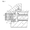
- the bolt 8 can be extended out of the door lock and is sunk with the door closed as shown by the dashed line 10 in a receptacle 11 of the strike plate 5 through a corresponding opening 12.
- the striking plate 5 comprises a cover plate 13 and a housing 11 defining the housing 14 with two side walls 15, to which on the side facing away from the door lock 2, a back plate 16 is screwed.
- Spring-mounted on the rear plate 16 is a contact member 17 is guided in the receptacle.
- the bolt 8 has a bearing surface 18 of the contact member 17 opposite bearing surface 19, wherein there is no direct contact when lowering the bolt 8, as of both contact surfaces 18, 19 spacers, here a spacer bolt 20 and a spacer plate 21, and respectively two in the following figures closer shown contacts 22 and 23, respectively.
- the spacers serve to prevent tilting, since the contacts 22, 23 are arranged at the other end of the contact surface.
- the latch 8 made of metal has a recess into which an insert 25 made of plastic is inserted. From the insert 25, the contacts 22 and two spring contacts 26 protrude on a side surface, shown here only by dashed lines, since they lie in a different plane than the cutting plane. Within the insert 25 extend two electrical lines 27, which form a second line section of a supply line to an indicated at 28 electrical load, here a mechatronic device.
- the spring contacts 26 are moved to two corresponding spring contacts 30 which, like the spring contacts 26, are part of a connection device.
- the resilient contact means of the spring contacts 26, 27 a secure electrical contact is made to the lines 31, which form a third line section of the supply to the load 28.
- FIG. 3 A view of the visible from the outside part of the door lock 2 shows the Fig. 3 in which the bolt 8 with the spacer bolt 20 and the projecting from the insert 25 electrical contacts 22 can be clearly seen.
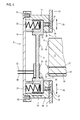
- the Fig. 4 and 5 Now show more views of the striker plate 5 and in particular the contact member 17 in more detail, which is designed as a pick-up shoe with automatic spring.
- the back plate 16 is screwed to the side walls 15 and thus basically removable, see. Screws 32.
- Two springs 33 are supported on the rear plate and form part of a biasing device for the contact member 17, which is thus movable in contact with the latch 8 according to the arrow 34 against a restoring force.
- the bolt 8 If the bolt 8 is now sunk into the receptacle 11, it reaches the contact component with the abutment surface 18, wherein the spacer bolt 20 and the spacer plate 21 and the contacts 22 and 23 come into contact. The bolt 8 extends a little further and thus compresses the springs 33, so that a contact force is created, which ensures the contact.
- the latch 8 is recessed in the striker plate 5
- an electrical connection is made between the first line section formed by the lines 35 and the second line section formed by the lines 27.
- the second line section to the third, leading to the consumer 28 line section formed by the lines 35 is thus the load 28 in a reliable and simple manner connected to the electrical energy source.
- the height of the two contacts 23 of the striking plate 5 can be adjusted in the embodiment shown to be adapted to the height of the contacts 22.
- the side walls 15, which also form a stop 36 for the contact member 17, the rear plate 16 and the contact member 17 form an arrangement which is guided vertically and can be fixed by screws 37 on the cover plate 13.
- the screws engage through elongated holes 38 in the side walls 15, so that when the screws 37 are dissolved, the arrangement is vertically adjustable, as indicated by the arrows 39.
- supply line can also comprise further individual lines, for example for signal transmission.
Landscapes
- Engineering & Computer Science (AREA)
- Computer Security & Cryptography (AREA)
- Lock And Its Accessories (AREA)
Applications Claiming Priority (1)
| Application Number | Priority Date | Filing Date | Title |
|---|---|---|---|
| DE201010019261 DE102010019261A1 (de) | 2010-05-03 | 2010-05-03 | Schließeinrichtung für eine Tür |
Publications (2)
| Publication Number | Publication Date |
|---|---|
| EP2385193A2 true EP2385193A2 (fr) | 2011-11-09 |
| EP2385193A3 EP2385193A3 (fr) | 2012-11-28 |
Family
ID=44483653
Family Applications (1)
| Application Number | Title | Priority Date | Filing Date |
|---|---|---|---|
| EP11164225A Withdrawn EP2385193A3 (fr) | 2010-05-03 | 2011-04-29 | Dispositif de fermeture pour une porte |
Country Status (2)
| Country | Link |
|---|---|
| EP (1) | EP2385193A3 (fr) |
| DE (1) | DE102010019261A1 (fr) |
Cited By (3)
| Publication number | Priority date | Publication date | Assignee | Title |
|---|---|---|---|---|
| EP2597232A3 (fr) * | 2011-11-22 | 2014-10-29 | BKS GmbH | Dispositif de fermeture et de verrouillage avec un boîtier de serrure et une gâche |
| CN107288437A (zh) * | 2017-08-27 | 2017-10-24 | 黎志瀛 | 一种电控门锁供电装置 |
| WO2024163766A1 (fr) * | 2023-02-01 | 2024-08-08 | Janus International Group, Llc | Dispositifs, systèmes et procédés d'accès sécurisé |
Family Cites Families (9)
| Publication number | Priority date | Publication date | Assignee | Title |
|---|---|---|---|---|
| US3966289A (en) * | 1975-05-16 | 1976-06-29 | Schlage Ernest L | Electric power coupler |
| DE4342315A1 (de) * | 1993-04-05 | 1994-10-06 | Erpelding Karl Heinz | Vorrichtung zur Aufnahme von Wertgegenständen o. dgl. |
| DE19521601C1 (de) * | 1995-06-14 | 1996-11-21 | Aubi Baubeschlaege Gmbh | Fenster, Tür oder dergleichen |
| JP3723253B2 (ja) * | 1995-07-01 | 2005-12-07 | 株式会社ゴール | 引戸の給電装置 |
| CN2556322Y (zh) * | 2002-05-17 | 2003-06-18 | 张跃进 | 一种防盗门用电控防盗锁 |
| DE10246669A1 (de) * | 2002-10-07 | 2004-04-15 | Dorma Gmbh + Co. Kg | Türschloss |
| DE202004017953U1 (de) * | 2004-11-18 | 2005-01-20 | Roto Frank Ag | Anordnung zur elektrischen Anspeisung von Verschlussantrieben |
| DE102006000280A1 (de) * | 2006-06-09 | 2007-12-13 | Aug. Winkhaus Gmbh & Co. Kg | Verschluss für einen Treibstangenbeschlag und Treibstangenbeschlag mit einem solchen Verschluss |
| AU2007278811B2 (en) * | 2006-07-27 | 2011-10-13 | Gainsborough Hardware Industries Limited | A lock arrangement and a method of providing power to a lock |
-
2010
- 2010-05-03 DE DE201010019261 patent/DE102010019261A1/de not_active Withdrawn
-
2011
- 2011-04-29 EP EP11164225A patent/EP2385193A3/fr not_active Withdrawn
Non-Patent Citations (1)
| Title |
|---|
| None |
Cited By (3)
| Publication number | Priority date | Publication date | Assignee | Title |
|---|---|---|---|---|
| EP2597232A3 (fr) * | 2011-11-22 | 2014-10-29 | BKS GmbH | Dispositif de fermeture et de verrouillage avec un boîtier de serrure et une gâche |
| CN107288437A (zh) * | 2017-08-27 | 2017-10-24 | 黎志瀛 | 一种电控门锁供电装置 |
| WO2024163766A1 (fr) * | 2023-02-01 | 2024-08-08 | Janus International Group, Llc | Dispositifs, systèmes et procédés d'accès sécurisé |
Also Published As
| Publication number | Publication date |
|---|---|
| EP2385193A3 (fr) | 2012-11-28 |
| DE102010019261A1 (de) | 2011-11-03 |
Similar Documents
| Publication | Publication Date | Title |
|---|---|---|
| DE112007001299B4 (de) | Nockenschloss mit rückziehbarem Dorn | |
| EP2211004A1 (fr) | Dispositif de verrouillage | |
| WO2009036585A1 (fr) | Dispositif de verrouillage | |
| EP3132717A1 (fr) | Dispositif destine a deplacer un element mobile de meuble | |
| DE102015117509A1 (de) | Steckverbinderteil mit einem Verriegelungselement | |
| DE102016125888A1 (de) | Rahmen-Überwachungsvorrichtung für Fenster oder Türen und Fenster oder Tür mit Rahmen-Überwachungsvorrichtung | |
| EP2685032B1 (fr) | Unité de fermeture électronique pour l'armoire d'une installation de fermeture multiple | |
| EP2998487B1 (fr) | Serrure et systeme de fermeture electronique | |
| EP2385193A2 (fr) | Dispositif de fermeture pour une porte | |
| EP1256671A2 (fr) | Rosette pour serrure cylindrique | |
| DE102014104128B4 (de) | Zuhaltung | |
| EP2711490B1 (fr) | Dispositif de déplacement d'un corps mobile de manière translatoire et serrure avec un verrou | |
| EP1736622A1 (fr) | Barrilet à bouton | |
| DE202011105510U1 (de) | Türöffner mit Sperr-Riegel | |
| DE202009010618U1 (de) | Schlossanordnung einer Tür, eines Fensters o.dgl. sowie Tür, Fenster o.dgl. mit einer Schlossanordnung | |
| EP3516138A1 (fr) | Serrure de porte | |
| CH715020B1 (de) | Schloss, Beschlag, Schliessblech und Schliessvorrichtung für Schiebetüren sowie Schiebetüranlage. | |
| AT8882U1 (de) | Vorrichtung zum öffnen und schliessen eines bewegbaren möbelteils od. dgl. | |
| DE202010011972U1 (de) | Einrichtung zum Sichern der Schließstellung eines beweglich an einem Möbelrahmen angeordneten Schließelementes | |
| DE202018105006U1 (de) | Stößelkontakteinheit | |
| DE102013012203A1 (de) | Elektrischer Türöffner sowie ein Passivflügelschloss mit einem solchen Türöffner | |
| DE102014112050B4 (de) | Baukastensystem einer Schließvorrichtung eines Gebäudes | |
| WO2016012462A1 (fr) | Système de fermeture électronique | |
| EP2293085A1 (fr) | Appareil de mesure | |
| EP3293329B1 (fr) | Loqueteau de porte d'armoire doté de module d'émission-réception |
Legal Events
| Date | Code | Title | Description |
|---|---|---|---|
| AK | Designated contracting states |
Kind code of ref document: A2 Designated state(s): AL AT BE BG CH CY CZ DE DK EE ES FI FR GB GR HR HU IE IS IT LI LT LU LV MC MK MT NL NO PL PT RO RS SE SI SK SM TR |
|
| AX | Request for extension of the european patent |
Extension state: BA ME |
|
| PUAI | Public reference made under article 153(3) epc to a published international application that has entered the european phase |
Free format text: ORIGINAL CODE: 0009012 |
|
| PUAL | Search report despatched |
Free format text: ORIGINAL CODE: 0009013 |
|
| AK | Designated contracting states |
Kind code of ref document: A3 Designated state(s): AL AT BE BG CH CY CZ DE DK EE ES FI FR GB GR HR HU IE IS IT LI LT LU LV MC MK MT NL NO PL PT RO RS SE SI SK SM TR |
|
| AX | Request for extension of the european patent |
Extension state: BA ME |
|
| RIC1 | Information provided on ipc code assigned before grant |
Ipc: E05B 15/02 20060101ALI20121024BHEP Ipc: E05B 47/02 20060101AFI20121024BHEP Ipc: E05B 15/10 20060101ALI20121024BHEP |
|
| STAA | Information on the status of an ep patent application or granted ep patent |
Free format text: STATUS: THE APPLICATION IS DEEMED TO BE WITHDRAWN |
|
| 18D | Application deemed to be withdrawn |
Effective date: 20130529 |