EP2385249A1 - Windradschaufel und windgetriebene stromerzeugungsvorrichtung damit - Google Patents
Windradschaufel und windgetriebene stromerzeugungsvorrichtung damit Download PDFInfo
- Publication number
- EP2385249A1 EP2385249A1 EP10825826A EP10825826A EP2385249A1 EP 2385249 A1 EP2385249 A1 EP 2385249A1 EP 10825826 A EP10825826 A EP 10825826A EP 10825826 A EP10825826 A EP 10825826A EP 2385249 A1 EP2385249 A1 EP 2385249A1
- Authority
- EP
- European Patent Office
- Prior art keywords
- blade
- reinforcing section
- outer shell
- downwind
- upwind
- Prior art date
- Legal status (The legal status is an assumption and is not a legal conclusion. Google has not performed a legal analysis and makes no representation as to the accuracy of the status listed.)
- Withdrawn
Links
Images


Classifications
-
- F—MECHANICAL ENGINEERING; LIGHTING; HEATING; WEAPONS; BLASTING
- F03—MACHINES OR ENGINES FOR LIQUIDS; WIND, SPRING, OR WEIGHT MOTORS; PRODUCING MECHANICAL POWER OR A REACTIVE PROPULSIVE THRUST, NOT OTHERWISE PROVIDED FOR
- F03D—WIND MOTORS
- F03D1/00—Wind motors with rotation axis substantially parallel to the air flow entering the rotor
- F03D1/06—Rotors
- F03D1/065—Rotors characterised by their construction elements
- F03D1/0675—Rotors characterised by their construction elements of the blades
-
- B—PERFORMING OPERATIONS; TRANSPORTING
- B29—WORKING OF PLASTICS; WORKING OF SUBSTANCES IN A PLASTIC STATE IN GENERAL
- B29L—INDEXING SCHEME ASSOCIATED WITH SUBCLASS B29C, RELATING TO PARTICULAR ARTICLES
- B29L2031/00—Other particular articles
- B29L2031/08—Blades for rotors, stators, fans, turbines or the like, e.g. screw propellers
- B29L2031/082—Blades, e.g. for helicopters
- B29L2031/085—Wind turbine blades
-
- F—MECHANICAL ENGINEERING; LIGHTING; HEATING; WEAPONS; BLASTING
- F05—INDEXING SCHEMES RELATING TO ENGINES OR PUMPS IN VARIOUS SUBCLASSES OF CLASSES F01-F04
- F05B—INDEXING SCHEME RELATING TO WIND, SPRING, WEIGHT, INERTIA OR LIKE MOTORS, TO MACHINES OR ENGINES FOR LIQUIDS COVERED BY SUBCLASSES F03B, F03D AND F03G
- F05B2240/00—Components
- F05B2240/20—Rotors
- F05B2240/21—Rotors for wind turbines
- F05B2240/221—Rotors for wind turbines with horizontal axis
-
- F—MECHANICAL ENGINEERING; LIGHTING; HEATING; WEAPONS; BLASTING
- F05—INDEXING SCHEMES RELATING TO ENGINES OR PUMPS IN VARIOUS SUBCLASSES OF CLASSES F01-F04
- F05B—INDEXING SCHEME RELATING TO WIND, SPRING, WEIGHT, INERTIA OR LIKE MOTORS, TO MACHINES OR ENGINES FOR LIQUIDS COVERED BY SUBCLASSES F03B, F03D AND F03G
- F05B2240/00—Components
- F05B2240/20—Rotors
- F05B2240/30—Characteristics of rotor blades, i.e. of any element transforming dynamic fluid energy to or from rotational energy and being attached to a rotor
-
- F—MECHANICAL ENGINEERING; LIGHTING; HEATING; WEAPONS; BLASTING
- F05—INDEXING SCHEMES RELATING TO ENGINES OR PUMPS IN VARIOUS SUBCLASSES OF CLASSES F01-F04
- F05B—INDEXING SCHEME RELATING TO WIND, SPRING, WEIGHT, INERTIA OR LIKE MOTORS, TO MACHINES OR ENGINES FOR LIQUIDS COVERED BY SUBCLASSES F03B, F03D AND F03G
- F05B2280/00—Materials; Properties thereof
- F05B2280/60—Properties or characteristics given to material by treatment or manufacturing
- F05B2280/6003—Composites; e.g. fibre-reinforced
-
- Y—GENERAL TAGGING OF NEW TECHNOLOGICAL DEVELOPMENTS; GENERAL TAGGING OF CROSS-SECTIONAL TECHNOLOGIES SPANNING OVER SEVERAL SECTIONS OF THE IPC; TECHNICAL SUBJECTS COVERED BY FORMER USPC CROSS-REFERENCE ART COLLECTIONS [XRACs] AND DIGESTS
- Y02—TECHNOLOGIES OR APPLICATIONS FOR MITIGATION OR ADAPTATION AGAINST CLIMATE CHANGE
- Y02E—REDUCTION OF GREENHOUSE GAS [GHG] EMISSIONS, RELATED TO ENERGY GENERATION, TRANSMISSION OR DISTRIBUTION
- Y02E10/00—Energy generation through renewable energy sources
- Y02E10/70—Wind energy
- Y02E10/72—Wind turbines with rotation axis in wind direction
-
- Y—GENERAL TAGGING OF NEW TECHNOLOGICAL DEVELOPMENTS; GENERAL TAGGING OF CROSS-SECTIONAL TECHNOLOGIES SPANNING OVER SEVERAL SECTIONS OF THE IPC; TECHNICAL SUBJECTS COVERED BY FORMER USPC CROSS-REFERENCE ART COLLECTIONS [XRACs] AND DIGESTS
- Y02—TECHNOLOGIES OR APPLICATIONS FOR MITIGATION OR ADAPTATION AGAINST CLIMATE CHANGE
- Y02P—CLIMATE CHANGE MITIGATION TECHNOLOGIES IN THE PRODUCTION OR PROCESSING OF GOODS
- Y02P70/00—Climate change mitigation technologies in the production process for final industrial or consumer products
- Y02P70/50—Manufacturing or production processes characterised by the final manufactured product
Definitions
- the present invention relates to a wind turbine blade and a wind turbine generator using the wind turbine blade.
- FIG.1A is a sectional view schematically illustrating a structure of a wind turbine blade.
- the blade 100 comprises an outer shell 101 having a basic laminated structure, a leading edge reinforcing section 103 having a reinforced laminated structure, a trailing edge reinforcing section 105 (105a, 105b), an upwind-side reinforcing section 104a, a downwind-side reinforcing section 104b and a beam member 102.
- the leading edge reinforcing section 103, the trailing edge reinforcing section 105, the upwind-side reinforcing section 104a and the downwind-side reinforcing section 104b are arranged respectively in a leading part, a trailing part, a upwind-side part and a downwind-side part of the wind turbine blade 100.
- the blade is constructed such that unidirectional reinforcing material of fiber-reinforced plastic is arranged in a location far from a flexural center X.
- the unidirectional reinforcing material is also referred to as PUD material or 0° material.
- UD material is intensively laminated in a center of the upwind-side and the downwind-side (the upwind-side reinforcing section 104a and the downwind-side reinforcing section 104b) and the leading edge part and trailing edge part (the leading edge reinforcing section 103 and the trailing edge reinforcing section 105a, 105b).
- the outer shell covering the entire surface of the blade 100 can be made of bias materials having plural layers of fiber-reinforced plastic ( ⁇ 45° material or multi-directional material).
- the part in which UD material is not laminated (the parts other than the leading reinforcing section 103, the trailing edge reinforcing section 105a, 105b, the upwind-side reinforcing section 104a and the downwind-side reinforcing section 104b) has a structure such as a sandwich structure wherein, for instance, a core material is interposed between plural layers of bias materials.
- FIG.1B is a pattern diagram illustrating the laminated structure of FIG.1A in detailed.
- a solid line indicates a bias material( ⁇ 45° material) 111
- a dotted line indicates UD material (0° material) 112
- a trapezoid indicates a core material 113.
- n layers of ⁇ 45° material are provided on its outer side and m layers of ⁇ 45° material are provided on its inner side.
- "n" and "m” are both natural numbers.
- the following layers are provided between the n layers of ⁇ 45° material and the m layers of ⁇ 45° material.
- p layers of 0° material are provided between the n layers of ⁇ 45° material and the m layers of ⁇ 45° material in the leading edge reinforcing section 103; q layers of 0° material are provided between the n layers of ⁇ 45° material and the m layers of ⁇ 45° material in the upwind-side reinforcing section 104a/the downwind-side reinforcing section 104b; r layers of 0° material are provided between the n layers of ⁇ 45° material and the m layers of ⁇ 45° material in the trailing edge reinforcing section 105a/105b.
- "p", "q” and “r” are all natural numbers. In this case, the inequality of q >> q, r exists.
- a single layer of core material 113 is provided. Further, the trailing tip (most outer edge) may be covered solely by the outer shell 101 (including the core material 113).
- 0° material is a material whose resin is arranged 0° with respect to a longitudinal direction of the wind turbine blade. In the material, resin is penetrated.
- the material may be fiber-reinforced plastic whose fibers are laminated 0° with respect the longitudinal direction of the blade.
- ⁇ 45° material may be a material whose fibers are laminated one atop another in different directions +45° and -45° with respect to the longitudinal direction of the wind turbine blade.
- resin is penetrated.
- the material may be fiber-reinforced plastic whose fibers are arranged ⁇ 45° with respect to the longitudinal direction of the blade.
- the fiber is, for instance, carbon fiber, glass fiber and so on.
- the leading edge reinforcing section 103 has the laminated structure having ( ⁇ 45°) n /(0° ) p /( ⁇ 45°) m in this order from the outer side to the inner side.
- the upwind-side reinforcing section 104a and the downwind-side reinforcing section 104b has the laminated structure having ( ⁇ 45°) n /(0° ) q /( ⁇ 45°) m in this order from the outer side to the inner side.
- the trailing edge reinforcing section 105a/105b has the laminated structure having ( ⁇ 45°) n 1(0° ) r /( ⁇ 45°) m in this order from the outer side to the inner side.
- the rest has the laminated structure having ( ⁇ 45°) n / core material /( ⁇ 45°) m in this order from the outer side to the inner side.
- " ⁇ 45°” and “0°” indicate ⁇ 45° material and 0° material respectively and
- "n", "m”, “p”, “q” and “r” respective indicate the number of layers.
- JP2006-118434A discloses a production method of a lightweight wind turbine blade.
- the wind turbine blade is used for a vertical axis wind turbine generator.
- the wind turbine blade is configured such that a first half divided blade and a second half divided blade including wind turbine blade surface layers is laminated and formed by impregnating predetermined fiber material with resin material for lamination mixed with curing agent to form a predetermined space in a wind mill.
- a blade support layer supporting in a thickness direction in the blade is laminated and formed on circumference surface of an elastic cylindrical member by impregnating a predetermined fiber member with resin maternal.
- the cylindrical member is arranged at a predetermined position in a blade longitudinal direction in the blade to press an in-blade support layer against the first half divided blade and the second half divided blade respectively by elastic force in the blade to form the in-blade support layer as one unit with the first half divided blade and the second half divided blade and the first half divided blade and the second half divided blade are coupled and are left as they are for a predetermined period of time.
- a wind turbine blade is formed by integration of all of the first half divided blade, the second half divided blade and the in-blade support layer by curing action of curing agent.
- JP6-66244A disposes a wind turbine blade.
- the wind turbine blade has a main girder arranged in a longitudinal direction of an outer shell to enhance the strength.
- plural layers of unidirectional roving cloth are stacked one atop another along the longitudinal direction of the main girder, and normal glass cloth and a glass mat are stacked over the stack of layers of roving cloth into the shape of a bondage using the tape winding method.
- the UD material 112 needs to be laminated on the leading edge part (the leading edge reinforcing section 103) and the trailing edge part (the trailing edge reinforcing section 105) as well as the upwind side part (the upwind-side reinforcing section 104a) and the downwind-side part (the downwind-side reinforcing section 104b).
- the UD material 112 needs to be laminated, which takes time and thus, the time for manufacturing is long. Further, the places near the blade root have an almost cylindrical shape as shown in FIG.3 .
- the UD material when laminating the UD material on the leading edge part (the leading edge reinforcing section 103) and the trailing edge part (the trailing edge reinforcing section 105), the UD material needs to be adhered on surfaces that are almost vertical. As a result, the UD material tends to droop down and it becomes difficult to manufacture the blade,
- a wind turbine blade of one aspect of the present invention has a laminated structure.
- the laminated structure may include, but is not limited to, an outer shell (1) having a shape of the blade, an upwind-side reinforcing section (4a) which reinforces a upwind-side part of the blade in the outer shell (1) and a downwind-side reinforcing section (4b) which reinforces a downwind-side part of the blade in the outer shell (1).
- the outer shell (1) may include, but is not limited to, a first multidirectional material (11:( ⁇ 45°) n ), a first unidirectional reinforcing material (12:(0°) n ) and a second multidirectional material (11:( ⁇ 45°) m ).
- the upwind-side reinforcing section (4a) may include, but is not limited to, a second unidirectional reinforcing material (12:(0°) Q ) provided between the first unidirectional reinforcing material (12:(0°) N ) and the second multidirectional material (11:( ⁇ 45°) m ).
- the downwind-side reinforcing section (4b) may include, but is not limited to, a third unidirectional reinforcing material (12:(0°) Q ) provided between the first unidirectional reinforcing material (12:(0°) N ) and the second multidirectional material(11:( ⁇ 45°) m ).
- the outer shell (1) may include, but is not limited to, a first core member (13) respectively provided between the upwind-side reinforcing section (4a) and the downwind-side reinforcing section (4b) on a leading edge side, and between the upwind-side reinforcing section (4a) and the downwind-side reinforcing section (4b) on a trailing edge side.
- the bending rigidity required for the blade is achieved by laminating the unidirectional reinforcing material (12:(0°) N ) on the outer shell (1) of the entire blade surface and providing the upwind-side reinforcing section (4a) and the downwind-side reinforcing section (4b).
- the unidirectional reinforcing material (12:(0°) N ) on the outer shell (1) of the entire blade surface and providing the upwind-side reinforcing section (4a) and the downwind-side reinforcing section (4b).
- the weight decrease from skipping the unidirectional reinforcing material in the leading edge part and the trailing edge part can counteract the weight increase from using the unidirectional reinforcing material (12:(0°) N ) in the outer shell (1) of the entire blade surface.
- the required rigidity of the blade can be obtained while maintaining the lightweight of the blade by suppressing the weight increase of the whole wind turbine blade.
- a trailing edge reinforcing section (5a) that reinforces a trailing edge part of the blade in the outer shell (1) is also provided.
- the trailing edge reinforcing section (5a) may include, but is not limited to, a fourth unidirectional reinforcing material (12:(0°) Q ) arranged between the first unidirectional reinforcing material (12:(0°) N ) and the second multidirectional material (11:( ⁇ 45°) m ).
- the outer shell (1) may include, but is not limited to, the first core member (13) respectively provided between the upwind-side reinforcing section (4a) and the downwind-side reinforcing section (4b) on the leading edge side, between the upwind-side reinforcing section (4a) and the trailing edge reinforcing section (5a), and between the downwind-side reinforcing section (4b) and the trailing edge reinforcing section (5b).
- the bending rigidity required for the blade is achieved by providing the trailing edge reinforcing sections (5a, 5b) as well. Thus, it is not necessary to provide the reinforcing sections using the unidirectional reinforcing material in the leading edge part.
- the number of places where the UD material is provided can be reduced in the manufacturing process and also the time for the laminating process can be shortened in comparison to the conventional case.
- a UD material for the leading edge part is not provided in the blade, it is possible to solve the issue that the manufacturing is difficult near the blade root where the shape of the blade is almost cylindrical, which causes the UD material to droop down.
- the weight decrease from not using the unidirectional reinforcing material in the leading edge part can counteract the weight increase from using the unidirectional reinforcing material in the outer shell (1) of the entire blade surface (although not as much as the case of not having the trailing edge reinforcing sections 5a, 5b).
- the required rigidity of the blade can be obtained while maintaining the lightweight of the blade by suppressing the weight increase of the whole wind turbine blade.
- the outer shell (1) may also include, but is not limited to, a fifth unidirectional reinforcing material (12:(0°) M ).
- the fifth unidirectional reinforcing material (12:(0°) M ) is provided on an inner side of the second multidirectional material (11:( ⁇ 45°) m ) so as to be layered on the second multidirectional material (11:( ⁇ 45°) m ).
- the unidirectional reinforcing material (12:(0°) M ) is added on the outer shell (1) of the entire blade surface and thus, the bending rigidity can be enhanced.
- the blade has the laminated structure from a root of the blade to vicinity of a maximum chord location at which a chord is maximum (Sl) and has other laminated structure from the maximum chord location to a tip of the blade (S2).
- the laminated structure (in S2) from the maximum chord location to the tip of the blade may include, but is not limited to other outer shell (101) having a shape of the blade, other upwind-side reinforcing section (104a) which reinforces the upwind-side part of the blade in said other outer shell, other downwind-side reinforcing section (104b) which reinforces the downwind-side part of the blade in the outer shell (101), other leading edge reinforcing section (103) which reinforces the leading edge part of the blade in the outer shell (101) and other trailing edge reinforcing section (105) which reinforces the trailing edge part of the blade in the outer shell (101).
- the outer shell (101) may include, but is not limited to, the first multidirectional material (111:( ⁇ 45°) N ) and the second multidirectional material (111:( ⁇ 45°) m ) which are layered.
- the upwind-side reinforcing section (104a) may include, but is not limited to, a sixth unidirectional reinforcing material (l12:(0°) q ) provided between the first multidirectional material (111:( ⁇ 45°) n ) and the second multidirectional material (111:( ⁇ 45°) m ).
- the downwind-side reinforcing section (104b) may include, but is not limited to, a seventh unidirectional reinforcing material (112:(0°) q ) provided between the first multidirectional material (111:( ⁇ 45°) n ) and the second multidirectional material (111:( ⁇ 45°) m ).
- the leading edge reinforcing section (103) may include, but is not limited to, an eighth unidirectional reinforcing (111:(0°) p ) material provided between the first multidirectional material (111:( ⁇ 45°) n ) and the second multidirectional material (111:( ⁇ 45°) m ).
- the trailing edge reinforcing section may includes, but is not limited to, a ninth unidirectional reinforcing material (111:(0°) r ) the first multidirectional (111:( ⁇ 45°) n ) and the second multidirectional material (111:( ⁇ 45°) m ).
- the outer shell (101) may include, but is not limited to, a second core member (113) respectively provided between the upwind-side reinforcing section (104a) and the leading edge reinforcing section (103), between the upwind-side reinforcing section (104a) and the trailing edge reinforcing section (105), between the downwind-side reinforcing section (104b) and the leading edge reinforcing section (103), and between the downwind-side reinforcing section (104b) and the trailing edge reinforcing section (105).
- a second core member (113) respectively provided between the upwind-side reinforcing section (104a) and the leading edge reinforcing section (103), between the upwind-side reinforcing section (104a) and the trailing edge reinforcing section (105), between the downwind-side reinforcing section (104b) and the leading edge reinforcing section (103), and between the downwind-side reinforcing section (104b) and the trailing edge reinforcing
- the bending rigidity of the blade can be attained by providing, from the maximum chord location to the tip of the blade (in S2), the downwind-side reinforcing section (104b), the leading edge reinforcing section (103) and the trailing edge reinforcing section (105) without using the unidirectional reinforcing material in the outer shell (101) of the entire blade surface.
- the wind turbine blade can be lighter in comparison to the case of laminating the unidirectional reinforcing material on the entire blade surface.
- FIG. 1 Another aspect of the present invention is a wind turbine generator having a rotor head supported rotatably with respect to a nacelle and a wind turbine blade which is mounted on a rotor head.
- a wind turbine rotor is constituted of the rotor head and the wind turbine blade and the turbine rotor is rotated by a wind force and rotation energy of the turbine rotor is converted to power generation energy.
- the wind turbine blade has the above-mentioned technical features, it is possible to achieve the high bending rigidity and the shorter manufacturing time and the ease of the manufacturing as described before.
- the present invention it is possible to provide a wind turbine blade and a wind turbine generator using the wind turbine blade that achieve a shorter manufacturing time and ease of the manufacturing. It is also possible to provide a wind turbine blade and a wind turbine generator using the wind turbine blade that achieve a shorter manufacturing time and ease of the manufacturing while preventing the weight increase of the blade.
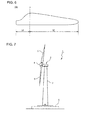
- FIG.7 is a side-view showing a structure of a wind turbine generator 1 which uses the wind turbine blade of preferred embodiments of the present invention.
- the wind turbine generator 1 includes a support 2 standing upright from a base 6, a nacelle 3 mounted on the top of the baste 2, a rotor head mounted rotatably with respect to the nacelle 3 and blades 5 mounted on the rotor head 4.
- the rotor head and the blades 5 constitute a wind turbine rotor.
- FIG.4A is a schematic view showing a structure of the wind turbine blade in rotation to the first preferred embodiment of the present invention.
- This wind turbine blade 10 has an outer shell 1 of a basic laminated structure, an upwind-side reinforcing section 4a and a downwind-side reinforcing section 4b.
- the upwind-side reinforcing section 4a and the downwind-side reinforcing section 4b have a reinforced laminated structure.
- the upwind-side reinforcing section 4a and the downwind-side reinforcing section 4b are provided in an upwind-side part and a downwind-side part of the wind turbine blade 10 respectively.
- a structure having a fiber-reinforced plastic of unidirectional reinforcing material 12 (UD material or 0° material) arranged in a location far from a flexural center X is popular to make a lighter blade 10 while maintaining the bending rigidity required for the blade.
- the UD material 12 is layered in the outer shell 1 as well.
- the UD material 12 is disposed on the upwind-side part and the downwind-side part of the blade (the upwind-side reinforcing section 4a and the downwind-side reinforcing section 4b) to be layered intensively while it is not necessary to provide the UD material 12 on the leading edge part and the trailing edge part. This structure is described below in detail.
- the outer shell 1 includes bias materials 11 (referred to as ⁇ 45° material or multi-directional material) which is a multi-layer of fiber-reinforced plastic, of which a blade surface of the wind turbine blade 10 is made, or the like.
- bias materials 11 referred to as ⁇ 45° material or multi-directional material
- the parts in which the UD material 12 is not provided have a structure such as a sandwich structure wherein, for instance, a core material 13 is interposed between plural layers of the bias materials 11.
- FIG.4B is a schematic view showing the laminated structure of FIG.4A .
- the solid line indicates the bias material ( ⁇ 45° material)
- the dotted line indicates the UD maternal 12 (0° material)
- the trapezoid indicates a core material 13.
- n layers of ⁇ 45° material, N1 layers of 0° material, M1 layers of 0° material, m layers of ⁇ 45° material are respectively arranged in this order from the outer side to the inner side of the outer shell 1.
- n", “m”, “N1” and “M1” are all natural numbers (positive integer numbers) and the inequalities of N1 + M1 ⁇ 1, N1 ⁇ 1, M1 ⁇ 0 exist.
- the layers as described below are provided between the N1 layers of 0° material and the M1 layers of 0° material.
- Q1 layers of 0° material are provided between the N1 layers of 0° material and the M1 layers of 0° material in the upwind-side reinforcing section 4a/downwind-side reinforcing section 4b ("Q" is a natural number). In this case, "Q1" is smaller than "q” (see FIG.1B ).
- the bending rigidity is improved by using 0° material in the outer shell 1. In the remaining part, a single layer of core material 13 is provided. In consideration of the required rigidity, the number of layers (Q1) may be different in the upwind-side reinforcing section 4a and the downwind-side reinforcing section respectively.
- 0° material (UD material) 12 and ⁇ 45° material (bias material) 11 are the UD material 112 and the bias material 111 aforementioned in reference to FIG.2 .
- the upwind-side reinforcing section 4a / the downwind-side reinforcing section 4b has the laminated structure having ( ⁇ 45°) n /(0° ) N1 /(0° ) Q1 /(0° ) M1 / ( ⁇ 45°) m in this order from the outer side to the inner side.
- the other parts has the laminated structure having ( ⁇ 45°) n ) /(0° ) N1 / core material / (0° ) M1 / ( ⁇ 45°) m in this order from the outer side to the inner side.
- " ⁇ 45°” and “0°” respectively indicate ⁇ 45° material and 0° material and "n", "m", “Nl”, "Q1" and "M1" respective indicate the number of layers.
- the number of layers (N1 layers) of the UD material to be layered on the whole outer shell is the smallest number that can attain the bending rigidity required for the blade without the UD material for reinforcing the leading edge part and the trailing edge part being provided. This smallest number of layers can be determined by methods such as tests and simulations. In this manner, the number of layers af the UD material ta be layered on the whole outer shell is set as small as possible so as to prevent the weight increase of the blade.
- the bending rigidity required for the blade is achieved by laminating the unidirectional reinforcing 0° material (UD material) on the outer shell of the whole blade surface.
- UD material unidirectional reinforcing 0° material
- the structure in which the leading edge part and the trailing edge part are not laminated intensively with the UD material can be achieved.
- the number of places where the UD material is provided can be reduced in the manufacturing process and also the time for the laminating process can be shortened in comparison to the conventional case.
- a UD material for the leading edge part and the trailing edge part is not provided in the blade, it is possible to solve the issue that the manufacturing is difficult near the blade root where the shape of the blade is almost cylindrical, which causes the UD material to droop down.
- the upwind-side part and the downwind-side part are intensively laminated with the UD material while the leading edge part and the trailing edge part is not intensively laminated with the UD material.
- the UD material is provided in the outer shell and also intensively provided in the upwind-side part and the downwind-side part, and thus the amount of the UD material to be used additionally can be suppressed and the blade can remain light and still possess the required bending rigidity.
- FIG.5A is a sectional view schematically showing a structure of a wind turbine blade in relation to the second preferred embodiment of the present invention.
- the wind turbine blade 10a has an outer shell 1 of a basic laminated structure, an upwind-side reinforcing section 4a, a downwind-side reinforcing section 4b, and trailing edge reinforcing sections 5a, 5b.
- the upwind-side reinforcing section 4a, the downwind-side reinforcing section 4b and the trailing edge reinforcing sections 5a, 5b have a reinforced laminated structure.
- the upwind-side reinforcing section 4a, the downwind-side reinforcing section 4b and the trailing edge reinforcing sections 5a, 5b are provided in the upwind-side part, the downwind-side and the leading edge part of the wind turbine blade 10 respectively.
- the second preferred embodiment is different from the first preferred embodiment in that the UD material 12 of the fiber-reinforced plastic is intensively provided not only on the upwind side (the upwind-side reinforcing section 4a) and the downwind side (the downwind-side reinforcing section 4b) but also on the leading edge side (the leading edge reinforcing sections 5a, 5b).
- the additional UD material 12 is intensively laminated on the upwind side (the upwind-side reinforcing section 4a), the downwind side (the downwind-side reinforcing section 4b) and the leading edge side (the leading edge reinforcing sections 5a, 5b) but not on the leading edge part,
- the reason that UD material is provided in the trailing edge part instead of the leading edge part is that the UD material is to be disposed far from the flexural center X to reduce the weight of the blade while maintaining the bending rigidity. This is further explained below in detail.
- the outer shell 1 includes bias materials 11 (referred to as ⁇ 45° material or multi-directional material) which is a multi-layer of fiber-reinforced plastic, of which a blade surface of the wind turbine blade 10 is made, or the like.
- bias materials 11 referred to as ⁇ 45° material or multi-directional material
- the parts in which the UD material 12 is not provided have a structure such as a sandwich structure wherein, for instance, a core material 13 is interposed between plural layers of the bias materials 11.
- FIG.5B is a schematic view showing the laminated structure of FIG.5A .
- the solid line indicates the bias material ( ⁇ 45° material)
- the dotted line indicates the UD material 12 (0° material)
- the trapezoid indicates the core material 13.
- n layers of ⁇ 45° material, N2 layers of 0° material, M2 layers of 0° material, m layers of ⁇ 45° material are respectively arranged in this order from the outer side to the inner side of the outer shell 1.
- n, "m”, “N2” and “M2” are all natural numbers and inequalities of N2 + M2 ⁇ 1, N2 ⁇ 1, M2 ⁇ 0 exist.
- the layers as described below are provided between the N2 layers of 0° material and the M2 layers of 0° material.
- Q2 layers of 0° material are provided in the upwind-side reinforcing section 4a/downwind-side reinforcing section 4b ("Q2" is a natural number) and R layers of 0° material are provided in the trailing edge reinforcing sections 5a, 5b ("R2" is a natural number).
- Q2 ⁇ q see FIG.1B
- R ⁇ r see FIG.1B
- the bending rigidity is improved by using 0° material in the outer shell 1. It is also possible to achieve M2 ⁇ M1, N2 ⁇ N1 and Q2 ⁇ Q1 (see FIG.4B ).
- the bending rigidity is enhanced by providing the trailing edge reinforcing sections 5a, 5b.
- a single layer of core material 13 is provided.
- the number of layers (Q2) may be different in the upwind-side reinforcing section 4a and the downwind-side reinforcing section respectively.
- the number of layers (R) may be different in each of the trailing edge reinforcing sections 5a and 5b respectively.
- 0° material (UD material) 12 and ⁇ 45° material (bias material) 11 are the UD material 112 and the bias material 111 aforementioned in reference to FIG.2 .
- the upwind-side reinforcing section 4a / the downwind-side reinforcing section 4b have the laminated structure having ( ⁇ 45°) n /(0° ) N2 /(0° ) Q2 /(0° ) M2 / (+45°) m in this order from the outer side to the inner side.
- the railing edge reinforcing sections 5a, 5b have the laminated structure having ( ⁇ 45°) n /(0° ) N2 /(0° ) R /(0° ) M2 / (+45°) m in this order from the outer side to the inner side.
- the other parts have the laminated structure having ( ⁇ 45°) n /(0° ) N2 / core material / (0° ) M2 / ( ⁇ 45o) m in this order from the outer side to the inner side.
- " ⁇ 45°” and “0°” respectively indicate ⁇ 45° material and 0° material and "n", “m”, “N2", “Q2", “R” and “M2” respective indicate the number of layers.
- a trailing tip of the trailing edge part may have only the outer shell 101 (including the core material 13).
- the number of layers (N2 layers) of the UD material to be layered on the whole outer shell is the smallest number of layers that can achieve the bending rigidity required for the blade without the UD material for the leading edge part being provided. This smallest number of layers can be determined by methods such as a test and a simulation. In this manner, the number of layers of the UD material to be layered on the whole outer shell is set as small as possible so as to suppress the weight increase of the blade.
- the bending rigidity required for the blade is achieved by laminating the unidirectional reinforcing 0° material (UD material) on the outer shelf of the whole blade surface.
- UD material unidirectional reinforcing 0° material
- the structure in which the leading edge part is not laminated intensively with the UD material can be achieved.
- the number of places where the UD material is provided can be reduced in the manufacturing process and also the time for the laminating process can be shortened in comparison to the conventional case.
- a UD material for the leading edge part is not provided in the blade, it is possible to solve the issue that the manufacturing is difficult near the blade root where the shape of the blade is almost cylindrical causing the UD material to droop down.
- the upwind-side part, the downwind-side part and the trailing edge part are intensively laminated with the UD material while the leading edge part is not intensively laminated with the UD material.
- the UD material is provided in the outer shell and also intensively provided in the upwind-side part, the downwind-side part and the trailing edge part and thus the amount of the UD material to be needed additionally can be suppressed and the blade can remain light weight and still possess the required bending rigidity.
- the second preferred embodiment is different from the first preferred embodiment in that the UD material is intensively provided in the trailing edge part as well, thereby reducing the amount of the UD material to be used in the outer shell. As a result, the amount of the UD material to be needed can be suppressed and the blade can remain lightweight and still possess the required bending rigidity.
- FIG.6 is a sectional view schematically showing a structure of a wind turbine blade in relation to the third preferred embodiment of the present invention.
- This wind turbine blade 10b has a blade root section S1 and a main section S2.
- the blade root section S1 from the root to vicinity of a maximum chord location of the blade, and the main section S2 from the maximum chord location to a tip of the blade have different laminated structures. This is different from the first and second preferred embodiments. The above structure is described in detailed below.
- the blade root section S1 is near the blade root and has an almost cylindrical shape, which causes the UD material to droop down.
- the laminated structure of the first preferred embodiment (see FIG.4A and Fig.4B ) is used in the blade root section S1.
- the UD material 12 is laminated on the entire blade surface and the additional UD material 12 for the leading edge part and the trailing edge part is not provided.
- the laminated structure of the second preferred embodiment may be applied to the blade root section S1.
- the main section S2 has the laminated structure of the related art ( FIG.1A and FIG.IB). Specifically, in the main section S2 from the maximum chord location to the tip of the blade, the UD material 12 for the entire blade surface is not provided, and instead the UD material 12 is intensively provided in the leading edge part, the trailing edge part, the upwind part and the downwind part. As a result, in comparison to the case of laminating the UD material on the entire blade surface, the amount of the UD material to be used is minimized and thus, the weight of the blade ean be reduced more. Alternatively, other laminated structure (e.g. FIG.5A and FIG.5B or FIG.4A and FIG.4B ) different from the structure of the blade root section S1 may be applied to the main section S2.
- FIG.5A and FIG.5B or FIG.4A and FIG.4B may be applied to the main section S2.
- these sections S1 and S2 is formed continuously (integrally).
- the bias materials 11 on the inner side and the outer side of the outer shell 1 and the core material 13 between the bias materials of the blade root section S1 can be formed continuously (integrally) with the bias material 111 on the inner side and the outer side of the outer shell 101 and the core material 113 between the bias materials 111 of the main section S2.
- the wind turbine blade can be integrally as a whole.
- the wind turbine blades 10, 10a, 10b of the first, second and third preferred embodiments are light and have high bending rigidity.
- the wind turbine blades can be used for a wind turbine generator as a wind turbine which requires shorter time for manufacturing and has the ease of the manufacturing.
Landscapes
- Engineering & Computer Science (AREA)
- Life Sciences & Earth Sciences (AREA)
- Sustainable Development (AREA)
- Sustainable Energy (AREA)
- Chemical & Material Sciences (AREA)
- Combustion & Propulsion (AREA)
- Mechanical Engineering (AREA)
- General Engineering & Computer Science (AREA)
- Wind Motors (AREA)
Applications Claiming Priority (2)
| Application Number | Priority Date | Filing Date | Title |
|---|---|---|---|
| JP2009290660A JP5308323B2 (ja) | 2009-12-22 | 2009-12-22 | 風車翼及びそれを用いた風力発電装置 |
| PCT/JP2010/070797 WO2011077881A1 (ja) | 2009-12-22 | 2010-11-22 | 風車翼及びそれを用いた風力発電装置 |
Publications (2)
| Publication Number | Publication Date |
|---|---|
| EP2385249A1 true EP2385249A1 (de) | 2011-11-09 |
| EP2385249A4 EP2385249A4 (de) | 2012-09-26 |
Family
ID=44195422
Family Applications (1)
| Application Number | Title | Priority Date | Filing Date |
|---|---|---|---|
| EP10825826A Withdrawn EP2385249A4 (de) | 2009-12-22 | 2010-11-22 | Windradschaufel und windgetriebene stromerzeugungsvorrichtung damit |
Country Status (9)
| Country | Link |
|---|---|
| US (1) | US8172542B2 (de) |
| EP (1) | EP2385249A4 (de) |
| JP (1) | JP5308323B2 (de) |
| KR (1) | KR20110100192A (de) |
| CN (1) | CN102227557B (de) |
| BR (1) | BRPI1005395A2 (de) |
| CA (1) | CA2738123A1 (de) |
| MX (1) | MX2011004693A (de) |
| WO (1) | WO2011077881A1 (de) |
Families Citing this family (15)
| Publication number | Priority date | Publication date | Assignee | Title |
|---|---|---|---|---|
| WO2011077545A1 (ja) * | 2009-12-25 | 2011-06-30 | 三菱重工業株式会社 | 風車回転翼 |
| JP5427597B2 (ja) * | 2009-12-25 | 2014-02-26 | 三菱重工業株式会社 | 風車回転翼 |
| GB201007336D0 (en) * | 2010-04-30 | 2010-06-16 | Blade Dynamics Ltd | A modular structural composite beam |
| CN102195423B (zh) * | 2011-05-20 | 2012-11-21 | 国电联合动力技术有限公司 | 一种固定轴支撑的双定子永磁直驱风力发电机 |
| GB201215004D0 (en) | 2012-08-23 | 2012-10-10 | Blade Dynamics Ltd | Wind turbine tower |
| GB201217212D0 (en) * | 2012-09-26 | 2012-11-07 | Blade Dynamics Ltd | Windturbine blade |
| GB201217210D0 (en) | 2012-09-26 | 2012-11-07 | Blade Dynamics Ltd | A metod of forming a structural connection between a spar cap fairing for a wind turbine blade |
| AU2014200142B2 (en) * | 2013-01-26 | 2017-02-23 | The Boeing Company | Box structures for carrying loads and methods of making the same |
| US9719489B2 (en) * | 2013-05-22 | 2017-08-01 | General Electric Company | Wind turbine rotor blade assembly having reinforcement assembly |
| JP6178746B2 (ja) * | 2014-03-31 | 2017-08-09 | 積水化成品工業株式会社 | 風車用ブレード |
| DE102016007675A1 (de) * | 2016-06-24 | 2017-12-28 | Senvion Gmbh | Hinterkantengurt mit Rechteckquerschnitt |
| JP6475767B2 (ja) * | 2017-02-09 | 2019-02-27 | 三菱重工業株式会社 | 風車翼、及び風車翼の補強方法 |
| US12313031B2 (en) * | 2018-12-21 | 2025-05-27 | Lm Wind Power Us Technology Aps | Wind turbine blade and method of manufacturing a wind turbine blade |
| CN109973293A (zh) * | 2019-04-23 | 2019-07-05 | 上海艾郎风电科技发展(集团)有限公司 | 叶尖尾缘加强装置及包含其的风力发电叶片 |
| EP3904670A1 (de) * | 2020-04-27 | 2021-11-03 | Siemens Gamesa Renewable Energy A/S | Windturbinenschaufel |
Family Cites Families (15)
| Publication number | Priority date | Publication date | Assignee | Title |
|---|---|---|---|---|
| FR2602739B1 (fr) * | 1986-07-28 | 1988-11-18 | Aerospatiale | Pale en materiaux composites, a structure bilongeron et bicaisson, et a revetement stratifies a sandwich de nid d'abeilles, et son procede de fabrication |
| FR2617119B1 (fr) * | 1987-06-26 | 1989-12-01 | Aerospatiale | Pale en materiaux composites, a noyau structural et revetement d'habillage profile, et son procede de fabrication |
| US5140856A (en) * | 1990-12-03 | 1992-08-25 | Dynamic Rotor Balancing, Inc. | In situ balancing of wind turbines |
| JP3337243B2 (ja) | 1992-08-21 | 2002-10-21 | 三菱重工業株式会社 | 風車翼 |
| US5375324A (en) * | 1993-07-12 | 1994-12-27 | Flowind Corporation | Vertical axis wind turbine with pultruded blades |
| JP3930200B2 (ja) * | 1998-10-06 | 2007-06-13 | 三菱重工業株式会社 | 風力発電翼の製造方法 |
| CN1975152B (zh) * | 2001-07-19 | 2012-03-21 | 维斯塔斯风力系统集团公司 | 风力涡轮机叶片 |
| JP4302610B2 (ja) | 2004-10-21 | 2009-07-29 | 日本光機工業株式会社 | 軽量風車翼の製造方法 |
| JP4699255B2 (ja) * | 2006-03-24 | 2011-06-08 | 三菱重工業株式会社 | 風車翼 |
| EP1880833A1 (de) * | 2006-07-19 | 2008-01-23 | National University of Ireland, Galway | Verbundkunststoffteile in-situ polymerisierbare thermoplastische Materialen und Verfahren zu ihrer Herstellung |
| US20090140527A1 (en) * | 2007-11-30 | 2009-06-04 | General Electric Company | Wind turbine blade stiffeners |
| ATE500050T1 (de) * | 2008-05-21 | 2011-03-15 | Siemens Ag | Verfahren zur herstellung eines verbundstoffes |
| GB2451192B (en) * | 2008-07-18 | 2011-03-09 | Vestas Wind Sys As | Wind turbine blade |
| JP2011032987A (ja) * | 2009-08-05 | 2011-02-17 | Nitto Denko Corp | 風力発電機ブレード用補強シート、風力発電機ブレードの補強構造、風力発電機および風力発電機ブレードの補強方法 |
| CN201486777U (zh) * | 2009-09-03 | 2010-05-26 | 临安巨丰城市配套设备有限公司 | 模压胶合式风轮叶片 |
-
2009
- 2009-12-22 JP JP2009290660A patent/JP5308323B2/ja not_active Expired - Fee Related
-
2010
- 2010-11-22 BR BRPI1005395A patent/BRPI1005395A2/pt not_active IP Right Cessation
- 2010-11-22 CA CA2738123A patent/CA2738123A1/en not_active Abandoned
- 2010-11-22 KR KR1020117011574A patent/KR20110100192A/ko not_active Abandoned
- 2010-11-22 MX MX2011004693A patent/MX2011004693A/es not_active Application Discontinuation
- 2010-11-22 EP EP10825826A patent/EP2385249A4/de not_active Withdrawn
- 2010-11-22 CN CN201080003326.XA patent/CN102227557B/zh not_active Expired - Fee Related
- 2010-11-22 WO PCT/JP2010/070797 patent/WO2011077881A1/ja not_active Ceased
-
2011
- 2011-02-15 US US13/027,690 patent/US8172542B2/en not_active Expired - Fee Related
Also Published As
| Publication number | Publication date |
|---|---|
| MX2011004693A (es) | 2011-07-27 |
| BRPI1005395A2 (pt) | 2016-03-08 |
| EP2385249A4 (de) | 2012-09-26 |
| JP5308323B2 (ja) | 2013-10-09 |
| JP2011132824A (ja) | 2011-07-07 |
| US8172542B2 (en) | 2012-05-08 |
| CN102227557B (zh) | 2014-09-03 |
| CN102227557A (zh) | 2011-10-26 |
| KR20110100192A (ko) | 2011-09-09 |
| US20110182742A1 (en) | 2011-07-28 |
| CA2738123A1 (en) | 2011-06-22 |
| WO2011077881A1 (ja) | 2011-06-30 |
Similar Documents
| Publication | Publication Date | Title |
|---|---|---|
| EP2385249A1 (de) | Windradschaufel und windgetriebene stromerzeugungsvorrichtung damit | |
| US8556590B2 (en) | Wind-turbine rotor blade | |
| US7841835B2 (en) | Spar cap for wind turbine blades | |
| EP2134963B1 (de) | Herstellungsverfahren für ein Rotorblatt einer Windturbine | |
| EP2532891B1 (de) | Drehschaufel für eine windmühle und verfahren zur herstellung der drehschaufel für eine windmühle | |
| US12378943B2 (en) | Wind turbine blade | |
| CN114630959B (zh) | 风力涡轮机叶片 | |
| JP5484892B2 (ja) | 風車回転翼 | |
| US8651822B2 (en) | Wind turbine rotor blade and wind-generating wind turbine | |
| JP2011137388A5 (de) | ||
| AU2010294625A1 (en) | Wind turbine blade and wind turbine generator using the same | |
| KR102433672B1 (ko) | 풍력 발전기 블레이드의 제작 방법 | |
| CN103987963B (zh) | 风力涡轮机的台板 | |
| JP2020176538A (ja) | 風車ブレード及び風力発電システム | |
| US20240295210A1 (en) | A blade for a wind turbine | |
| JP2024062016A (ja) | 風車翼 | |
| WO2023026662A1 (ja) | スキン部材及び翼構造 | |
| JP2005147080A (ja) | 水平軸風車のブレード | |
| JP2012202359A (ja) | 風車翼 |
Legal Events
| Date | Code | Title | Description |
|---|---|---|---|
| PUAI | Public reference made under article 153(3) epc to a published international application that has entered the european phase |
Free format text: ORIGINAL CODE: 0009012 |
|
| 17P | Request for examination filed |
Effective date: 20110429 |
|
| AK | Designated contracting states |
Kind code of ref document: A1 Designated state(s): AL AT BE BG CH CY CZ DE DK EE ES FI FR GB GR HR HU IE IS IT LI LT LU LV MC MK MT NL NO PL PT RO RS SE SI SK SM TR |
|
| A4 | Supplementary search report drawn up and despatched |
Effective date: 20120829 |
|
| RIC1 | Information provided on ipc code assigned before grant |
Ipc: F03D 11/00 20060101AFI20120823BHEP Ipc: F03D 1/06 20060101ALI20120823BHEP |
|
| 17Q | First examination report despatched |
Effective date: 20120917 |
|
| DAX | Request for extension of the european patent (deleted) | ||
| STAA | Information on the status of an ep patent application or granted ep patent |
Free format text: STATUS: THE APPLICATION HAS BEEN WITHDRAWN |
|
| 18W | Application withdrawn |
Effective date: 20140926 |