EP2385269A2 - Installation d'un ressort à air pour un véhicule utilitaire - Google Patents
Installation d'un ressort à air pour un véhicule utilitaire Download PDFInfo
- Publication number
- EP2385269A2 EP2385269A2 EP11160108A EP11160108A EP2385269A2 EP 2385269 A2 EP2385269 A2 EP 2385269A2 EP 11160108 A EP11160108 A EP 11160108A EP 11160108 A EP11160108 A EP 11160108A EP 2385269 A2 EP2385269 A2 EP 2385269A2
- Authority
- EP
- European Patent Office
- Prior art keywords
- lid
- air spring
- beads
- cover
- angle
- Prior art date
- Legal status (The legal status is an assumption and is not a legal conclusion. Google has not performed a legal analysis and makes no representation as to the accuracy of the status listed.)
- Withdrawn
Links
- 239000011324 bead Substances 0.000 claims abstract description 19
- 238000005096 rolling process Methods 0.000 claims abstract description 6
- 238000009434 installation Methods 0.000 description 4
- 238000005452 bending Methods 0.000 description 2
- 238000006073 displacement reaction Methods 0.000 description 1
- 238000000034 method Methods 0.000 description 1
- XLYOFNOQVPJJNP-UHFFFAOYSA-N water Substances O XLYOFNOQVPJJNP-UHFFFAOYSA-N 0.000 description 1
Images
Classifications
-
- F—MECHANICAL ENGINEERING; LIGHTING; HEATING; WEAPONS; BLASTING
- F16—ENGINEERING ELEMENTS AND UNITS; GENERAL MEASURES FOR PRODUCING AND MAINTAINING EFFECTIVE FUNCTIONING OF MACHINES OR INSTALLATIONS; THERMAL INSULATION IN GENERAL
- F16F—SPRINGS; SHOCK-ABSORBERS; MEANS FOR DAMPING VIBRATION
- F16F9/00—Springs, vibration-dampers, shock-absorbers, or similarly-constructed movement-dampers using a fluid or the equivalent as damping medium
- F16F9/02—Springs, vibration-dampers, shock-absorbers, or similarly-constructed movement-dampers using a fluid or the equivalent as damping medium using gas only or vacuum
- F16F9/04—Springs, vibration-dampers, shock-absorbers, or similarly-constructed movement-dampers using a fluid or the equivalent as damping medium using gas only or vacuum in a chamber with a flexible wall
- F16F9/05—Springs, vibration-dampers, shock-absorbers, or similarly-constructed movement-dampers using a fluid or the equivalent as damping medium using gas only or vacuum in a chamber with a flexible wall the flexible wall being of the rolling diaphragm type
-
- B—PERFORMING OPERATIONS; TRANSPORTING
- B60—VEHICLES IN GENERAL
- B60G—VEHICLE SUSPENSION ARRANGEMENTS
- B60G11/00—Resilient suspensions characterised by arrangement, location or kind of springs
- B60G11/26—Resilient suspensions characterised by arrangement, location or kind of springs having fluid springs only, e.g. hydropneumatic springs
- B60G11/28—Resilient suspensions characterised by arrangement, location or kind of springs having fluid springs only, e.g. hydropneumatic springs characterised by means specially adapted for attaching the spring to axle or sprung part of the vehicle
-
- B—PERFORMING OPERATIONS; TRANSPORTING
- B60—VEHICLES IN GENERAL
- B60G—VEHICLE SUSPENSION ARRANGEMENTS
- B60G2202/00—Indexing codes relating to the type of spring, damper or actuator
- B60G2202/10—Type of spring
- B60G2202/15—Fluid spring
- B60G2202/152—Pneumatic spring
-
- B—PERFORMING OPERATIONS; TRANSPORTING
- B60—VEHICLES IN GENERAL
- B60G—VEHICLE SUSPENSION ARRANGEMENTS
- B60G2204/00—Indexing codes related to suspensions per se or to auxiliary parts
- B60G2204/10—Mounting of suspension elements
- B60G2204/12—Mounting of springs or dampers
- B60G2204/126—Mounting of pneumatic springs
-
- B—PERFORMING OPERATIONS; TRANSPORTING
- B60—VEHICLES IN GENERAL
- B60G—VEHICLE SUSPENSION ARRANGEMENTS
- B60G2204/00—Indexing codes related to suspensions per se or to auxiliary parts
- B60G2204/40—Auxiliary suspension parts; Adjustment of suspensions
- B60G2204/43—Fittings, brackets or knuckles
-
- B—PERFORMING OPERATIONS; TRANSPORTING
- B60—VEHICLES IN GENERAL
- B60G—VEHICLE SUSPENSION ARRANGEMENTS
- B60G2206/00—Indexing codes related to the manufacturing of suspensions: constructional features, the materials used, procedures or tools
- B60G2206/01—Constructional features of suspension elements, e.g. arms, dampers, springs
- B60G2206/40—Constructional features of dampers and/or springs
- B60G2206/42—Springs
- B60G2206/424—Plunger or top retainer construction for bellows or rolling lobe type air springs
Definitions
- the invention relates to an air spring arrangement with an air spring for a commercial vehicle with a frame, wherein the air spring has a rolling bellows, a rolling piston and a lid with a bottom and fastening means, wherein the cover has beads in the bottom and can be fastened by means of a mounting bracket to the commercial vehicle frame.
- air springs are known per se.
- the air spring is usually fastened by means of the fastening means attached to the cover, such as angle, on the frame or on frame parts of a motor vehicle. Since the frame parts or frame in the installed state of the air spring usually do not cover the entire cover surface, the lid is sometimes exposed to considerable bending forces.
- the stiffening beads are intended to prevent the cover from plastically deforming and thus causing the failure of the air spring.
- the stiffening beads are usually arranged in such a way that the overlapping surface is largely free of the beads mentioned.
- Such air spring is in the DE 295 10 199 U1 disclosed.
- the fastening of the lid by means of angle is usually carried out such that the lid at the angle and the angle in turn on the frame of the utility vehicle can be fastened.
- the air spring In asymmetric arrangement of the air spring to the frame part, due to the best possible use of the available installation space of the Air spring is not always avoidable, it comes in addition to the bending loads for the lid and sometimes not insignificant torsional or displacement forces. These must then be intercepted in the known air springs usually by the fasteners.
- cohesive mounting bracket are also known with the lid, but not always used due to the different installation situations.
- the invention has for its object to provide an air spring of the type described, which allows a flexural rigidity and non-rotatable and secure connection to the commercial vehicle frame.
- the mounting bracket has a contour on its leg associated with the lid, which corresponds to the contour of the beads of the lid base and is so in the contour of the beads of the lid bottom is fitted that in the installed state of the angle to the lid Positive connection between the angle and the lid can be reached.
- the embodiment of the invention allows a twist-proof attachment of the lid to the angle. Aligning the air spring during installation is greatly simplified because the mounting position is determined by the positive connection between the cover and angle. This also makes incorrect installation much more difficult. Since the torsional or shear forces are largely intercepted by the positive locking, the fasteners are reduced in number and / or strength.
- a bead-free overlap area between the angle and the lid is not required. As a result, the position and shape of the beads can be freely designed.
- the beads in the lid are arranged such that they protrude from the bottom of the lid directed toward the outside of the air spring relative to the lid base and are not connected to one another at the edge of the lid.
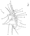
- FIG. 1 is a partial section of an air spring assembly according to the invention shown in a perspective view.
- the air spring assembly comprises an air spring 1 and a bellows 2, which is shown only partially here.
- a rolling piston is not shown here for clarity.
- the bellows 2 is hermetically sealed at its upper, a vehicle frame 3 only partially shown here end with a cover 4.
- the connection between the cover 4 and bellows 2 is formed by a flanging 5 of the lid 4 around a bead 6 of the bellows 2.
- the lid 4 has a bottom 7, wherein the bottom 7 has beads 8, which protrude in the direction of the frame 3 from the lid bottom 7.
- the cover 4 is fastened by means of a screw-nut connection 9 at an angle 10.
- the angle 10 has at its lid 4 associated leg 11 has a contour 12 which corresponds to the beads 8 of the lid base 7 and engages in this.
- the angle 10 has to improve the rigidity still corner struts 13, which, like the contour 12, can be generated by a non-cutting forming process.
- the angle 10 is fastened to the frame 3 by screw-nut connections 14.
Landscapes
- Engineering & Computer Science (AREA)
- Mechanical Engineering (AREA)
- General Engineering & Computer Science (AREA)
- Fluid-Damping Devices (AREA)
Applications Claiming Priority (1)
| Application Number | Priority Date | Filing Date | Title |
|---|---|---|---|
| DE102010016768A DE102010016768A1 (de) | 2010-05-04 | 2010-05-04 | Luftfederanordnung für ein Nutzfahrzeug |
Publications (2)
| Publication Number | Publication Date |
|---|---|
| EP2385269A2 true EP2385269A2 (fr) | 2011-11-09 |
| EP2385269A3 EP2385269A3 (fr) | 2017-09-20 |
Family
ID=44462109
Family Applications (1)
| Application Number | Title | Priority Date | Filing Date |
|---|---|---|---|
| EP11160108.4A Withdrawn EP2385269A3 (fr) | 2010-05-04 | 2011-03-29 | Installation d'un ressort à air pour un véhicule utilitaire |
Country Status (2)
| Country | Link |
|---|---|
| EP (1) | EP2385269A3 (fr) |
| DE (1) | DE102010016768A1 (fr) |
Cited By (5)
| Publication number | Priority date | Publication date | Assignee | Title |
|---|---|---|---|---|
| US20150035212A1 (en) * | 2009-10-14 | 2015-02-05 | Firestone Industrial Products Company, Llc | End member, gas spring assembly and method |
| DK201400530A1 (da) * | 2014-09-18 | 2016-04-04 | Hbn Teknik As | Monteringssystem til montering af affjedringskomponenter på et køretøj |
| US11472247B2 (en) * | 2019-10-01 | 2022-10-18 | Firestone Industrial Products Company, Llc | Mounting bracket assemblies as well as suspension assemblies, kits and methods including same |
| US20230234657A1 (en) * | 2017-09-22 | 2023-07-27 | Link Mfg., Ltd. | Mounting brackets for auxiliary suspension systems |
| US11820188B2 (en) | 2021-07-08 | 2023-11-21 | Link Mfg., Ltd. | Driven lift axles and associated systems and methods |
Citations (1)
| Publication number | Priority date | Publication date | Assignee | Title |
|---|---|---|---|---|
| DE29510199U1 (de) | 1995-06-23 | 1995-08-31 | Trenkamp & Gehle GmbH, 49413 Dinklage | Luftfedervorrichtung für Fahrzeugachsen |
Family Cites Families (3)
| Publication number | Priority date | Publication date | Assignee | Title |
|---|---|---|---|---|
| EP1222409B1 (fr) * | 1999-10-22 | 2004-12-22 | BFS Diversified Products, LLC | Support et plaque de montage d'extremite monobloc pour ressort pneumatique |
| US6398179B1 (en) * | 2000-01-19 | 2002-06-04 | General Motors Corporation | Fastener-less spring assembly |
| DE202008013805U1 (de) * | 2008-12-02 | 2009-02-19 | Continental Aktiengesellschaft | Gasfeder, beispielsweise Luftfeder |
-
2010
- 2010-05-04 DE DE102010016768A patent/DE102010016768A1/de not_active Ceased
-
2011
- 2011-03-29 EP EP11160108.4A patent/EP2385269A3/fr not_active Withdrawn
Patent Citations (1)
| Publication number | Priority date | Publication date | Assignee | Title |
|---|---|---|---|---|
| DE29510199U1 (de) | 1995-06-23 | 1995-08-31 | Trenkamp & Gehle GmbH, 49413 Dinklage | Luftfedervorrichtung für Fahrzeugachsen |
Cited By (9)
| Publication number | Priority date | Publication date | Assignee | Title |
|---|---|---|---|---|
| US20150035212A1 (en) * | 2009-10-14 | 2015-02-05 | Firestone Industrial Products Company, Llc | End member, gas spring assembly and method |
| US9371881B2 (en) * | 2009-10-14 | 2016-06-21 | Firestone Industrial Products Company, Llc | End member, gas spring assembly and method |
| DK201400530A1 (da) * | 2014-09-18 | 2016-04-04 | Hbn Teknik As | Monteringssystem til montering af affjedringskomponenter på et køretøj |
| US20230234657A1 (en) * | 2017-09-22 | 2023-07-27 | Link Mfg., Ltd. | Mounting brackets for auxiliary suspension systems |
| US11904963B2 (en) * | 2017-09-22 | 2024-02-20 | Link Mfg., Ltd. | Mounting brackets for auxiliary suspension systems |
| US11472247B2 (en) * | 2019-10-01 | 2022-10-18 | Firestone Industrial Products Company, Llc | Mounting bracket assemblies as well as suspension assemblies, kits and methods including same |
| US11897299B2 (en) | 2019-10-01 | 2024-02-13 | Firestone Industrial Products Company, Llc | Mounting bracket assemblies as well as suspension assemblies, kits and methods including same |
| US11820188B2 (en) | 2021-07-08 | 2023-11-21 | Link Mfg., Ltd. | Driven lift axles and associated systems and methods |
| US12162321B2 (en) | 2021-07-08 | 2024-12-10 | Link Mfg., Ltd. | Driven lift axles and associated systems and methods |
Also Published As
| Publication number | Publication date |
|---|---|
| EP2385269A3 (fr) | 2017-09-20 |
| DE102010016768A1 (de) | 2011-11-10 |
Similar Documents
| Publication | Publication Date | Title |
|---|---|---|
| DE102010035805A1 (de) | Druckentlastungsventil für eine Fahrzeugkarosserie | |
| DE102008047463A1 (de) | Fahrzeugtür | |
| DE102015109187A1 (de) | Haubenaufbau | |
| DE102012113211A1 (de) | Verstärkungsstruktur für vorderen Fahrzeugaufbau | |
| EP2531383B1 (fr) | Chassis pour un rétracteur de ceinture de sécurité | |
| DE102007053171A1 (de) | Motorhaube für ein Kraftfahrzeug | |
| EP2385269A2 (fr) | Installation d'un ressort à air pour un véhicule utilitaire | |
| DE102014222161A1 (de) | Fahrzeugtür | |
| DE202014104614U1 (de) | Karosserie und Fahrzeug mit einer solchen Karosserie | |
| DE102014211086A1 (de) | Fahrzeugfrontstruktur | |
| DE102017108518A1 (de) | Montageplattenanordnung und ein entsprechendes Verfahren | |
| EP3183467B1 (fr) | Agencement de support de groupe | |
| EP3423336B1 (fr) | Carrosserie de véhicule | |
| DE102014005023A1 (de) | Längslenker sowie Achseinbindung mit einem derartigen Längslenker und Fahrzeug mit einer derartigen Achseinbindung | |
| DE102014214561A1 (de) | Frontendmodul | |
| DE102011110910A1 (de) | Verstärkungsrahmen und Verfahren zum Anbringen eines Verstärkungsrahmens in einer Fahrzeugkarosserie | |
| EP1321319B1 (fr) | Palier supportant la jambe de suspension | |
| DE102008036286A1 (de) | Vorrichtung für eine schwenkbare Lagerung von nebeneinander angeordneten Rückenlehnen | |
| DE10338065A1 (de) | Sicherheitsvorrichtung | |
| DE102006013049B3 (de) | Lageranordnung für die Kolbenstange eines Kolben-Zylinder-Aggregats | |
| DE102017209078A1 (de) | Verfahren zur Herstellung einer Federanordnung eines Fahrzeugs | |
| DE102014116726A1 (de) | Fahrzeug | |
| DE102006030452B4 (de) | Positionierhilfe für die Montage einer Luftfeder an einem Tragblech eines Fahrzeugs | |
| EP2354398B1 (fr) | Appui de charnière pour une porte de véhicule | |
| DE202014100687U1 (de) | Als Wendescharnier ausgebildetes Kraftfahrzeugtürscharnier |
Legal Events
| Date | Code | Title | Description |
|---|---|---|---|
| AK | Designated contracting states |
Kind code of ref document: A2 Designated state(s): AL AT BE BG CH CY CZ DE DK EE ES FI FR GB GR HR HU IE IS IT LI LT LU LV MC MK MT NL NO PL PT RO RS SE SI SK SM TR |
|
| AX | Request for extension of the european patent |
Extension state: BA ME |
|
| PUAI | Public reference made under article 153(3) epc to a published international application that has entered the european phase |
Free format text: ORIGINAL CODE: 0009012 |
|
| PUAL | Search report despatched |
Free format text: ORIGINAL CODE: 0009013 |
|
| AK | Designated contracting states |
Kind code of ref document: A3 Designated state(s): AL AT BE BG CH CY CZ DE DK EE ES FI FR GB GR HR HU IE IS IT LI LT LU LV MC MK MT NL NO PL PT RO RS SE SI SK SM TR |
|
| AX | Request for extension of the european patent |
Extension state: BA ME |
|
| RIC1 | Information provided on ipc code assigned before grant |
Ipc: F16F 9/05 20060101AFI20170816BHEP |
|
| STAA | Information on the status of an ep patent application or granted ep patent |
Free format text: STATUS: THE APPLICATION HAS BEEN WITHDRAWN |
|
| 17P | Request for examination filed |
Effective date: 20180320 |
|
| RBV | Designated contracting states (corrected) |
Designated state(s): AL AT BE BG CH CY CZ DE DK EE ES FI FR GB GR HR HU IE IS IT LI LT LU LV MC MK MT NL NO PL PT RO RS SE SI SK SM TR |
|
| 18W | Application withdrawn |
Effective date: 20180417 |