EP2385296A2 - Lampe murale et/ou plafonnière - Google Patents
Lampe murale et/ou plafonnière Download PDFInfo
- Publication number
- EP2385296A2 EP2385296A2 EP11003700A EP11003700A EP2385296A2 EP 2385296 A2 EP2385296 A2 EP 2385296A2 EP 11003700 A EP11003700 A EP 11003700A EP 11003700 A EP11003700 A EP 11003700A EP 2385296 A2 EP2385296 A2 EP 2385296A2
- Authority
- EP
- European Patent Office
- Prior art keywords
- reflector
- light
- circuit board
- printed circuit
- reflectors
- Prior art date
- Legal status (The legal status is an assumption and is not a legal conclusion. Google has not performed a legal analysis and makes no representation as to the accuracy of the status listed.)
- Withdrawn
Links
- 238000009826 distribution Methods 0.000 claims abstract description 9
- 230000000295 complement effect Effects 0.000 claims abstract description 5
- 230000005855 radiation Effects 0.000 claims abstract description 3
- 238000001816 cooling Methods 0.000 claims description 14
- 238000005286 illumination Methods 0.000 claims description 8
- 238000012546 transfer Methods 0.000 claims description 7
- 239000002184 metal Substances 0.000 claims description 3
- 230000000007 visual effect Effects 0.000 claims description 3
- 241000219739 Lens Species 0.000 description 78
- 238000011161 development Methods 0.000 description 11
- 238000013461 design Methods 0.000 description 6
- 230000004313 glare Effects 0.000 description 6
- 238000002156 mixing Methods 0.000 description 6
- 239000003086 colorant Substances 0.000 description 5
- 230000001154 acute effect Effects 0.000 description 4
- 230000017525 heat dissipation Effects 0.000 description 4
- 239000000463 material Substances 0.000 description 4
- 239000013039 cover film Substances 0.000 description 3
- 230000000694 effects Effects 0.000 description 3
- 239000000203 mixture Substances 0.000 description 3
- 230000001629 suppression Effects 0.000 description 3
- 238000000149 argon plasma sintering Methods 0.000 description 2
- 238000005266 casting Methods 0.000 description 2
- 238000000576 coating method Methods 0.000 description 2
- 239000010408 film Substances 0.000 description 2
- 238000004519 manufacturing process Methods 0.000 description 2
- 230000003287 optical effect Effects 0.000 description 2
- 239000011265 semifinished product Substances 0.000 description 2
- 240000004322 Lens culinaris Species 0.000 description 1
- 230000015572 biosynthetic process Effects 0.000 description 1
- 238000005422 blasting Methods 0.000 description 1
- 239000003795 chemical substances by application Substances 0.000 description 1
- 239000011248 coating agent Substances 0.000 description 1
- 239000011247 coating layer Substances 0.000 description 1
- 239000004020 conductor Substances 0.000 description 1
- 238000009749 continuous casting Methods 0.000 description 1
- 230000007423 decrease Effects 0.000 description 1
- 230000001419 dependent effect Effects 0.000 description 1
- 239000000428 dust Substances 0.000 description 1
- 238000001125 extrusion Methods 0.000 description 1
- 238000005562 fading Methods 0.000 description 1
- 239000011521 glass Substances 0.000 description 1
- 238000003780 insertion Methods 0.000 description 1
- 230000037431 insertion Effects 0.000 description 1
- 238000009434 installation Methods 0.000 description 1
- 230000001678 irradiating effect Effects 0.000 description 1
- 238000000034 method Methods 0.000 description 1
- 239000011505 plaster Substances 0.000 description 1
- 229920001296 polysiloxane Polymers 0.000 description 1
- 238000007493 shaping process Methods 0.000 description 1
- 239000011343 solid material Substances 0.000 description 1
Images



Classifications
-
- F—MECHANICAL ENGINEERING; LIGHTING; HEATING; WEAPONS; BLASTING
- F21—LIGHTING
- F21V—FUNCTIONAL FEATURES OR DETAILS OF LIGHTING DEVICES OR SYSTEMS THEREOF; STRUCTURAL COMBINATIONS OF LIGHTING DEVICES WITH OTHER ARTICLES, NOT OTHERWISE PROVIDED FOR
- F21V5/00—Refractors for light sources
- F21V5/007—Array of lenses or refractors for a cluster of light sources, e.g. for arrangement of multiple light sources in one plane
-
- F—MECHANICAL ENGINEERING; LIGHTING; HEATING; WEAPONS; BLASTING
- F21—LIGHTING
- F21S—NON-PORTABLE LIGHTING DEVICES; SYSTEMS THEREOF; VEHICLE LIGHTING DEVICES SPECIALLY ADAPTED FOR VEHICLE EXTERIORS
- F21S4/00—Lighting devices or systems using a string or strip of light sources
- F21S4/20—Lighting devices or systems using a string or strip of light sources with light sources held by or within elongate supports
-
- F—MECHANICAL ENGINEERING; LIGHTING; HEATING; WEAPONS; BLASTING
- F21—LIGHTING
- F21S—NON-PORTABLE LIGHTING DEVICES; SYSTEMS THEREOF; VEHICLE LIGHTING DEVICES SPECIALLY ADAPTED FOR VEHICLE EXTERIORS
- F21S8/00—Lighting devices intended for fixed installation
- F21S8/02—Lighting devices intended for fixed installation of recess-mounted type, e.g. downlighters
-
- F—MECHANICAL ENGINEERING; LIGHTING; HEATING; WEAPONS; BLASTING
- F21—LIGHTING
- F21S—NON-PORTABLE LIGHTING DEVICES; SYSTEMS THEREOF; VEHICLE LIGHTING DEVICES SPECIALLY ADAPTED FOR VEHICLE EXTERIORS
- F21S8/00—Lighting devices intended for fixed installation
- F21S8/03—Lighting devices intended for fixed installation of surface-mounted type
- F21S8/033—Lighting devices intended for fixed installation of surface-mounted type the surface being a wall or like vertical structure, e.g. building facade
-
- F—MECHANICAL ENGINEERING; LIGHTING; HEATING; WEAPONS; BLASTING
- F21—LIGHTING
- F21V—FUNCTIONAL FEATURES OR DETAILS OF LIGHTING DEVICES OR SYSTEMS THEREOF; STRUCTURAL COMBINATIONS OF LIGHTING DEVICES WITH OTHER ARTICLES, NOT OTHERWISE PROVIDED FOR
- F21V13/00—Producing particular characteristics or distribution of the light emitted by means of a combination of elements specified in two or more of main groups F21V1/00 - F21V11/00
- F21V13/02—Combinations of only two kinds of elements
- F21V13/04—Combinations of only two kinds of elements the elements being reflectors and refractors
-
- F—MECHANICAL ENGINEERING; LIGHTING; HEATING; WEAPONS; BLASTING
- F21—LIGHTING
- F21V—FUNCTIONAL FEATURES OR DETAILS OF LIGHTING DEVICES OR SYSTEMS THEREOF; STRUCTURAL COMBINATIONS OF LIGHTING DEVICES WITH OTHER ARTICLES, NOT OTHERWISE PROVIDED FOR
- F21V29/00—Protecting lighting devices from thermal damage; Cooling or heating arrangements specially adapted for lighting devices or systems
-
- F—MECHANICAL ENGINEERING; LIGHTING; HEATING; WEAPONS; BLASTING
- F21—LIGHTING
- F21V—FUNCTIONAL FEATURES OR DETAILS OF LIGHTING DEVICES OR SYSTEMS THEREOF; STRUCTURAL COMBINATIONS OF LIGHTING DEVICES WITH OTHER ARTICLES, NOT OTHERWISE PROVIDED FOR
- F21V29/00—Protecting lighting devices from thermal damage; Cooling or heating arrangements specially adapted for lighting devices or systems
- F21V29/50—Cooling arrangements
- F21V29/70—Cooling arrangements characterised by passive heat-dissipating elements, e.g. heat-sinks
-
- F—MECHANICAL ENGINEERING; LIGHTING; HEATING; WEAPONS; BLASTING
- F21—LIGHTING
- F21V—FUNCTIONAL FEATURES OR DETAILS OF LIGHTING DEVICES OR SYSTEMS THEREOF; STRUCTURAL COMBINATIONS OF LIGHTING DEVICES WITH OTHER ARTICLES, NOT OTHERWISE PROVIDED FOR
- F21V29/00—Protecting lighting devices from thermal damage; Cooling or heating arrangements specially adapted for lighting devices or systems
- F21V29/50—Cooling arrangements
- F21V29/70—Cooling arrangements characterised by passive heat-dissipating elements, e.g. heat-sinks
- F21V29/74—Cooling arrangements characterised by passive heat-dissipating elements, e.g. heat-sinks with fins or blades
- F21V29/76—Cooling arrangements characterised by passive heat-dissipating elements, e.g. heat-sinks with fins or blades with essentially identical parallel planar fins or blades, e.g. with comb-like cross-section
-
- F—MECHANICAL ENGINEERING; LIGHTING; HEATING; WEAPONS; BLASTING
- F21—LIGHTING
- F21V—FUNCTIONAL FEATURES OR DETAILS OF LIGHTING DEVICES OR SYSTEMS THEREOF; STRUCTURAL COMBINATIONS OF LIGHTING DEVICES WITH OTHER ARTICLES, NOT OTHERWISE PROVIDED FOR
- F21V7/00—Reflectors for light sources
- F21V7/0083—Array of reflectors for a cluster of light sources, e.g. arrangement of multiple light sources in one plane
-
- F—MECHANICAL ENGINEERING; LIGHTING; HEATING; WEAPONS; BLASTING
- F21—LIGHTING
- F21V—FUNCTIONAL FEATURES OR DETAILS OF LIGHTING DEVICES OR SYSTEMS THEREOF; STRUCTURAL COMBINATIONS OF LIGHTING DEVICES WITH OTHER ARTICLES, NOT OTHERWISE PROVIDED FOR
- F21V7/00—Reflectors for light sources
- F21V7/0008—Reflectors for light sources providing for indirect lighting
-
- F—MECHANICAL ENGINEERING; LIGHTING; HEATING; WEAPONS; BLASTING
- F21—LIGHTING
- F21V—FUNCTIONAL FEATURES OR DETAILS OF LIGHTING DEVICES OR SYSTEMS THEREOF; STRUCTURAL COMBINATIONS OF LIGHTING DEVICES WITH OTHER ARTICLES, NOT OTHERWISE PROVIDED FOR
- F21V7/00—Reflectors for light sources
- F21V7/0025—Combination of two or more reflectors for a single light source
-
- F—MECHANICAL ENGINEERING; LIGHTING; HEATING; WEAPONS; BLASTING
- F21—LIGHTING
- F21Y—INDEXING SCHEME ASSOCIATED WITH SUBCLASSES F21K, F21L, F21S and F21V, RELATING TO THE FORM OR THE KIND OF THE LIGHT SOURCES OR OF THE COLOUR OF THE LIGHT EMITTED
- F21Y2103/00—Elongate light sources, e.g. fluorescent tubes
- F21Y2103/10—Elongate light sources, e.g. fluorescent tubes comprising a linear array of point-like light-generating elements
-
- F—MECHANICAL ENGINEERING; LIGHTING; HEATING; WEAPONS; BLASTING
- F21—LIGHTING
- F21Y—INDEXING SCHEME ASSOCIATED WITH SUBCLASSES F21K, F21L, F21S and F21V, RELATING TO THE FORM OR THE KIND OF THE LIGHT SOURCES OR OF THE COLOUR OF THE LIGHT EMITTED
- F21Y2115/00—Light-generating elements of semiconductor light sources
- F21Y2115/10—Light-emitting diodes [LED]
Definitions
- the present invention generally relates to a lamp and in particular a wall and / or ceiling lamp in the form of a wallwashers, with a plurality of bulbs, preferably in the form of LEDs, which sit on a printed circuit board, which is provided for the power supply and / or control of the lighting means , And a reflector assembly for deflecting the light emitted by the light source in the space to be illuminated.
- the present invention seeks to provide an improved luminaire, which avoids the disadvantages of the prior art and the latter develops in an advantageous manner.
- a small-sized, simple and inexpensive to produce wall and / or ceiling light is to be created, which can produce a high amount of light with a high luminaire efficiency of operation at a designated target area with uniform light distribution, without buying this with a dazzling effect.
- the invention proposes between the reflector assembly and To provide the plurality of bulbs lenses, each associated with one or a subset of the bulbs and capture the light emitted therefrom substantially completely and throw on the reflector assembly.
- the lamps are each assigned a lens which essentially completely captures the light emitted by the luminous means and at least partially throws it onto the reflector arrangement.
- a plurality of lenses are provided for a plurality of the lighting means, wherein in particular also all lamps can be associated with such lenses.
- the lenses can be aligned parallel to one another and arranged next to one another in accordance with the arrangement grid of the lighting means, in particular in a row.
- the plurality of lenses can be connected together to form a common, line-shaped lens component, which can be mounted separately as such.
- a common, line-shaped lens component which can be mounted separately as such.
- the lenses can be molded integrally as part of a lens line, in particular molded from plastic, wherein optionally in a multi-component process, the lenses themselves can be cast from a different material than the provided between the lenses connecting webs or the support profile on which the several lenses are formed.
- the lenses are shaped such that they have complementary and / or overlapping radiation areas such that the light emitted by the reflector arrangement in the space to be illuminated has a uniform light intensity distribution, in particular such that the irradiated wall or floor surface uniformly bright is lit.
- the light cones emitted by the lenses can already complement or overlap one another on the reflector they are irradiating and mix with it.
- the lenses may also be shaped such that the lenses, in cooperation with the reflector arrangement, result in the desired complementation, overlapping and / or mixing of the light cones, for example such that the light cones cast by the lenses onto the reflector arrangement are still distinguishable on the reflector arrangement and complement or mix only after blasting from the reflector assembly in the desired manner, so that the irradiated wall surface is uniformly illuminated and there a uniform light intensity distribution is achieved.
- the said lenses can in this case basically be formed differently, wherein advantageously free-form lenses and / or lenses with an asymmetrical emission characteristic can be provided in order to cast the light emitted by a respective point-shaped luminous means in the desired distribution onto the reflector, the design of which can thereby be simplified ,
- the lenses are advantageously designed and arranged so that they completely capture and redirect light emitted by the point light source.
- the respective lens may have on its side associated with the lamp a cup-shaped entrance contour, with which the lens is placed over the point-shaped light source, so that obliquely or laterally emitted light enters the lens.
- LEDs can be provided as lighting means.
- the punctiform light source in particular LED
- the punctiform light source in particular LED
- the said coupling-out lens can in this case basically be designed differently and form a per se known LED package together with the emitter and the drive chip of the LED.
- the coupling-out lens may, for example, form a dome-shaped cover in the form of a lens, or else be in the form of a silicone lens made of solid material.
- said coupling-out lens does not necessarily have to be dome-shaped or dome-shaped, but may also have other contours, for example in the form of an approximately plate-shaped casting, which covers the emitter and chip of the LED. If the punctiform light source is provided with such a coupling-out lens, the abovementioned lenses are set via this coupling-out lens or arranged downstream of it in order to cast the light onto the common reflector in the desired manner.
- the aforementioned reflector arrangement can basically be designed differently.
- the reflector arrangement comprises at least a first reflector, which deflects the light coming from the lenses forth and radiates in the desired manner in the space to be illuminated.
- said first reflector may extend along the printed circuit board across the plurality of bulbs and / or lenses so that the plurality of bulbs or the plurality of lenses cast light onto the common first reflector.
- the reflector arrangement may also comprise at least one second reflector which is arranged between the illuminant and the first reflector such that light emitted by the illuminant and / or emitted by the associated lens is first deflected by the second reflector and thrown onto the first reflector, which then redirects the light and throws it into the room to be illuminated.
- a plurality of such second reflectors can be provided, which are each assigned separately to a single luminous means, possibly also a subgroup of the luminous means.
- each of the bulbs and / or lenses can be provided to assign reflector pots, which are the illuminants and / or lenses individually enclosing arranged on the circuit board and throw the light emitted by the bulbs light on the common, another reflector, the is provided for several lamps simultaneously.
- reflector pots which are the illuminants and / or lenses individually enclosing arranged on the circuit board and throw the light emitted by the bulbs light on the common, another reflector, the is provided for several lamps simultaneously.
- the cup-shaped individual reflectors cover the illuminants in particular also against viewing directions which lie in a vertical plane below the luminaire or are only slightly inclined relative to this vertical plane, ie in other words an observer standing essentially underneath the luminaire then not blinded when he sees substantially along the longitudinal direction of the printed circuit board in the lamp, even not if the angle is very shallow, for example, because the lamp or the lamp section is looked at the other end of the room.
- the at least one lens can be used in combination with the aforementioned second reflectors.
- at least one of the second reflectors can be replaced by at least one lens, in particular if the corresponding lens is designed so that it casts the light emitted by the illuminant completely onto the first reflector.
- a respective lens may also be replaced by a second reflector.
- the plurality of lighting means can in principle be provided in various arrangements on the printed circuit board, for example a staggered, matrix-shaped arrangement of the lighting means.
- a particularly advantageous embodiment of the invention can be that the bulbs are spaced from each other in a row next to each other. This makes it possible in particular to form a small-wall and / or ceiling lamp with approximately slit-shaped light exit. It may be advantageous if the circuit board has an elongated, generally slim contour, for example in the form of a rectangle.
- the light sources associated with a common printed circuit board can in principle be designed differently.
- the different design of the lighting means may consist of different light colors, different powers and / or different illuminant geometries, preferably punctiform, but also linear bulbs can be used.
- LEDs light-emitting diodes
- a plurality of identically designed lighting means may be arranged on a common printed circuit board.
- the at least one light source is arranged dimmed.
- the bulbs are concealed by Korpuskonturen so that a direct, straight line of sight is prevented in the bulbs when mounting the light on the ceiling.
- the second, cup-shaped reflectors enclose the closed ring-shaped lamps directly adjacent to the surface of the printed circuit board.
- the pot reflectors enclosing the lamps almost completely capture the light emitted by the lamp and throw it in the desired direction with a desired beam path in the predetermined target area or on the common further reflector.
- the reflector arrangement essentially adjoins directly the printed circuit board front side carrying the at least one luminous means, so that light emitted by the luminous means substantially parallel to the printed circuit board is captured by the reflector.
- the lamp is as it were enclosed by the reflector assembly and the circuit board.
- the first reflector viewed from the space to be illuminated, is arranged behind the lighting means, while the cup-shaped second reflectors Seen from the illuminated space before the at least one light source are arranged.
- the rear, first reflector viewed from the room to be illuminated, may have different shapes with respect to its shape.
- the first reflector may have a groove-shaped, concave curvature, wherein advantageously the radius of curvature may increase with increasing distance from the printed circuit board and / or the lighting means.
- Said first reflector extends along the printed circuit board over the plurality of light sources and also over the corresponding plurality of second reflectors, so that the plurality of second reflectors cast light onto the common first reflector.
- the reflector arrangement and / or the lenses are advantageously shaped such that the light cone emitted by at least two adjacent bulbs via associated lenses and / or second reflectors overlap one another and at least after deflection by the first reflector on the wall to be illuminated the light of at least two different bulbs mixed.
- said second reflectors may be designed such that three or more light cones of adjacent bulbs after the reflector arrangement overlap on the wall to be illuminated.
- the second reflectors can basically be designed differently.
- the second reflectors can be contoured in the shape of a circular-frustum, wherein the cone-opening angle can be adapted to the spacing of the lighting means from each other.
- the cup-shaped second reflectors a Cone opening angle of 2 x 20 ° to 2 x 40 ° and preferably about 2 x 30 ° have.
- the depth of the cup-shaped second reflectors and / or their diameter can in this case be dimensioned such that the second reflectors each have a Ausblendwinkel of 2 x 45 ° to 2 x 65 ° and in particular about 2 x 55 °.
- the reflector arrangement is such that the lighting means are arranged on the front side of the printed circuit board, which faces the space to be illuminated or the wall to be illuminated.
- the lighting means are arranged on the front side of the printed circuit board, which faces the space to be illuminated or the wall to be illuminated.
- the cup-shaped second reflectors are designed and / or arranged the second reflectors supporting printed circuit board arranged in particular tilted, that the second reflectors release a visual axis directly into the light source only in one area, in which a common observer of usual size can not get away with his eyes.
- the second reflectors cover all visual axes directly to those in the second Reflectors arranged light sources, which would be tilted down to a horizontal ceiling plane by more than 66 °, in particular more than 45 ° downwards, that would be directed steeper than 66 ° or 45 ° upwards to the ceiling.
- the luminaire has a ceiling mounting plane that extends parallel to the ceiling when mounted on the ceiling. Based on this ceiling mounting plane, the second reflectors cover all sight axes that would be inclined more than 45 ° in relation to the ceiling mounting plane. In a mounting of the lamp at a standard ceiling height of about 2.50 m to 3.00 m at a distance of about 0.5 m - 1 m in front of the illuminated wall this results in a complete glare, as a person, even if they is directly on the wall to be illuminated, can not look directly into the bulbs.
- a transparent cover may be provided in front of the cup-shaped, second reflectors, which may at least partially close said second reflectors.
- a common cover may be provided, which extends over the plurality of second reflectors away.
- a plurality of such covers can be provided, which are each associated with a single reflector or a subset of second reflectors.
- the said cover can basically consist of different materials, for example be shaped in the form of a glass or plastic panel.
- the cover used is a transparent covering film, which is blinded in front of the second reflectors, for example, can be placed flush on its outer edge in order to close the reflectors.
- the said cover can serve here not only as a dust cover, but above all form an optical means for influencing the light emission.
- a cover film can be used with a surface structuring and / or light-scattering agents, whereby, for example, a improved mixing of the light emitted by the plurality of LEDs and thrown onto the first reflector light can be achieved, wherein such a cover can also be arranged in front of the lenses.
- the reflector arrangement advantageously throws a light wedge on the wall to be illuminated as evenly as possible, which may have a wedge angle of 10 ° to about 90 °, wherein advantageously an upper side of said light wedge is bounded by a horizontal plane or optionally a horizontal plane slightly inclined at an acute angle.
- the printed circuit board is tilted at an acute angle relative to the aforementioned ceiling mounting plane of the lamp, wherein the tilt angle of the printed circuit board with respect to said ceiling mounting plane is less than 90 °.
- the printed circuit board can be tilted relative to the ceiling mounting plane at an angle of about 70 ° to 90 ° and preferably about 80 °.
- the heat that passes directly from the light source in the circuit board can be the heat that passes directly from the light source in the circuit board, but on the other hand may include the heat, which acts in the form of light rays, for example by scattering and / or reflection on the printed circuit board surface.
- At least one heat sink can be provided, which is associated with the printed circuit board and / or the at least one reflector of the reflector assembly and advantageously by air flows around or flows through and causes the necessary heat dissipation.
- the said heat sink with the Rear side of the printed circuit board and / or the back of the at least one reflector to be connected, so that a heat transfer from the printed circuit board and / or the reflector can be made on the heat sink and discharged from the cooling fins.
- the printed circuit board and the heat sink or the at least one reflector and the heat sink are adapted to one another in an advantageous development of the invention, advantageously such that a full-surface concerns of the heat sink on the printed circuit board back and / or on the reflector backs is provided.
- the heat sink may have corresponding connection surfaces which are adapted to the back side of the printed circuit board and / or the rear side of the reflector.
- the at least one heat sink is designed in such a way that essentially the entire rear side of the printed circuit board and the entire rear side of the first reflector are covered by the heat sink.
- the heat sink and the reflector can in this case be formed as separate components and be adapted to one another in the aforementioned ways. Alternatively, however, it can also be provided that the reflector in the form of a coating is applied directly to the heat sink, so that, so to speak, the corresponding heat sink surface itself operates as a reflector.
- Said printed circuit board can be attached to the heat sink in principle in various ways.
- the printed circuit board is advantageously pressed non-positively against the corresponding heat sink surface and / or connected to this form-fitting manner.
- a preferred embodiment may be that the printed circuit board is seated in a cooling bag in which said printed circuit board is surrounded by opposite sides of the heat sink from its rear side, wherein advantageously said cooling pocket is formed so deep in the heat sink that the printed circuit board with at least one third of its width in said cooling bag sitting, which is in contact with both the front of the circuit board on which the bulbs sit, as well as with the back of the circuit board. Due to the large insertion depth a particularly efficient heat transfer can be achieved, which conducts the heat from the printed circuit board into the heat sink.
- the lamp can basically have different designs.
- the lamp body including at least the common reflector is formed as an endless extruded profile, so that it to a desired length can be cut to length.
- the printed circuit board and the at least one heat sink can each be designed as an endless extruded profile, so that these components of the lamp can be cut to the respective desired lamp length.
- the heat sink has web-shaped cooling ribs which extend parallel to the longitudinal direction of the extruded profile. As a result, very finely formed ribs can be provided, in particular when producing medium extruded profile extrusion or continuous casting, which provide a large heat transfer surface even with a very small overall size of the entire lamp.
- wall and / or ceiling lamp 1 has a total elongated - roughly speaking - bar-shaped contour, so that they can be advantageously integrated into slot-shaped recesses in ceiling and / or wall panels, for example, installed countersunk into corresponding panel slots can.
- this installation option due to the small size of the lamp 1 shows its advantages particularly clearly, can in alternative Use the lamp but also in a projecting arrangement, so to speak, be fixed to plaster and / or freestanding to appropriate fasteners and brackets.
- the mounting on a ceiling at a distance of about 0.5-1 m, preferably about 0.75 m away from the room wall to be illuminated 20; however, the lamp may also be mounted upright on an adjacent wall to illuminate said room wall 20 from the side.
- the lamp 1 comprises a plurality of light sources 2 in the form of button-shaped LEDs 3, which are mounted directly on a printed circuit board 4 and connected to conductors which are integrated in the interior of the printed circuit board 4.
- the LEDs 3 can advantageously be spaced apart from each other side by side, with a slot lamp in the Fig. 6 shown alignment along a straight line can be particularly advantageous.
- differently colored LEDs 3 in red, green and blue are provided, whose light can advantageously homogeneously mix in the target area, so that a simple adjustment of homogeneous light colors is achieved, which is achieved by a good color overlay in the target area.
- the printed circuit board 4 has in the illustrated embodiment an elongated, approximately rectangular contour, wherein it is advantageously formed flat.
- the printed circuit board 4 can be made as a semi-finished product, so to speak, which is then cut to the required length depending on the desired lamp size.
- the arrangement of the LEDs 3 directly on the printed circuit board 4 can be a particularly compact design of the lamp 1 realize and bring about a good heat dissipation.
- the length of the lamp is advantageously almost freely selectable, since the formed as continuous extruded profiles components can be cut to the desired length and along the circuit board 4 a corresponding arbitrary plurality of bulbs 2 can be arranged.
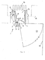
- Fig. 1 shows, the printed circuit board 4 and the LEDs 3 arranged thereon is associated with a reflector assembly 5, which is adjacent to the printed circuit board 4 and the LEDs 3, so to speak encloses together with the printed circuit board front side.
- the in the drawing plane of the Fig. 1 shown LED 3 associated with a lens 23, which captures the light emitted by the LED 3 and completely on the all LEDs 3 common reflector 9 and / or directly into the light wedge 24 or to the lighting room, in particular on the wall 20 to be illuminated throws ,
- the lens 23 may have a pot-shaped contoured entrance side 23a that is slipped over the LED 3 to also capture laterally exiting light.
- said lens 23 may be shaped such that an asymmetrical light intensity distribution is achieved, in particular such that no or only slightly lateral light components are emitted, which would propagate approximately parallel to or only slightly inclined to the straight line connecting the multiple LEDs. In other words, at least partially prevented from the LED 3 light perpendicular to the plane of the Fig. 4 or is radiated to this perpendicular inclined only at an acute angle.
- the aforementioned lenses 23 may be in an advantageous development of the invention part of a common, separately manufactured and assembled component in the form of a Linsenzeile, like this Fig. 2 shows.
- the lenses 23 may be attached to a common plate-shaped or strip-shaped carrier 123 in the embodiment shown, which can be manufactured in the form of semi-finished products of great length and can be cut to the correct length depending on the length of the lamp.
- the lenses may be cast on said support 123 or integrally integrally formed in other ways, in principle, the support 123 and the lenses 23 may be made of the same material. Alternatively, the lenses 23 and the carrier 123 may also be made of different materials, for example manufactured in a multi-component casting process.
- separately manufactured lenses 23 may be subsequently inserted into a prefabricated carrier 123 having corresponding lens receiving recesses.
- the aforementioned reflector arrangement 5, which directly adjoins the printed circuit board 4, defines with reflector surface edges 6 and 7 a light exit cross section 8 which lies in a plane which essentially - roughly speaking - extends perpendicularly to the plane of the printed circuit board 4, cf. Fig. 5 ,
- the reflector arrangement 5 comprises a first reflector 9 which is common to all LEDs and which is irradiated by the light emerging from the lenses 23.
- the lenses 23 thus direct their light cones - which need not have exactly conical form in the mathematical sense - on the common first reflector 9, which then throws the aforementioned light cone in the space to be illuminated.
- the reflector assembly 5 consists solely of said first reflector.
- the reflector arrangement may also comprise at least one further reflector, wherein such a second reflector may be provided in combination with said lenses 23.
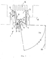
- a further reflector shows the execution Fig. 5 , where for the sake of simplicity and clarity sake, the lenses 23 are omitted, but this may also represent an embodiment of the invention.
- the abovementioned common first reflector 9 and a multiplicity of further reflectors 10 can be provided which are individually assigned to an LED and / or a lens 23, wherein the first reflector 9 is arranged behind the light-emitting diodes 3, viewed from the room to be illuminated the second reflectors 10 viewed from the direction mentioned are arranged in front of and behind the light-emitting diodes 3 and enclose and cover them in the shape of a cup, so that no direct light can be thrown into a glare-relevant spatial area by the light-emitting diodes 3.
- the said second reflectors 10 are, as Fig. 5 shows, arranged directly on the LEDs 3.
- the second reflectors 10 are each cup-shaped in the form of a frusto-conical annular surface and sit together with the enclosed LEDs on the printed circuit board 4, so that the LEDs are peripherally completely enclosed by said second reflectors 10. This extremely small distance or the immediately adjacent arrangement of the second reflectors 10 causes a complete capture even laterally parallel to the printed circuit board radiated light and thus a high efficiency.
- the radius of curvature of the first reflector 9 decreases with increasing distance from the printed circuit board 4.
- Surface area, the two reflectors 9 and 10 are also formed differently.
- the first reflector 9 extends arcuately about - roughly speaking - from the light-emitting diodes 3 facing away, the upper edge of the wide reflectors 10 to about down to the height of the LEDs 3, see. Fig. 5 ,
- the second reflectors 10 form in the illustrated embodiment frusto-conical pots with a cone opening angle of about 2 x 30n.
- the depth of the reflector pots on the order of magnitude is chosen approximately in the region of the larger diameter, wherein advantageously the outer, maximum diameter of the second reflectors about 50% - 400% and in particular about 200% of the depth of the cup-shaped second reflectors, as in FIG. 6 is shown.
- the second reflectors 10 are advantageously designed such that they have a Ausblendwinkel of about 2 x 55 ° in the illustrated embodiment.
- drawn spacing of the lamps which may be on the order of about 10-40 mm and preferably about 25 mm, results in a cross-fading emitted by the individual light beam beams, ie the outgoing of the individual light cone falling on overlapping areas on the first reflector 9, so that a good, uniform mixing of the different light colors of adjacent bulbs is achieved.
- the printed circuit board 4 is tilted at an acute angle to the ceiling-parallel ceiling mounting plane 19, wherein in the illustrated embodiment, the tilt angle 18 is about 80 °.
- the reflector assembly 5 is formed in total such that the lamp emits a light wedge with a wedge angle of 10 ° to 90 °, which illuminates the perpendicular to the ceiling mounting plane 19 extending wall 20 evenly.
- Said light wedge 24 is bounded on its upper side by an approximately ceiling-parallel plane, cf. FIG. 5 ,
- a heat sink 13 is provided, which surrounds the reflectors 9 and 10 of the reflector assembly 5 and the printed circuit board 4 each back.
- the heat sink 13 in this case comprises a plurality of cooling fins 16.
- a cooling body part 14 is provided, which essentially cools the printed circuit board 4 and the first reflector 9.
- the printed circuit board 4 sits in the illustrated embodiment in a slot-shaped cooling pocket 17, which is bounded by the heat sink part 14, said cooling pocket 17 is adapted to the contour of the printed circuit board 4 ,
- said printed circuit board 4 is seated approximately 1 ⁇ 3 to 1 ⁇ 2 of its width in a slot-shaped pocket in the heat sink portion 14, opposite sides of the heat sink part 14 are positively embraced, so that the printed circuit board 4 full and rich against the terminal contour of the aforementioned heat sink part 14th is applied.
- the connecting surfaces of the heat sink 13 to the printed circuit board 4 and to the reflectors 9 and 10 are each conformed to form, it can be advantageously provided that the reflector can be applied directly in the form of a coating layer on the surface of said heat sink.
- the reflector 9 may be formed directly by corresponding surfaces of the heat sink or of coatings applied thereto.
- Fig. 5 shows, advantageously not only the printed circuit board 4, but also the other essential components of the lamp 1 can be formed in the form of endless extruded profiles, so in particular the heat sink member 14 and the reflector 9, so that in a simple manner with small component diversity different lamp sizes can be made.
- the corresponding endless extruded parts only need to be cut to the desired length.
- the individual reflectors 10 are set on the circuit board 4, the individual reflectors 10 are set.
- the outlet cross-section of the second reflectors 10 may be covered with a cover 21, which is formed in the illustrated embodiment of a transparent cover 22.
- Said cover film 22 may in this case have an extension over a plurality of reflectors 10, so that a plurality of reflectors 10 are covered by a common cover 21.
- the covering film 21 can also cover only individual reflector pots 10, so that each reflector pots 10 is assigned a cover 21 individually.
- the cover 21 can sit directly on the edges of the reflector pots 10 and close this.
- Said cover film 21 may be designed differently, for example light-scattering, in order to achieve better mixing of the light emitted by the different LEDs.
Landscapes
- Engineering & Computer Science (AREA)
- General Engineering & Computer Science (AREA)
- Architecture (AREA)
- Non-Portable Lighting Devices Or Systems Thereof (AREA)
- Arrangement Of Elements, Cooling, Sealing, Or The Like Of Lighting Devices (AREA)
Applications Claiming Priority (1)
| Application Number | Priority Date | Filing Date | Title |
|---|---|---|---|
| DE102010019436A DE102010019436A1 (de) | 2010-05-05 | 2010-05-05 | Wand- und/oder Deckenleuchte |
Publications (2)
| Publication Number | Publication Date |
|---|---|
| EP2385296A2 true EP2385296A2 (fr) | 2011-11-09 |
| EP2385296A3 EP2385296A3 (fr) | 2013-10-16 |
Family
ID=44117114
Family Applications (1)
| Application Number | Title | Priority Date | Filing Date |
|---|---|---|---|
| EP11003700.9A Withdrawn EP2385296A3 (fr) | 2010-05-05 | 2011-05-05 | Lampe murale et/ou plafonnière |
Country Status (2)
| Country | Link |
|---|---|
| EP (1) | EP2385296A3 (fr) |
| DE (1) | DE102010019436A1 (fr) |
Cited By (5)
| Publication number | Priority date | Publication date | Assignee | Title |
|---|---|---|---|---|
| JP2013196790A (ja) * | 2012-03-15 | 2013-09-30 | Sharp Corp | 照明装置 |
| WO2013160244A1 (fr) * | 2012-04-24 | 2013-10-31 | Osram Gmbh | Lentille et dispositif d'éclairage associé à la lentille |
| CN104728669A (zh) * | 2013-12-19 | 2015-06-24 | 艾科有限公司 | 灯 |
| EP3165817A1 (fr) * | 2015-11-04 | 2017-05-10 | Zumtobel Lighting GmbH | Dispositif d'éclairage |
| EP3622217A4 (fr) * | 2017-05-08 | 2020-05-20 | JLC-Tech IP, LLC | Éclairage oblique intégré dans une suspente en t inversé |
Families Citing this family (6)
| Publication number | Priority date | Publication date | Assignee | Title |
|---|---|---|---|---|
| DE102013213870A1 (de) * | 2013-07-16 | 2015-01-22 | Zumtobel Lighting Gmbh | Anordnung zur Lichtabgabe |
| DE102013220550A1 (de) * | 2013-10-11 | 2015-04-16 | Zumtobel Lighting Gmbh | LED-Rasterleuchte |
| DE102015014711A1 (de) | 2015-11-17 | 2017-05-18 | Jochen C. Renz | Akustikmodul mit neuartiger Leuchtfunktion |
| DE102017108113A1 (de) | 2017-04-13 | 2018-10-18 | Rzb Rudolf Zimmermann, Bamberg Gmbh | Mehrfachlinsenanordnung für eine Beleuchtungsvorrichtung |
| DE102024126258B3 (de) * | 2024-09-12 | 2025-11-13 | Erco Gmbh | System von Leuchten zur Ausleuchtung einer Gebäudefläche, umfassend unterschiedliche Leuchten mit baugleichen Gehäusen und baugleichen Bündelungs-Optiken |
| DE102024126257A1 (de) * | 2024-09-12 | 2026-03-12 | Erco Gmbh | Leuchte |
Family Cites Families (14)
| Publication number | Priority date | Publication date | Assignee | Title |
|---|---|---|---|---|
| US2323073A (en) * | 1940-12-30 | 1943-06-29 | Ralph B Netting | Light reflector |
| US5097401A (en) * | 1990-07-09 | 1992-03-17 | Ross Eppler | Indirect lighting modifiers for use with fluorescent fixtures |
| DE19920404A1 (de) * | 1999-05-04 | 2000-11-09 | Hella Innenleuchten Systeme Gm | Leuchte mit einem oder mehreren Leuchtmitteln |
| AT5495U1 (de) * | 2001-04-09 | 2002-07-25 | Bartenbach Christian | Leuchtenfeld zur beleuchtung von räumen mit einer vielzahl von leds |
| US6607286B2 (en) * | 2001-05-04 | 2003-08-19 | Lumileds Lighting, U.S., Llc | Lens and lens cap with sawtooth portion for light emitting diode |
| US6871983B2 (en) * | 2001-10-25 | 2005-03-29 | Tir Systems Ltd. | Solid state continuous sealed clean room light fixture |
| US6641284B2 (en) * | 2002-02-21 | 2003-11-04 | Whelen Engineering Company, Inc. | LED light assembly |
| US7048412B2 (en) * | 2002-06-10 | 2006-05-23 | Lumileds Lighting U.S., Llc | Axial LED source |
| DE102006016021A1 (de) * | 2006-04-05 | 2007-10-11 | Zumtobel Lighting Gmbh | Reflektorleuchte |
| DE202007013205U1 (de) * | 2007-07-26 | 2008-12-11 | Erco Leuchten Gmbh | Leuchte |
| DE102007059607A1 (de) * | 2007-12-11 | 2009-06-18 | Bartenbach, Christian, Ing. | Wand- und/oder Deckenleuchte |
| DE102008004352A1 (de) * | 2008-01-15 | 2009-07-16 | Dr. Ing. H.C. F. Porsche Aktiengesellschaft | Fahrzeugscheinwerfer |
| DE102008016496A1 (de) * | 2008-03-31 | 2009-10-01 | Zumtobel Lighting Gmbh | Leuchte mit punktförmiger Lichtquelle und asymmetrischer Lichtabstrahlcharakteristik |
| DE202008007267U1 (de) * | 2008-05-30 | 2008-07-31 | Compound Solar Technology Co., Ltd. | LED-Linseaufbau und den Aufbau verwendende LED-Beleuchtungsanlage |
-
2010
- 2010-05-05 DE DE102010019436A patent/DE102010019436A1/de not_active Withdrawn
-
2011
- 2011-05-05 EP EP11003700.9A patent/EP2385296A3/fr not_active Withdrawn
Non-Patent Citations (1)
| Title |
|---|
| None |
Cited By (7)
| Publication number | Priority date | Publication date | Assignee | Title |
|---|---|---|---|---|
| JP2013196790A (ja) * | 2012-03-15 | 2013-09-30 | Sharp Corp | 照明装置 |
| WO2013160244A1 (fr) * | 2012-04-24 | 2013-10-31 | Osram Gmbh | Lentille et dispositif d'éclairage associé à la lentille |
| CN104728669A (zh) * | 2013-12-19 | 2015-06-24 | 艾科有限公司 | 灯 |
| CN104728669B (zh) * | 2013-12-19 | 2018-03-27 | 艾科有限公司 | 灯 |
| EP3165817A1 (fr) * | 2015-11-04 | 2017-05-10 | Zumtobel Lighting GmbH | Dispositif d'éclairage |
| AT16320U1 (de) * | 2015-11-04 | 2019-07-15 | Zumtobel Lighting Gmbh | Leuchtvorrichtung |
| EP3622217A4 (fr) * | 2017-05-08 | 2020-05-20 | JLC-Tech IP, LLC | Éclairage oblique intégré dans une suspente en t inversé |
Also Published As
| Publication number | Publication date |
|---|---|
| DE102010019436A1 (de) | 2011-11-10 |
| EP2385296A3 (fr) | 2013-10-16 |
Similar Documents
| Publication | Publication Date | Title |
|---|---|---|
| DE102010019436A1 (de) | Wand- und/oder Deckenleuchte | |
| EP1043542B2 (fr) | Système d' éclairage pour installation au plafond ou au mur d' une pièce | |
| EP1154200B1 (fr) | Distributeur de lumière pour un système d'éclairage, système d'éclairage et utilisation d' un système d'éclairage | |
| EP1956289B1 (fr) | Luminaire | |
| EP2071227A1 (fr) | Luminaire pour mur et/ou plafond | |
| EP2492585A2 (fr) | Elément d'éclairage, notamment pour un éclairage au sol | |
| DE102011078287A1 (de) | Lichtlenkungselement | |
| DE102011012130A1 (de) | Beleuchtungsvorrichtung | |
| EP2563189A1 (fr) | Tablette de rayonnage en verre, éclairée par la tranche | |
| DE102010062454A1 (de) | Anordnung zur Lichtabgabe | |
| WO2018108745A1 (fr) | Dispositif d'éclairage | |
| EP0716262A1 (fr) | Armature d'éclairage pour sources lumineuses linéaires | |
| EP2418420A2 (fr) | Dispositif d'éclairage | |
| EP2492578A2 (fr) | Système d'éclairage | |
| EP2988062B1 (fr) | Luminaire | |
| DE19923224A1 (de) | Beleuchtungsanordnung zur Anbringung an der Decke oder einer Wand eines Raumes | |
| EP4509755A1 (fr) | Dispositif d'éclairage | |
| DE102017108113A1 (de) | Mehrfachlinsenanordnung für eine Beleuchtungsvorrichtung | |
| EP3865761B1 (fr) | Luminaire à fonction combinée de luminaire insert et de spot | |
| EP2872936A1 (fr) | Injection latérale de lumière | |
| DE10354176A1 (de) | Signalleuchte | |
| DE102010000195B4 (de) | Beleuchtungskörper mit einer Lichtquelle und einem optischen Diffusor | |
| EP3919808B1 (fr) | Luminaire | |
| EP2058582A1 (fr) | Lampe à DEL | |
| EP3034928B1 (fr) | Éclairage et moyen d'eclairage associe |
Legal Events
| Date | Code | Title | Description |
|---|---|---|---|
| AK | Designated contracting states |
Kind code of ref document: A2 Designated state(s): AL AT BE BG CH CY CZ DE DK EE ES FI FR GB GR HR HU IE IS IT LI LT LU LV MC MK MT NL NO PL PT RO RS SE SI SK SM TR |
|
| AX | Request for extension of the european patent |
Extension state: BA ME |
|
| PUAI | Public reference made under article 153(3) epc to a published international application that has entered the european phase |
Free format text: ORIGINAL CODE: 0009012 |
|
| RIN1 | Information on inventor provided before grant (corrected) |
Inventor name: BARTENBACH, CHRISTIAN |
|
| PUAL | Search report despatched |
Free format text: ORIGINAL CODE: 0009013 |
|
| AK | Designated contracting states |
Kind code of ref document: A3 Designated state(s): AL AT BE BG CH CY CZ DE DK EE ES FI FR GB GR HR HU IE IS IT LI LT LU LV MC MK MT NL NO PL PT RO RS SE SI SK SM TR |
|
| AX | Request for extension of the european patent |
Extension state: BA ME |
|
| RIC1 | Information provided on ipc code assigned before grant |
Ipc: F21V 29/00 20060101ALI20130909BHEP Ipc: F21Y 103/00 20060101ALI20130909BHEP Ipc: F21V 5/00 20060101ALI20130909BHEP Ipc: F21S 8/00 20060101AFI20130909BHEP Ipc: F21S 4/00 20060101ALI20130909BHEP Ipc: F21S 8/02 20060101ALI20130909BHEP Ipc: F21V 7/00 20060101ALI20130909BHEP Ipc: F21V 13/04 20060101ALI20130909BHEP Ipc: F21Y 101/02 20060101ALN20130909BHEP |
|
| 17P | Request for examination filed |
Effective date: 20131016 |
|
| STAA | Information on the status of an ep patent application or granted ep patent |
Free format text: STATUS: THE APPLICATION IS DEEMED TO BE WITHDRAWN |
|
| 18D | Application deemed to be withdrawn |
Effective date: 20151201 |