EP2385299A2 - Buse de fuel liquide pour chambre de combustion à gaz et procédé de reconstruction d'une turbine à gaz - Google Patents
Buse de fuel liquide pour chambre de combustion à gaz et procédé de reconstruction d'une turbine à gaz Download PDFInfo
- Publication number
- EP2385299A2 EP2385299A2 EP11162240A EP11162240A EP2385299A2 EP 2385299 A2 EP2385299 A2 EP 2385299A2 EP 11162240 A EP11162240 A EP 11162240A EP 11162240 A EP11162240 A EP 11162240A EP 2385299 A2 EP2385299 A2 EP 2385299A2
- Authority
- EP
- European Patent Office
- Prior art keywords
- fuel
- nozzle
- main
- pilot
- injection hole
- Prior art date
- Legal status (The legal status is an assumption and is not a legal conclusion. Google has not performed a legal analysis and makes no representation as to the accuracy of the status listed.)
- Withdrawn
Links
Images


Classifications
-
- F—MECHANICAL ENGINEERING; LIGHTING; HEATING; WEAPONS; BLASTING
- F23—COMBUSTION APPARATUS; COMBUSTION PROCESSES
- F23D—BURNERS
- F23D11/00—Burners using a direct spraying action of liquid droplets or vaporised liquid into the combustion space
- F23D11/36—Details
- F23D11/38—Nozzles; Cleaning devices therefor
- F23D11/383—Nozzles; Cleaning devices therefor with swirl means
-
- F—MECHANICAL ENGINEERING; LIGHTING; HEATING; WEAPONS; BLASTING
- F23—COMBUSTION APPARATUS; COMBUSTION PROCESSES
- F23D—BURNERS
- F23D11/00—Burners using a direct spraying action of liquid droplets or vaporised liquid into the combustion space
- F23D11/24—Burners using a direct spraying action of liquid droplets or vaporised liquid into the combustion space by pressurisation of the fuel before a nozzle through which it is sprayed by a substantial pressure reduction into a space
Definitions
- the present invention relates to a liquid fuel nozzle, a gas turbine combustor, a liquid fuel nozzle of a gas turbine combustor, and a method of rebuilding a gas turbine combustor.
- liquid fuel is jetted out of a liquid fuel nozzle in the atomized form and is combusted while promoting mixing of small-diameter fuel particles with air for combustion.
- the liquid fuel is atomized by utilizing the shearing force power of a medium other than the liquid fuel, e.g., air supplied as high pressure air.
- a medium other than the liquid fuel e.g., air supplied as high pressure air.
- that method has a problem in point of increasing an initial cost because an air source for supplying the high pressure air and associated auxiliaries are required.
- the high pressure air for atomizing the liquid fuel is obtained by bleeding air from a compressor in a gas turbine, the pressure of the bleed air has to be increased and motive power for increasing the pressure is required, thus resulting in a possibility that overall efficiency of the gas turbine is reduced.
- a liquid fuel nozzle of the so-called one-fluid type is known as a nozzle which does not require the high pressure air or the like.
- the supply pressure of liquid fuel is raised to increase the injection speed of the liquid fuel, thereby atomizing the liquid fuel.
- the initial cost can be reduced because of no necessity of using the compressor for supplying atomization air and the associated auxiliaries.
- Another advantage is that the bleed air introduced from the compressor to serve as a supply source of the atomization air is also no longer required, and the efficiency of the gas turbine is not reduced.
- the one-fluid type liquid fuel nozzle accompanies with a possibility that atomization of the liquid fuel is degraded in the range of low fuel flow rate where the injection speed of the liquid fuel is small. Also, there is a possibility that, in the range of low fuel flow rate such as in the ignition stage of a combustor, the atomization is not promoted, whereby ignition is failed and an exhaust amount of colored smoke is increased with the failed ignition.
- Patent Document 1 JP,B 7-62522 discloses a dual orifice fuel nozzle having a primary fuel nozzle for jetting liquid fuel while applying a swirl component to the liquid fuel about the axis of the fuel nozzle, and a secondary fuel nozzle positioned around the primary fuel nozzle and jetting the liquid fuel while applying a swirl component to the liquid fuel similarly to the primary fuel nozzle.
- the liquid fuel can be jetted out of the secondary fuel nozzle in addition to the primary fuel nozzle.
- the liquid fuel can be atomized with superior atomization performance over a wide range from the startup to the high-load condition without causing an excessive rise of the fuel supply pressure.
- a combustor installed in a gas turbine plant ranging from the medium to large size is constituted by a plurality of units, and a liquid fuel nozzle is also mounted in plural correspondingly.
- flow rate characteristics of the liquid fuel nozzles i.e., the relationships between respective flow rates of the atomized fuel from the nozzles and the fuel supply pressure, are desired to be even. The reason is as follows. If the flow rate characteristics of the liquid fuel nozzles are not even, a deviation occurs among the temperatures of combustion gases produced from the combustors, and the combustion gases having the temperature deviation are supplied to a turbine downstream of the combustors. Therefore, the efficiency of power generation may be reduced and the life span of a turbine blade may be shortened.
- an object of the present invention is to hold even the flow rate of fuel jetted out of each liquid fuel nozzle without degrading atomization performance of the fuel nozzle mounted in each combustor.
- a liquid fuel nozzle of the present invention is featured in that a main injection hole for jetting main fuel is of a structure having a straight portion which is in the form of an annular flow path extending parallel to an axis of the liquid fuel nozzle, the annular flow path having a flow path cross section not changed along the straight portion.
- a deviation of the fuel flow rate can be suppressed without degrading the atomization performance of each liquid fuel nozzle mounted in each combustor, and a liquid fuel nozzle with high reliability can be obtained.
- Fig. 6 shows the structure of a fuel nozzle of Comparative Example 1.
- the fuel nozzle comprises a nozzle cover 201, a secondary chip 204, a primary chip 203, and a nozzle block 202.
- the primary chip 203 includes a primary swirler 205 for applying a swirl component to liquid fuel, a primary swirl chamber 211, and a primary injection hole 209.
- the secondary chip 204 includes a secondary swirler 206, a secondary swirl chamber 212 connected to the secondary swirler 206 and being in the form of an annular space which is defined by the secondary chip 204 and the primary chip 203, and a secondary injection hole 210 formed downstream of the secondary swirl chamber 212.
- Primary and secondary fuel paths 207 and 208 for supplying fuel are connected to the primary chip 203 and the secondary chip 204, respectively.
- Primary liquid fuel supplied through the primary fuel path 207 is given with a swirl component by the primary swirler 205 such that the primary liquid fuel is swirled in the primary swirl chamber 211 and is jetted out of the primary injection hole 209 in the form of a bell-shaped (substantially conical) spray.
- a primary fuel nozzle is constituted by the primary fuel path 207, the primary swirler 205, the primary swirl chamber 211, and the primary injection hole 209.
- secondary liquid fuel is given with a swirl component by the secondary swirler 206 such that the secondary liquid fuel is swirled in the secondary swirl chamber 212 and is jetted out of the secondary injection hole 210.
- a secondary fuel nozzle is constituted by the secondary fuel path 208, the secondary swirler 206, the secondary swirl chamber 212, and the secondary injection hole 210.
- the flow path cross section of the secondary injection hole 210 is given by the cross section of an annular flow path constituted by a gap between a throttle portion 213 inside the secondary chip 204 and an outer peripheral wall surface of the primary chip 203.
- the outer peripheral wall surface of the primary chip 203 deciding the flow path cross section of the secondary injection hole 210 has a tapered conical geometry, and it is very difficult to control the dimensions of outer and inner peripheral surfaces of the conical primary chip 203.
- the flow path cross section of the secondary injection hole 210 is changed if the relative positional relationship between the primary chip 203 and the secondary chip 204 in the axial direction is changed.
- the fuel nozzle such as shown as Comparative Example 1 is assembled by inserting the nozzle block 202, the primary chip 203, and the secondary chip 204 in the nozzle cover 201, and fixedly holding them together by using threads formed on the nozzle cover 201 and a nozzle body 214 for screw-in mount.
- tightening torque is controlled when the nozzle cover 201 is fastened to the nozzle body 214, the relative positional relationship between the primary chip 203 and the secondary chip 204 in the axial direction is changed if the tightening torque is changed. Therefore, a deviation occurs in the flow rate characteristic of the fuel nozzle and the fuel flow rate becomes uneven.
- Figs. 7A, 7B and 7C show, as Comparative Example 2, one example of means for applying a swirl component to fuel.
- Fig. 7A is a longitudinal sectional view of a fuel nozzle of Comparative Example 2
- Fig. 7B is a sectional view taken along line B-B in the direction of arrows in Fig. 7A
- Fig. 7C is a sectional view taken along line C-C in Fig. 7B
- the fuel nozzle of Comparative Example 2 comprises a nozzle cover 300, a nozzle chip 301, and a nozzle body 302. As shown in Fig.
- the swirling direction of fuel 307 is given by forming a plurality of fuel holes 306 in the nozzle chip 301 to obliquely extend in the direction toward a fuel injection hole 305 at an elevation angle ⁇ with respect to a section of the fuel nozzle taken along the line B-B.
- a swirl component is given to the fuel 307 having passed through the fuel holes 306.
- swirling flows are formed in a swirl chamber 308 defined by the nozzle cover 300 and the nozzle chip 301 and are jetted out of the injection hole 305.
- the fuel having passed through the fuel holes 306 forms flows while being subjected to actions of not only swirling components in the circumferential direction, but also axial components.
- the fuel holes 306 are formed obliquely with respect to the surface of the nozzle chip 301 from which is jetted the fuel. It is therefore difficult to machine the fuel holes 306.
- the fuel having passed through the fuel holes 306 is subjected to actions of not only the swirling components in the circumferential direction, but also the axial components, there is a possibility that the swirling components in the circumferential direction are reduced correspondingly.
- the fuel cannot be sufficiently given with the swirling components in the circumferential direction, and fuel atomization performance is reduced.
- Fig. 3 is a diagram schematically showing the overall construction of a gas turbine plant.
- the gas turbine plant mainly comprises a compressor 1 for compressing air and producing high pressure air 13 for combustion, a combustor 3 for mixing the high pressure air 13 introduced for combustion from the compressor 1 and fuel with each other and producing combustion gas 14, and a turbine 2 to which is introduced the combustion gas 14 produced by the combustor 3.
- a shaft of the compressor 1 and a shaft of the turbine 2 are coupled to each other.
- the combustor 3 is a pressure vessel which includes an inner casing 7 for producing the combustion gas 14 therein, a liquid fuel nozzle 9 for atomizing liquid fuel, a swirler 10 for applying a swirl component to the high pressure air 13 for combustion, and an ignition plug 11 for igniting the fuel, and which is enclosed by an outer casing 5 and an end cover 6.
- the liquid fuel nozzle 9 for injecting the liquid fuel is disposed at a position on the axis of the inner casing 7 in the upstream side.
- the swirler 10 for holding a diffusion flame 16 is disposed around the liquid fuel nozzle 9, and an inner casing cap 12 is disposed around the swirler 10.
- Fig. 3 looking at the combustion gas 14 flowing through the interior of the inner casing 7, the side in which is disposed the liquid fuel nozzle 9 represents the upstream side, and the direction in which is supplied the combustion gas 14 toward the turbine 2 represents the downstream direction (downstream side).
- the high pressure air 13 introduced for combustion from the compressor 1 passes through an annular air path defined by the outer casing 5 and the inner casing 7 and is introduced to the interior of the inner casing 7 through combustion holes and cooling holes, which are formed in a wall of the inner casing 7 and the inner casing cap 12, and through the swirler 10.
- the air supplied to the inner casing 7 is mixed with the fuel, and a resulting gas mixture is ignited by the ignition plug 11 and combusted inside the inner casing 7.
- the combustion gas 14 produced with the combustion of the gas mixture is supplied to the turbine 2 through a transition piece 8, thereby driving the turbine 2.
- a generator 4 coupled to the turbine 2 is driven to generate electric power.
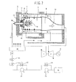
- a fuel supply system includes a fuel tank 18, a transfer pump 19, a transfer pressure control valve 20, a high pressure pump 21, a pressure control valve 22, a fuel shutoff valve 24, a flow rate control valve 23, a flow divider 26, a fuel flowmeter 25, and a fuel line 17.
- the pressure of the liquid fuel is boosted by the transfer pump 19 and the high pressure pump 21, and is set to a predetermined pressure by the pressure control valve 22 disposed in a bypass line of the high pressure pump 21.
- the liquid fuel having the boosted pressure passes through the flow rate control valve 23 having a valve opening controlled to a predetermined value, the fuel shutoff valve 24, and the fuel flowmeter 25. Thereafter, the liquid fuel is distributed to respective combustors by the flow divider 26 and is supplied to the liquid fuel nozzle 9.
- Fig. 2 shows details of the fuel supply system for the liquid fuel nozzle 9.
- the liquid fuel nozzle 9 according to this first embodiment is divided into a pilot system which ensures superior atomization performance under the condition of low fuel flow rate such as in the ignition stage, and a main system which enables the fuel to be jetted under the condition of large fuel flow rate, such as the condition of high load, without excessively raising the supply pressure.
- a pressurization valve 29 is disposed in the downstream side of a main flow path 35, and the main flow path 35 is joined with a pilot flow path 34 at a distribution pipe 36 disposed upstream of the main flow path 35.
- a check valve 28 is disposed upstream of the distribution pipe 36 and is connected to the fuel supply system including the above-described pumps, valves, etc.
- a purge air flow path 30 in the pilot system is communicated with still another end of the distribution pipe 36, and a main purge-air flow path 31 is communicated with the main flow path 35 at a position downstream of the pressurization valve 29.
- the fuel supplied from the high pressure pump 21 is distributed to the respective combustors by the flow divider 26 and is introduced to the distribution pipe 36 through the check valve 28.
- the check valve 28 serves to prevent the air for combustion, the combustion gas, the purge air, etc. from flowing backward toward the auxiliaries in the fuel supply system, such as the pumps.
- the fuel supplied to the distribution pipe 36 is distributed to the pilot flow path 34 and the main flow path 35.
- the fuel pressure acting on the pressurization valve 29 disposed midway the main flow path 35 is so low as to be not able to open the pressurization valve 29, and the fuel is supplied to only the pilot flow path 34.
- the fuel pressure acting on the pressurization valve 29 is raised up to a level sufficient to open the pressurization valve 29.
- the fuel is supplied to not only the pilot flow path 34, but also to the main flow path 35.
- the operation of stopping the gas turbine will be described in brief below.
- the fuel remaining inside the liquid fuel nozzle 9 may cause coking, i.e., a phenomenon that the fuel is carbonized by receiving heat from various components of the combustor and is fixedly stuck to the interior of the liquid fuel nozzle 9.
- the fuel injection hole is closed and the fuel cannot be jetted out of the fuel injection hole.
- the liquid fueled combustor includes means for supplying, e.g., air, for the purpose of discharging the fuel residing in the liquid fuel nozzle to a combustion chamber.
- the pilot flow path 34 and the main flow path 35 also include means for supplying purge air for the same purpose. More specifically, after the gas turbine has been stopped, purge air supplied from the purge air compressor 27 is controlled to have a predetermined pressure by the pressure control valve 39 and then supplied to the pilot and main flow paths of the liquid fuel nozzle through the pilot and main purge-air shutoff valves 37 and 38.
- the purge air is supplied to only the main flow path 35 such that the atomization of the fuel jetted out of a pilot nozzle can be assisted by the purge air jetted out of a main nozzle. Accordingly, it is possible to promote the atomization of the fuel jetted out of the pilot nozzle, and to increase reliability of ignition.
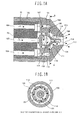
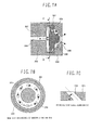
- Figs. 1A and 1B show the detailed structure of a front end portion of the dual orifice liquid fuel nozzle according to this first embodiment, i.e., the liquid fuel nozzle 9 provided with the above-described fuel supply system.
- Fig. 1A is a longitudinal sectional view of the liquid fuel nozzle 9
- Fig. 1B is a sectional view taken along line A-A in the direction of arrows in Fig. 1A .
- the liquid fuel nozzle 9 comprises a nozzle cap 100, a nozzle chip 101, a pilot chip 102, and a nozzle body 103.
- the pilot chip 102 is contained inside the nozzle chip 101.
- the nozzle chip 101 is contained inside the nozzle cap 100.
- the pilot chip 102 and the nozzle chip 102 are fixedly held together by using threads formed on the nozzle body 103 and the nozzle cap 100 for screw-in mount. Further, a main swirler 106 is disposed on the outer peripheral side of the nozzle chip 101. Incidentally, the nozzle cap 100 and the nozzle chip 101 are firmly held in place by strongly pressing the nozzle body 103 against the nozzle chip 101 at a contact surface between them.
- the nozzle body 103 has a pilot flow path 105 and a main flow path 104 which are connected respectively to pilot and main supply systems for the pilot chip 102 and the nozzle chip 101.
- the pilot chip 102 has a pilot swirl chamber 110 which is defined by the pilot chip 102 and the nozzle chip 101, and a pilot swirl hole 107 is formed to extend in the tangential direction of the pilot swirl chamber 110.
- Pilot fuel 32 supplied through the pilot flow path 105 flows into the pilot swirl hole 107 from the outer circumference of the pilot chip 102 and is given with a swirl component such that the pilot fuel 32 is swirled inside the pilot swirl chamber 110. Further, the pilot fuel 32 forms a liquid thin film along the wall surface of the pilot swirl chamber 110, and is jetted out of a pilot injection hole 108 in the form of droplets.
- Main fuel 33 supplied through the main flow path 104 passes through a main fuel supply hole 112 formed in the nozzle chip 101 and flows into the main swirler 106 through an annular flow path 113 which is defined by the nozzle cap 100 and the nozzle chip 101.
- the main fuel 33 is given with a swirl component by the main swirler 106 such that the main fuel 33 is swirled inside a main swirl chamber 111 which is defined by the inner peripheral wall of the nozzle cap 100 and the outer peripheral wall of the nozzle chip 101, followed by being jetted out of a main injection hole 109.
- the pilot injection hole 108 is disposed inside the nozzle cap 100 and has the function of jetting the pilot fuel from it. Also, the pilot injection hole 108 is defined by a space between the pilot swirl chamber 110 formed in the nozzle chip 101 and a distal end portion of the nozzle chip 101 from which is jetted the pilot fuel 32 toward the combustion chamber.
- the main injection hole 109 is disposed inside the nozzle cap 100 and has the function of jetting the main fuel from it. Also, the main injection hole 109 is defined by a space between the swirl chamber 111 for swirling the main fuel, which has been given with the swirl component by the main swirler 106, and the distal end portion of the nozzle chip 101 from which is jetted out of the pilot fuel 32 toward the combustion chamber.
- the main injection hole 109 is in the form of an annular flow path defined between the outer peripheral surface of the nozzle chip 101. and the inner peripheral surface of the nozzle cap 100.
- the swirl chamber 111 communicates the main swirler 106 and the main injection hole 109 with each other such that the main fuel having been jetted out of the annular flow path 113 is supplied to the main injection hole 109 while being swirled.
- the swirl chamber 111 is constituted as an annular flow path defined between the conically-recessed inner peripheral surface of the nozzle cap 100 and the conical outer peripheral surface of the nozzle chip 101.
- the roles of the main supply system and the pilot supply system will be described below.
- the pilot supply system serves to promote the atomization of the fuel by raising the fuel supply pressure even under the condition of low fuel flow rate such as in the ignition stage.
- the main supply system serves to enable the fuel to be jetted without excessively raising the fuel supply pressure even under the condition of high load where a large fuel flow rate is required. Under the condition of high load, therefore, a most part of the fuel flow rate is supplied through the main supply system.
- the main injection hole 109 defined by the nozzle cap 100 and the nozzle chip 101 is of a structure having a straight portion which is in the form of an annular flow path extending parallel to the axis of the liquid fuel nozzle and which has a flow path cross section not changed along the straight portion.
- the flow rates of fuel supplied to the individual combustors are desired to be even.
- the flow divider 26 for distributing the fuel to the individual combustors has a structure capable of evenly distributing the fuel.
- an allowable limit of the fuel divider 26 for ensuring even distribution is exceeded and the fuel cannot be evenly distributed in some cases.
- a most part of the fuel flow rate is occupied by the main fuel 33 jetted through the main supply system.
- the flow rate of the fuel jetted through the main supply system is dominated by the main injection hole 109 which has a minimum flow path cross section in the main supply system.
- the cross section of the main injection hole 109 is the cross section of the main supply system at the most downstream side of the pilot flow path formed by the nozzle chip 101 (i.e., at the end of the pilot injection hole 108). It is therefore important to reduce a variation in the flow path cross section of the main injection hole 109 from the viewpoint of reducing the flow deviation.
- the secondary injection hole 210 corresponding to the main injection hole 109 in the first embodiment is provided as the annular flow path constituted by the gap between the throttle portion 213 inside the secondary chip 204 and the outer peripheral wall surface of the primary chip 203.
- the outer peripheral wall surface of the primary chip 203 deciding the flow path cross section of the secondary injection hole 210 has a tapered conical geometry, and it is very difficult to control the dimensions of outer and inner peripheral surfaces of the conical primary chip 203.
- the fuel nozzle such as shown as Comparative Example 1 is assembled by inserting the nozzle block 202, the primary chip 203, and the secondary chip 204 in the nozzle cover 201, and fixedly holding them together by using threads formed on the nozzle cover 201 and the nozzle body 214 for screw-in mount.
- the nozzle cover 201 is fastened to the nozzle body 214, tightening torque is controlled.
- the tightening torque is changed, the relative positional relationship between the primary chip 203 and the secondary chip 204 in the axial direction is changed. Therefore, the flow path cross section of the secondary injection hole 210 is further changed, thus causing the flow deviation with respect to the other fuel nozzles.
- the main injection hole 109 is provided as an annular flow path having a straight portion which is defined by an inner peripheral wall 114 at the distal end of the nozzle cap 100 and an outer peripheral wall 115 at the distal end of the nozzle chip 101. That structure facilitates machining of the nozzle cap 100 and the nozzle chip 101 which decide the cross section of the main injection hole 109. Further, since machining accuracy is improved, another advantage is also obtained in that a variation in the cross section of the main injection hole caused by manufacturing errors can be reduced.
- the main swirler 106 in this first embodiment has fuel flow paths formed to extend in the direction tangential to the swirl chamber 111.
- the main swirler 106 is constituted such that the main fuel is swirled in a plane perpendicular to the axis of the pilot flow path 105.
- the direction of flow of the fuel having passed through the main swirler 106 can be given with only a swirling component in the circumferential direction of the swirl chamber 111.
- the contact distance between the swirled fuel and the flow path forming the fuel injection hole is increased.
- the increased contact distance may lead to a possibility that fuel swirl intensity is attenuated by flow path friction, a spray angle of the fuel jetted out of the fuel injection hole is narrowed, and the atomization performance is degraded.
- the swirl-component applying means of Comparative Example 2 shown in Fig. 7 particularly, the fuel swirl intensity cannot be obtained at a sufficient level and the atomization performance is further reduced in some cases. In that case, sufficient mixing between fuel and air may be impeded because of an increase in size of fuel droplets and narrowing of the spray angle.
- the fuel swirl intensity can be increased in comparison with that in Comparative Example 2.
- the main fuel can maintain a sufficient level of swirl intensity and can be jetted without degrading the atomization performance. Accordingly, even in the case of employing fuel containing a larger amount of carbon residue, particulate matters generated in the combustion process can be suppressed from becoming larger in size. As a result, it is possible to reduce the amount of discharged carbonaceous particulate matters, to suppress generation of colored smoke, and to satisfy environmental regulations.
- the advantages of the liquid fuel nozzle according to this first embodiment can also be obtained by rebuilding the existing fuel nozzle.
- the existing fuel nozzle such as shown as Comparative Example 1 can be rebuilt as follows. After removing the nozzle cover 201, the inner components, i.e., the secondary chip 204, the primary chip 203, and the nozzle block 202, are also disassembled. Then, the pilot chip 102 and the nozzle chip 101 according to this first embodiment are mounted to the nozzle body 214. Finally, the nozzle cap 100 is fitted in place.
- the advantages of this first embodiment can be obtained just by replacing some parts with no need of renewing the entire fuel nozzle.
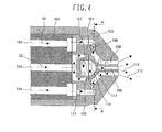
- FIG. 4 is a longitudinal sectional view of the liquid fuel nozzle according to this second embodiment.
- Basic components constituting the liquid fuel nozzle are the same as those in the first embodiment.
- the pilot injection hole 108 and the main injection hole 109 are formed such that their distal ends are located at the same position in the axial direction.
- the distal end of the pilot injection hole 108 is positioned upstream of the distal end of the main injection hole 109. This is because the first embodiment is intended to assist the atomization of the fuel jetted out of the pilot nozzle by the purge air jetted out of the main nozzle.
- the distal end of the pilot injection hole 108 By arranging the distal end of the pilot injection hole 108 to be positioned upstream of the distal end of the main injection hole 109, mixing of the purge air jetted out of the main nozzle and the fuel jetted out of the pilot nozzle can be promoted and an atomization characteristic under the condition in the ignition stage can be improved.
- fuel droplets 116 jetted out of the pilot injection hole 108 may collide against fuel droplets 117 jetted out of the main injection hole 109 under the condition of high load where the fuel is supplied through both the pilot and main injection holes and the fuel flow rate is large.
- the pilot fuel jetting position and the main fuel jetting position are set to the same point in the axial direction. Also, in this second embodiment, since the length of the flow path forming the pilot injection hole 108 is increased, the spray angle of the pilot fuel is narrowed with attenuation of the fuel swirl intensity due to the flow path friction. Therefore, the fuel droplets 116 from the pilot injection hole 108 and the fuel droplets 117 from the main injection hole 109 can be jetted in a state separated from each other. It is hence possible to avoid the main fuel droplets and the pilot fuel droplets from combining with each other, to suppress an increase in size of the fuel droplets, and to reduce the amount of carbonaceous particulate matters discharged together with exhaust gas.
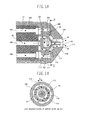
- FIG. 5A is a longitudinal sectional view of the liquid fuel nozzle according to this third embodiment
- Fig. 5B is a sectional view taken along line D-D in the direction of arrows in Fig. 5A
- Basic components in this third embodiment are the same as those in the first embodiment.
- the main fuel supply holes 112 are formed such that each hole is positioned at a shift of phase by an angle ⁇ in the circumferential direction with respect to an inlet of the main swirler 106 as a basis.
- the main fuel 33 having passed through the main fuel supply holes 112 flows into the annular flow path 113 and temporarily resides in the annular flow path 113. Thereafter, the main fuel 33 is evenly distributed to the plurality of swirl flow paths 150 constituting the main swirler 106.
- the main fuel 33 having been jetted out of the main fuel supply holes 112 can be avoided from directly flowing into the swirl flow paths 150 even under the condition of small flow rate.
- the main fuel since the main fuel temporarily resides in the annular flow path 113, it is possible to reduce the deviation in the flow rate of the fuel supplied to the swirl flow path 150, and to jet the fuel without degrading the atomization characteristic.
- the present invention can be widely applied to a variety of liquid fuel nozzles used for combusting liquid fuel in addition to that used in the gas turbine combustor.
- a liquid fuel nozzle of a gas turbine combustor comprising a nozzle cap for forming a main injection hole to jet main fuel a nozzle chip contained in said nozzle cap, including a main swirler for applying a swirl component to the main fuel and a pilot injection hole for jetting pilot fuel, and forming said main injection hole as an annular flow path in cooperation with an inner peripheral wall of said nozzle cap; and a pilot chip contained in said nozzle chip and including a pilot swirler for applying a swirl component to the pilot fuel, wherein said main injection hole for jetting the main fuel is of a structure having a straight portion which is in the form of an annular flow path extending parallel to an axis of said liquid fuel nozzle, said annular flow path having a flow path cross section not changed along said straight portion.
- the liquid fuel nozzle of the gas turbine combustor may further comprise means for applying a swirl component to the main fuel in which said liquid fuel nozzle has a swirl chamber positioned upstream of said main injection hole and promoting swirl of the main fuel, and said main swirler is positioned upstream of said swirl chamber and has a plurality of swirl flow paths extending in a direction tangential to said swirl chamber.
- the main injection hole for jetting the main fuel may preferably be formed as the annular flow path having the straight portion which is extended parallel to the axis of said liquid fuel nozzle and which has a flow path cross section not changed along said straight portion, and said main swirler for applying a swirl component to the main fuel may preferably have a plurality of swirl flow paths extending in a direction tangential to a swirl chamber.
- a distal end of said pilot injection hole may preferably be positioned at the same point as or downstream of a distal end of said main injection hole in an axial direction.
- the liquid fuel nozzle may include an annular space positioned upstream of said plurality of swirl flow paths and distributing liquid fuel to said plurality of swirl flow paths, main fuel supply holes positioned upstream of said annular space in the same number as said plurality of swirl flow paths and supplying the liquid fuel to said annular space, said plurality of swirl flow paths being preferably formed such that positions of said main injection holes and positions of inlet ends of said swirl flow paths are relatively shifted from each other by a desired angle in a circumferential direction.
- a liquid fuel nozzle may comprise a nozzle cap for forming a main injection hole to jet main fuel; a nozzle chip contained in said nozzle cap, including a main swirler for applying a swirl component to the main fuel and a pilot injection hole for jetting pilot fuel, and forming said main injection hole as an annular flow path in cooperation with an inner peripheral wall of said nozzle cap; and a pilot chip contained in said nozzle chip and including a pilot swirler for applying a swirl component to the pilot fuel, wherein said main injection hole for jetting the main fuel is of a structure having a straight portion which is in the form of an annular flow path extending parallel to an axis of said liquid fuel nozzle and which has a flow path cross section not changed along said straight portion.
- a gas turbine combustor using a liquid fuel nozzle may comprise a nozzle cap for forming a main injection hole to jet main fuel; a nozzle chip contained in said nozzle cap , including a main swirler for applying a swirl component to the main fuel and a pilot injection hole for jetting pilot fuel, and forming said main injection hole as an annular flow path in cooperation with an inner peripheral wall of said nozzle cap; and a pilot chip contained in said nozzle chip and including a pilot swirler for applying a swirl component to the pilot fuel, wherein said main injection hole for jetting the main fuel is of a structure having a straight portion which is in the form of an annular flow path extending parallel to an axis of said liquid fuel nozzle, said annular flow path having a flow path cross section not changed along said straight portion.
- a method of rebuilding a gas turbine combustor using a liquid fuel nozzle comprising a nozzle body having flow paths for main fuel and pilot fuel, and a nozzle cap containing said nozzle body therein, said nozzle body and said nozzle cap being fixed to each other by using threads formed thereon for screw-in mount, the main fuel and the pilot fuel supplied through said nozzle body being jetted out of an injection hole formed in said nozzle cap, the method may comprise a first step of removing said nozzle cap; a second step of mounting a pilot chip including a pilot swirler for applying a swirl component to the pilot fuel; a third step of mounting a nozzle chip including a main swirler for applying a swirl component to the main fuel and a pilot injection hole for jetting the pilot fuel, and forming a main injection hole as an annular flow path in cooperation with an inner peripheral wall of said nozzle cap; and a fourth step of said nozzle cap to said nozzle body such that said main injection hole for je
Landscapes
- Engineering & Computer Science (AREA)
- Chemical & Material Sciences (AREA)
- Combustion & Propulsion (AREA)
- Mechanical Engineering (AREA)
- General Engineering & Computer Science (AREA)
- Nozzles For Spraying Of Liquid Fuel (AREA)
Applications Claiming Priority (2)
| Application Number | Priority Date | Filing Date | Title |
|---|---|---|---|
| JP2005348619A JP2007155170A (ja) | 2005-12-02 | 2005-12-02 | 燃料ノズル,ガスタービン燃焼器,ガスタービン燃焼器の燃料ノズル及びガスタービン燃焼器の改造方法 |
| EP06024947A EP1793165A3 (fr) | 2005-12-02 | 2006-12-01 | Injecteur de carburant liquide, chambre de combustion de turbine à gaz, et méthode pour reconfigurer une chambre de combustion de turbine à gaz |
Related Parent Applications (1)
| Application Number | Title | Priority Date | Filing Date |
|---|---|---|---|
| EP06024947.1 Division | 2006-12-01 |
Publications (2)
| Publication Number | Publication Date |
|---|---|
| EP2385299A2 true EP2385299A2 (fr) | 2011-11-09 |
| EP2385299A3 EP2385299A3 (fr) | 2012-11-28 |
Family
ID=37757160
Family Applications (2)
| Application Number | Title | Priority Date | Filing Date |
|---|---|---|---|
| EP11162240A Withdrawn EP2385299A3 (fr) | 2005-12-02 | 2006-12-01 | Buse de fuel liquide pour chambre de combustion à gaz et procédé de reconstruction d'une turbine à gaz |
| EP06024947A Withdrawn EP1793165A3 (fr) | 2005-12-02 | 2006-12-01 | Injecteur de carburant liquide, chambre de combustion de turbine à gaz, et méthode pour reconfigurer une chambre de combustion de turbine à gaz |
Family Applications After (1)
| Application Number | Title | Priority Date | Filing Date |
|---|---|---|---|
| EP06024947A Withdrawn EP1793165A3 (fr) | 2005-12-02 | 2006-12-01 | Injecteur de carburant liquide, chambre de combustion de turbine à gaz, et méthode pour reconfigurer une chambre de combustion de turbine à gaz |
Country Status (2)
| Country | Link |
|---|---|
| EP (2) | EP2385299A3 (fr) |
| JP (1) | JP2007155170A (fr) |
Cited By (7)
| Publication number | Priority date | Publication date | Assignee | Title |
|---|---|---|---|---|
| WO2014036298A3 (fr) * | 2012-08-29 | 2014-04-24 | Snow Logic, Inc. | Buses de pulvérisation de fluide à double vecteur modulaires |
| WO2014062076A1 (fr) * | 2012-10-17 | 2014-04-24 | Schlumberger Canada Limited | Brûleur à phases multiples |
| US10107499B2 (en) | 2014-07-31 | 2018-10-23 | General Electric Company | Fuel plenum for a fuel nozzle and method of making same |
| CN108731250A (zh) * | 2018-06-08 | 2018-11-02 | 南通劲凌智能科技有限公司 | 一种液体食品加热设备及其加热方法 |
| CN108981165A (zh) * | 2018-06-08 | 2018-12-11 | 南通劲凌智能科技有限公司 | 一种流质食品匀热装置及其方法 |
| FR3132649A1 (fr) * | 2022-02-16 | 2023-08-18 | Solcera | Buse de pulvérisation à jet conique |
| WO2024020253A3 (fr) * | 2022-02-18 | 2024-05-23 | Woodward, Inc. | Injecteur de carburant multiphase |
Families Citing this family (25)
| Publication number | Priority date | Publication date | Assignee | Title |
|---|---|---|---|---|
| JP4959523B2 (ja) * | 2007-11-29 | 2012-06-27 | 株式会社日立製作所 | 燃焼装置,燃焼装置の改造方法及び燃焼装置の燃料噴射方法 |
| WO2009149990A1 (fr) * | 2008-06-09 | 2009-12-17 | Siemens Aktiengesellschaft | Procédé de rinçage d'un système d'alimentation en combustible d'une turbine à gaz et système d'alimentation en combustible associé |
| FR2938048B1 (fr) * | 2008-11-06 | 2015-03-06 | Ge Energy Products France Snc | Systeme et procede de lavage et purge a l'eau du circuit combustible liquide d'une turbine |
| US8161751B2 (en) * | 2009-04-30 | 2012-04-24 | General Electric Company | High volume fuel nozzles for a turbine engine |
| CH702598B1 (de) * | 2010-01-29 | 2013-12-13 | Alstom Technology Ltd | Einspritzdüse sowie Verfahren zum Betrieb einer solchen Einspritzdüse. |
| JP5571197B2 (ja) * | 2010-10-28 | 2014-08-13 | 三菱重工業株式会社 | ガスタービンおよびこれを備えたガスタービンプラント |
| US9745936B2 (en) * | 2012-02-16 | 2017-08-29 | Delavan Inc | Variable angle multi-point injection |
| JP5967974B2 (ja) * | 2012-02-28 | 2016-08-10 | 三菱日立パワーシステムズ株式会社 | パイロットノズル、これを備えたガスタービン燃焼器およびガスタービン |
| JP5618337B2 (ja) | 2012-02-28 | 2014-11-05 | 三菱日立パワーシステムズ株式会社 | ガスタービン燃焼器 |
| US10556246B2 (en) | 2012-03-28 | 2020-02-11 | Gf Corporation | Liquid ejecting device and method of liquid ejection |
| JP6086860B2 (ja) | 2013-11-29 | 2017-03-01 | 三菱日立パワーシステムズ株式会社 | ノズル、燃焼器、及びガスタービン |
| EP3143334B1 (fr) | 2014-05-12 | 2020-08-12 | General Electric Company | Cartouche de combustible liquide pour la formation de film |
| JP6804755B2 (ja) * | 2015-11-26 | 2020-12-23 | ウエムラ技研株式会社 | 渦巻型噴射ノズル |
| US11149950B2 (en) * | 2018-06-11 | 2021-10-19 | Woodward, Inc. | Pre-swirl pressure atomizing tip |
| RU189000U1 (ru) * | 2018-10-09 | 2019-05-06 | Федеральное государственное бюджетное образовательное Учреждение высшего образования "Воронежский государственный аграрный университет имени императора Петра 1" (ФГБОУ ВО Воронежский ГАУ) | Центробежная форсунка |
| RU188999U1 (ru) * | 2018-10-09 | 2019-05-06 | Федеральное государственное бюджетное образовательное Учреждение высшего образования "Воронежский государственный аграрный университет имени императора Петра 1" (ФГБОУ ВО Воронежский ГАУ) | Многотопливная форсунка |
| US11378040B2 (en) * | 2018-11-15 | 2022-07-05 | Stratolaunch, Llc | Swirl preburner system and method |
| WO2021079657A1 (fr) * | 2019-10-23 | 2021-04-29 | 株式会社Ihi | Injecteur de combustible liquide |
| RU2763964C1 (ru) * | 2019-12-30 | 2022-01-11 | Публичное акционерное общество "ОДК-Кузнецов" (ПАО "ОДК-Кузнецов") | Двухконтурная горелка малоэмиссионной камеры сгорания газотурбинного двигателя |
| RU2744963C1 (ru) * | 2020-06-09 | 2021-03-17 | Акционерное общество "Металлист-Самара" | Камера сгорания газотурбинной установки с выносными жаровыми трубами и малоэмиссионным горелочным устройством |
| WO2022042270A1 (fr) * | 2020-08-31 | 2022-03-03 | 重庆海尔滚筒洗衣机有限公司 | Structure de buse, dispositif d'alimentation en additif et machine à laver |
| CN112780416A (zh) * | 2021-01-29 | 2021-05-11 | 安徽应流航空科技有限公司 | 一种主燃油分配结构 |
| CN115263560A (zh) * | 2022-07-08 | 2022-11-01 | 上海和兰透平动力技术有限公司 | 液体燃料分配槽 |
| US12092331B2 (en) | 2022-11-23 | 2024-09-17 | Woodward, Inc. | Tangential pressure atomizing tip without feed chamber |
| US20250092827A1 (en) * | 2023-09-14 | 2025-03-20 | Pratt & Whitney Canada Corp. | Fuel Nozzle for an Aircraft Engine |
Citations (1)
| Publication number | Priority date | Publication date | Assignee | Title |
|---|---|---|---|---|
| JPH0762522B2 (ja) | 1986-12-15 | 1995-07-05 | 帝人製機株式会社 | ガスタ−ビンエンジンの複式燃料噴射ノズル |
Family Cites Families (10)
| Publication number | Priority date | Publication date | Assignee | Title |
|---|---|---|---|---|
| US2954172A (en) * | 1958-09-10 | 1960-09-27 | Gen Motors Corp | Liquid spray nozzle |
| US3758259A (en) * | 1971-11-26 | 1973-09-11 | J Voorheis | Methods for preparing fuels and also for thereafter feeding them into furnaces and burning them therein |
| US3785570A (en) * | 1972-08-30 | 1974-01-15 | Us Army | Dual orifice fuel nozzle with air-assisted primary at low flow rates |
| JPH0228923U (fr) * | 1988-08-04 | 1990-02-23 | ||
| JPH0740820Y2 (ja) * | 1989-02-07 | 1995-09-20 | トヨタ自動車株式会社 | ガスタービンの燃料供給装置 |
| US5086979A (en) * | 1989-07-07 | 1992-02-11 | Fuel Systems Textron Inc. | Small airblast fuel nozzle with high efficiency inner air swirler |
| DE19730617A1 (de) * | 1997-07-17 | 1999-01-21 | Abb Research Ltd | Druckzerstäuberdüse |
| FR2772118B1 (fr) * | 1997-12-05 | 2001-08-17 | Saint Gobain Vitrage | Procede de combustion et bruleur a pulverisation de combustible mettant en oeuvre un tel procede |
| US6289676B1 (en) * | 1998-06-26 | 2001-09-18 | Pratt & Whitney Canada Corp. | Simplex and duplex injector having primary and secondary annular lud channels and primary and secondary lud nozzles |
| JP3960222B2 (ja) * | 2002-12-27 | 2007-08-15 | 株式会社日立製作所 | ガスタービン燃焼器及びガスタービン燃焼器用燃料噴射ノズルとガスタービン燃焼器の燃料噴射方法 |
-
2005
- 2005-12-02 JP JP2005348619A patent/JP2007155170A/ja active Pending
-
2006
- 2006-12-01 EP EP11162240A patent/EP2385299A3/fr not_active Withdrawn
- 2006-12-01 EP EP06024947A patent/EP1793165A3/fr not_active Withdrawn
Patent Citations (1)
| Publication number | Priority date | Publication date | Assignee | Title |
|---|---|---|---|---|
| JPH0762522B2 (ja) | 1986-12-15 | 1995-07-05 | 帝人製機株式会社 | ガスタ−ビンエンジンの複式燃料噴射ノズル |
Cited By (15)
| Publication number | Priority date | Publication date | Assignee | Title |
|---|---|---|---|---|
| RU2660856C2 (ru) * | 2012-08-29 | 2018-07-10 | Сноу Лоджик, Инк. | Модульные двухвекторные распылительные сопла для текучей среды |
| WO2014036298A3 (fr) * | 2012-08-29 | 2014-04-24 | Snow Logic, Inc. | Buses de pulvérisation de fluide à double vecteur modulaires |
| GB2522139B (en) * | 2012-10-17 | 2020-04-15 | Schlumberger Holdings | Multiphase burner and method for flaring a wet gas flow |
| US20150330626A1 (en) * | 2012-10-17 | 2015-11-19 | Schlumberger Technology Corporation | Multiphase burner |
| GB2522139A (en) * | 2012-10-17 | 2015-07-15 | Schlumberger Holdings | Multiphase burner |
| US10288283B2 (en) | 2012-10-17 | 2019-05-14 | Schlumberger Technology Corporation | Multiphase burner |
| WO2014062076A1 (fr) * | 2012-10-17 | 2014-04-24 | Schlumberger Canada Limited | Brûleur à phases multiples |
| US10107499B2 (en) | 2014-07-31 | 2018-10-23 | General Electric Company | Fuel plenum for a fuel nozzle and method of making same |
| CN108731250A (zh) * | 2018-06-08 | 2018-11-02 | 南通劲凌智能科技有限公司 | 一种液体食品加热设备及其加热方法 |
| CN108981165A (zh) * | 2018-06-08 | 2018-12-11 | 南通劲凌智能科技有限公司 | 一种流质食品匀热装置及其方法 |
| CN108731250B (zh) * | 2018-06-08 | 2020-11-13 | 上海薄荷信息科技有限公司 | 一种液体食品加热设备及其加热方法 |
| FR3132649A1 (fr) * | 2022-02-16 | 2023-08-18 | Solcera | Buse de pulvérisation à jet conique |
| EP4230301A1 (fr) * | 2022-02-16 | 2023-08-23 | Solcera | Buse de pulverisation a jet conique |
| WO2024020253A3 (fr) * | 2022-02-18 | 2024-05-23 | Woodward, Inc. | Injecteur de carburant multiphase |
| US12331933B2 (en) | 2022-02-18 | 2025-06-17 | Woodward, Inc. | Multiphase fuel injector |
Also Published As
| Publication number | Publication date |
|---|---|
| EP1793165A2 (fr) | 2007-06-06 |
| EP2385299A3 (fr) | 2012-11-28 |
| JP2007155170A (ja) | 2007-06-21 |
| EP1793165A3 (fr) | 2009-02-25 |
Similar Documents
| Publication | Publication Date | Title |
|---|---|---|
| EP2385299A2 (fr) | Buse de fuel liquide pour chambre de combustion à gaz et procédé de reconstruction d'une turbine à gaz | |
| EP1655456B1 (fr) | Installation de production d'énergie à turbine à gaz | |
| CN105698175B (zh) | 具有一体式液体蒸发器的预混喷嘴 | |
| US7610759B2 (en) | Combustor and combustion method for combustor | |
| EP2208927B1 (fr) | Brûleur d'une turbine à gaz | |
| CN106415132B (zh) | 燃烧装置的燃烧器布置 | |
| US9027349B2 (en) | Gas turbine gaseous fuel injection system | |
| CA2578565C (fr) | Methode et dispositif pour turbines a gaz | |
| EP2481985B1 (fr) | Ensemble d'injecteur de carburant | |
| US10731862B2 (en) | Systems and methods for a multi-fuel premixing nozzle with integral liquid injectors/evaporators | |
| JP2005106305A (ja) | 燃料燃焼用ノズルおよびガスタービン燃焼器の燃料供給方法 | |
| JP4659543B2 (ja) | ガスタービン燃焼器、その燃料のカーボン化防止方法及びパージ方法 | |
| JP4400314B2 (ja) | ガスタービン燃焼器及びガスタービン燃焼器の燃料供給方法 | |
| JP4719704B2 (ja) | ガスタービン燃焼器 | |
| JP5610446B2 (ja) | ガスタービン燃焼器 | |
| JP4977522B2 (ja) | ガスタービン燃焼器 | |
| JP2008031847A (ja) | ガスタービン燃焼器とその運転方法、及びガスタービン燃焼器の改造方法 | |
| JP5627831B2 (ja) | タービンエンジン内に流体を噴射するための装置 | |
| EP4411237B1 (fr) | Injecteur avec disque pour moteur à turbine à gaz à hydrogène | |
| EP4513089B1 (fr) | Chambre de combustion | |
| US20260063298A1 (en) | Co-firing combustor with gas fuel and liquid ammonia | |
| JP2004278875A (ja) | ガスタービン燃焼器と燃料ノズル及びガスタービン燃焼器の燃料噴射方法 | |
| KR20020074690A (ko) | 스월러를 구비한 연료 인젝터 |
Legal Events
| Date | Code | Title | Description |
|---|---|---|---|
| 17P | Request for examination filed |
Effective date: 20110801 |
|
| AC | Divisional application: reference to earlier application |
Ref document number: 1793165 Country of ref document: EP Kind code of ref document: P |
|
| AK | Designated contracting states |
Kind code of ref document: A2 Designated state(s): DE FR GB |
|
| PUAI | Public reference made under article 153(3) epc to a published international application that has entered the european phase |
Free format text: ORIGINAL CODE: 0009012 |
|
| PUAL | Search report despatched |
Free format text: ORIGINAL CODE: 0009013 |
|
| RIC1 | Information provided on ipc code assigned before grant |
Ipc: F23D 11/24 20060101ALI20121019BHEP Ipc: F23D 11/38 20060101AFI20121019BHEP |
|
| AK | Designated contracting states |
Kind code of ref document: A3 Designated state(s): DE FR GB |
|
| RIC1 | Information provided on ipc code assigned before grant |
Ipc: F23D 11/24 20060101ALI20121019BHEP Ipc: F23D 11/38 20060101AFI20121019BHEP |
|
| STAA | Information on the status of an ep patent application or granted ep patent |
Free format text: STATUS: THE APPLICATION HAS BEEN WITHDRAWN |
|
| 18W | Application withdrawn |
Effective date: 20141219 |