EP2385302A1 - Kaminsystem - Google Patents
Kaminsystem Download PDFInfo
- Publication number
- EP2385302A1 EP2385302A1 EP10004811A EP10004811A EP2385302A1 EP 2385302 A1 EP2385302 A1 EP 2385302A1 EP 10004811 A EP10004811 A EP 10004811A EP 10004811 A EP10004811 A EP 10004811A EP 2385302 A1 EP2385302 A1 EP 2385302A1
- Authority
- EP
- European Patent Office
- Prior art keywords
- chimney
- pipe
- combustion air
- combustion
- exhaust
- Prior art date
- Legal status (The legal status is an assumption and is not a legal conclusion. Google has not performed a legal analysis and makes no representation as to the accuracy of the status listed.)
- Granted
Links
- 238000002485 combustion reaction Methods 0.000 claims abstract description 140
- 239000000567 combustion gas Substances 0.000 claims abstract description 33
- 239000000463 material Substances 0.000 claims abstract description 10
- 238000000034 method Methods 0.000 claims abstract description 9
- 239000002033 PVDF binder Substances 0.000 claims abstract description 7
- 239000004033 plastic Substances 0.000 claims abstract description 7
- 229920003023 plastic Polymers 0.000 claims abstract description 7
- 239000002253 acid Substances 0.000 claims abstract description 6
- 229920002981 polyvinylidene fluoride Polymers 0.000 claims abstract description 6
- 125000006850 spacer group Chemical group 0.000 claims description 8
- XAGFODPZIPBFFR-UHFFFAOYSA-N aluminium Chemical compound [Al] XAGFODPZIPBFFR-UHFFFAOYSA-N 0.000 claims description 6
- 229910052782 aluminium Inorganic materials 0.000 claims description 6
- 229910052500 inorganic mineral Inorganic materials 0.000 claims description 4
- 239000011707 mineral Substances 0.000 claims description 4
- 239000004575 stone Substances 0.000 claims description 4
- 238000009833 condensation Methods 0.000 description 14
- 230000005494 condensation Effects 0.000 description 14
- 238000010438 heat treatment Methods 0.000 description 10
- MWUXSHHQAYIFBG-UHFFFAOYSA-N nitrogen oxide Inorganic materials O=[N] MWUXSHHQAYIFBG-UHFFFAOYSA-N 0.000 description 9
- CURLTUGMZLYLDI-UHFFFAOYSA-N Carbon dioxide Chemical compound O=C=O CURLTUGMZLYLDI-UHFFFAOYSA-N 0.000 description 8
- 238000006386 neutralization reaction Methods 0.000 description 8
- 238000009418 renovation Methods 0.000 description 8
- 239000003546 flue gas Substances 0.000 description 7
- 239000007789 gas Substances 0.000 description 7
- QAOWNCQODCNURD-UHFFFAOYSA-N Sulfuric acid Chemical compound OS(O)(=O)=O QAOWNCQODCNURD-UHFFFAOYSA-N 0.000 description 6
- 239000000446 fuel Substances 0.000 description 6
- 238000009423 ventilation Methods 0.000 description 6
- XLYOFNOQVPJJNP-UHFFFAOYSA-N water Chemical compound O XLYOFNOQVPJJNP-UHFFFAOYSA-N 0.000 description 6
- 229930195733 hydrocarbon Natural products 0.000 description 5
- 150000002430 hydrocarbons Chemical class 0.000 description 5
- IJGRMHOSHXDMSA-UHFFFAOYSA-N Atomic nitrogen Chemical compound N#N IJGRMHOSHXDMSA-UHFFFAOYSA-N 0.000 description 4
- UGFAIRIUMAVXCW-UHFFFAOYSA-N Carbon monoxide Chemical compound [O+]#[C-] UGFAIRIUMAVXCW-UHFFFAOYSA-N 0.000 description 4
- 229910002092 carbon dioxide Inorganic materials 0.000 description 4
- 239000001569 carbon dioxide Substances 0.000 description 4
- 238000005516 engineering process Methods 0.000 description 4
- 238000009434 installation Methods 0.000 description 4
- OKTJSMMVPCPJKN-UHFFFAOYSA-N Carbon Chemical compound [C] OKTJSMMVPCPJKN-UHFFFAOYSA-N 0.000 description 3
- 239000004071 soot Substances 0.000 description 3
- 239000000126 substance Substances 0.000 description 3
- VTYYLEPIZMXCLO-UHFFFAOYSA-L Calcium carbonate Chemical compound [Ca+2].[O-]C([O-])=O VTYYLEPIZMXCLO-UHFFFAOYSA-L 0.000 description 2
- 230000002378 acidificating effect Effects 0.000 description 2
- 239000011449 brick Substances 0.000 description 2
- 229910052799 carbon Inorganic materials 0.000 description 2
- 239000000356 contaminant Substances 0.000 description 2
- 238000011109 contamination Methods 0.000 description 2
- 238000001816 cooling Methods 0.000 description 2
- 230000001419 dependent effect Effects 0.000 description 2
- 239000003344 environmental pollutant Substances 0.000 description 2
- 239000008187 granular material Substances 0.000 description 2
- 239000004519 grease Substances 0.000 description 2
- 239000007788 liquid Substances 0.000 description 2
- VNWKTOKETHGBQD-UHFFFAOYSA-N methane Chemical compound C VNWKTOKETHGBQD-UHFFFAOYSA-N 0.000 description 2
- 229910052757 nitrogen Inorganic materials 0.000 description 2
- 231100000719 pollutant Toxicity 0.000 description 2
- 230000000717 retained effect Effects 0.000 description 2
- 239000010865 sewage Substances 0.000 description 2
- XTQHKBHJIVJGKJ-UHFFFAOYSA-N sulfur monoxide Chemical class S=O XTQHKBHJIVJGKJ-UHFFFAOYSA-N 0.000 description 2
- 229910052815 sulfur oxide Inorganic materials 0.000 description 2
- 235000008733 Citrus aurantifolia Nutrition 0.000 description 1
- NINIDFKCEFEMDL-UHFFFAOYSA-N Sulfur Chemical compound [S] NINIDFKCEFEMDL-UHFFFAOYSA-N 0.000 description 1
- 235000011941 Tilia x europaea Nutrition 0.000 description 1
- 150000007513 acids Chemical class 0.000 description 1
- 238000003915 air pollution Methods 0.000 description 1
- 229910000019 calcium carbonate Inorganic materials 0.000 description 1
- 238000004140 cleaning Methods 0.000 description 1
- 239000003245 coal Substances 0.000 description 1
- 238000010276 construction Methods 0.000 description 1
- 238000005260 corrosion Methods 0.000 description 1
- 230000007797 corrosion Effects 0.000 description 1
- 238000011161 development Methods 0.000 description 1
- 230000018109 developmental process Effects 0.000 description 1
- 239000000428 dust Substances 0.000 description 1
- 230000000694 effects Effects 0.000 description 1
- 238000000605 extraction Methods 0.000 description 1
- 238000010304 firing Methods 0.000 description 1
- 239000002803 fossil fuel Substances 0.000 description 1
- 239000004571 lime Substances 0.000 description 1
- 230000014759 maintenance of location Effects 0.000 description 1
- 239000003345 natural gas Substances 0.000 description 1
- 239000003921 oil Substances 0.000 description 1
- 230000035515 penetration Effects 0.000 description 1
- 238000000746 purification Methods 0.000 description 1
- 238000011084 recovery Methods 0.000 description 1
- 229910001220 stainless steel Inorganic materials 0.000 description 1
- 239000010935 stainless steel Substances 0.000 description 1
- 230000035882 stress Effects 0.000 description 1
- 229910052717 sulfur Inorganic materials 0.000 description 1
- 239000011593 sulfur Substances 0.000 description 1
- 230000008646 thermal stress Effects 0.000 description 1
Images

Classifications
-
- F—MECHANICAL ENGINEERING; LIGHTING; HEATING; WEAPONS; BLASTING
- F23—COMBUSTION APPARATUS; COMBUSTION PROCESSES
- F23J—REMOVAL OR TREATMENT OF COMBUSTION PRODUCTS OR COMBUSTION RESIDUES; FLUES
- F23J13/00—Fittings for chimneys or flues
- F23J13/02—Linings; Jackets; Casings
- F23J13/025—Linings; Jackets; Casings composed of concentric elements, e.g. double walled
-
- F—MECHANICAL ENGINEERING; LIGHTING; HEATING; WEAPONS; BLASTING
- F23—COMBUSTION APPARATUS; COMBUSTION PROCESSES
- F23J—REMOVAL OR TREATMENT OF COMBUSTION PRODUCTS OR COMBUSTION RESIDUES; FLUES
- F23J11/00—Devices for conducting smoke or fumes, e.g. flues
- F23J11/12—Smoke conduit systems for factories or large buildings
-
- F—MECHANICAL ENGINEERING; LIGHTING; HEATING; WEAPONS; BLASTING
- F23—COMBUSTION APPARATUS; COMBUSTION PROCESSES
- F23L—SUPPLYING AIR OR NON-COMBUSTIBLE LIQUIDS OR GASES TO COMBUSTION APPARATUS IN GENERAL ; VALVES OR DAMPERS SPECIALLY ADAPTED FOR CONTROLLING AIR SUPPLY OR DRAUGHT IN COMBUSTION APPARATUS; INDUCING DRAUGHT IN COMBUSTION APPARATUS; TOPS FOR CHIMNEYS OR VENTILATING SHAFTS; TERMINALS FOR FLUES
- F23L17/00—Inducing draught; Tops for chimneys or ventilating shafts; Terminals for flues
- F23L17/02—Tops for chimneys or ventilating shafts; Terminals for flues
- F23L17/04—Balanced-flue arrangements, i.e. devices which combine air inlet to combustion unit with smoke outlet
-
- F—MECHANICAL ENGINEERING; LIGHTING; HEATING; WEAPONS; BLASTING
- F23—COMBUSTION APPARATUS; COMBUSTION PROCESSES
- F23L—SUPPLYING AIR OR NON-COMBUSTIBLE LIQUIDS OR GASES TO COMBUSTION APPARATUS IN GENERAL ; VALVES OR DAMPERS SPECIALLY ADAPTED FOR CONTROLLING AIR SUPPLY OR DRAUGHT IN COMBUSTION APPARATUS; INDUCING DRAUGHT IN COMBUSTION APPARATUS; TOPS FOR CHIMNEYS OR VENTILATING SHAFTS; TERMINALS FOR FLUES
- F23L17/00—Inducing draught; Tops for chimneys or ventilating shafts; Terminals for flues
- F23L17/02—Tops for chimneys or ventilating shafts; Terminals for flues
- F23L17/14—Draining devices
-
- F—MECHANICAL ENGINEERING; LIGHTING; HEATING; WEAPONS; BLASTING
- F23—COMBUSTION APPARATUS; COMBUSTION PROCESSES
- F23J—REMOVAL OR TREATMENT OF COMBUSTION PRODUCTS OR COMBUSTION RESIDUES; FLUES
- F23J2213/00—Chimneys or flues
- F23J2213/10—Linings
- F23J2213/101—Fastening means therefor
-
- F—MECHANICAL ENGINEERING; LIGHTING; HEATING; WEAPONS; BLASTING
- F23—COMBUSTION APPARATUS; COMBUSTION PROCESSES
- F23J—REMOVAL OR TREATMENT OF COMBUSTION PRODUCTS OR COMBUSTION RESIDUES; FLUES
- F23J2213/00—Chimneys or flues
- F23J2213/30—Specific materials
- F23J2213/301—Specific materials flexible
-
- F—MECHANICAL ENGINEERING; LIGHTING; HEATING; WEAPONS; BLASTING
- F23—COMBUSTION APPARATUS; COMBUSTION PROCESSES
- F23J—REMOVAL OR TREATMENT OF COMBUSTION PRODUCTS OR COMBUSTION RESIDUES; FLUES
- F23J2213/00—Chimneys or flues
- F23J2213/30—Specific materials
- F23J2213/302—Specific materials plastic
-
- F—MECHANICAL ENGINEERING; LIGHTING; HEATING; WEAPONS; BLASTING
- F23—COMBUSTION APPARATUS; COMBUSTION PROCESSES
- F23J—REMOVAL OR TREATMENT OF COMBUSTION PRODUCTS OR COMBUSTION RESIDUES; FLUES
- F23J2900/00—Special arrangements for conducting or purifying combustion fumes; Treatment of fumes or ashes
- F23J2900/13004—Water draining devices associated with flues
-
- F—MECHANICAL ENGINEERING; LIGHTING; HEATING; WEAPONS; BLASTING
- F23—COMBUSTION APPARATUS; COMBUSTION PROCESSES
- F23J—REMOVAL OR TREATMENT OF COMBUSTION PRODUCTS OR COMBUSTION RESIDUES; FLUES
- F23J2900/00—Special arrangements for conducting or purifying combustion fumes; Treatment of fumes or ashes
- F23J2900/13021—Means for supporting the lining of conducting means, e.g. ducts or chimneys
Definitions
- the invention relates to a fireplace system for combustion plants, in particular for gas or oil-fired heating systems.
- the chimney system is used for the removal of combustion gases, the supply of combustion air and for the removal of used room air.
- Such a fireplace system can also be referred to as an air-exhaust-exhaust system.
- hydrocarbons are derived from living matter, they contain a large amount of carbon and in smaller quantities a variety of other substances, such as sulfur and nitrogen.
- the combustion gas therefore contains in addition to water vapor, carbon dioxide, soot, sulfur oxides and nitrogen oxides and sulfuric acid.
- the nitrogen oxides arise largely from nitrogen, which also comes from the combustion air.
- water vapor, soot, sulfur oxides and sulfuric acid can be at least partially retained by suitable means but with high technical and energy expenditure.
- chimneys made of high-quality plastics such as PVDF (polyvinylidene fluoride) are used, which are able to withstand the action of the condensate.
- PVDF polyvinylidene fluoride
- a condensation of the combustion gases is deliberately allowed and thereby recovered a large part of the energy which is bound in the combustion gas.
- condensation chimneys a large part of the pollutants contained in the flue gas, polluting substances such as sulfuric acid, unburned hydrocarbons, water vapor and soot can be retained in the chimney pipe.
- the boiler exhaust temperature can be lowered to a minimum.
- the temperature of the exhaust gas when leaving the boiler only about 30-40 ° C and in the low-temperature technology about 90-140 ° C amount.
- a reduction of the flue gas temperature means a more efficient use of the heat of combustion for heating the heat carrier (usually water) and a saving of expensive fuel.
- Condensation chimneys allow for the first time to operate the boiler with the minimum boiler water temperature specified by the manufacturer, from which then the lowest possible exhaust gas temperature and from this again the highest possible efficiency of the firing plant results.
- this technique allows significantly increased burner run times, avoiding start up and shutdown losses (e.g., factor 10) of the equipment, and minimizing material stress.
- the thus preheated fresh combustion air is then used to operate the boiler and thus reused the heat of the combustion gases.
- the condensation of the combustion gases produces a liquid condensate which, depending on the fuel, is highly acidic and flows down the chimney walls.
- a neutralization tank which binds and neutralizes the pollutants.
- This neutralization tank usually contains an activated carbon filter and a neutralization granules, which neutralizes the acids of the condensate.
- the neutralization granules used are either chemically produced calcium carbonate or natural lime. After neutralization, pure harmless water is released from the condensate, which is sent to the sewage system. For example, one liter of burnt oil produces 0.8 liters of condensate that is not released into the environment as exhaust gas.
- the DE 3 421 112 A1 describes a condensation chimney, which is used for the application of the technique of cold, wet, condensing chimney.
- This fireplace is most effective in terms of heat recovery and combustion gas purification in heating systems for smaller buildings.
- Such a fireplace system is made of individual welded together plastic pipes and is only suitable for a fireplace.
- a great energy saving potential is also given in multi-storey buildings with multi-storey heating, in which several boilers or heaters are connected in the form of a cascade to a common fireplace, which, in order to avoid sooting of the fireplace, must be operated at very high exhaust gas temperatures.
- the invention therefore has as its object to provide a condensation chimney system, in particular for multi-storey buildings with multi-storey heating, which recovers heat energy and substantially improves the installation and capital expenditure of such a condensation chimney system.
- a chimney system comprising a chimney pipe for removing combustion gases, a combustion air pipe for supplying combustion air and an exhaust duct for removing room air, wherein the chimney pipe is disposed inside the combustion air pipe and the combustion air pipe is disposed inside the exhaust duct ,
- a proper removal of the combustion gases through the chimney pipe is ensured, whereby the arrangement of the chimney pipe in a combustion air pipe, the combustion air are preheated by the hot combustion gases and thus the heat energy is reused in the flue gases.
- spent air in a duct exhausted room air can be removed from the building, in which case the combustion air, which supplied the heater is preheated by the warm spent room air.
- the heat energy which is in the used room air, recovered through the combustion air in part.
- the fireplace system therefore three different functions are carried out in an energetically advantageous manner, namely first, the removal of the combustion gases from the corresponding boiler, second, a controlled supply of combustion air to the boiler, as is necessary for a room air independent operation of the boiler, and thirdly, a controlled discharge of spent room air via an exhaust duct, are arranged in the combustion air pipe and chimney pipe.
- a corresponding Kaminsan ist must be carried out and there must be no additional Zu Kunststoff- or exhaust ducts are laid in the building.
- the installation effort is reduced considerably, which is very advantageous especially for renovations of apartment buildings.
- the existing there already existing fireplace can be used as an exhaust duct for the removal of the room air.
- the chimney system is designed as a countercurrent heat exchanger, wherein the warm combustion gases through the chimney pipe transfer heat to the cold combustion air and heat them up and wherein also transfers the warm room air through the combustion air pipe heat to the cold combustion air.
- the chimney pipe made of an acid-resistant plastic material, preferably made of PVDF.
- an acid-resistant plastic material preferably PVDF
- the chimney pipe can easily with low exhaust gas temperatures be operated so that the boiler can be operated in condensing operation.
- the warm flue gas condenses in the chimney pipe and the condensate runs down inside the chimney pipe. Due to the condensation, therefore, further heat can be recovered.
- the chimney pipe sections of flexible tube Preferably, the chimney pipe sections of flexible tube.
- a flexible chimney pipe can compensate for length and position inaccuracies, which brings advantages in particular in the renovation of existing older chimneys. Furthermore, the heat transfer from the hot flue gases to the cool combustion air is particularly effective due to the increased surface area of such flexible tubes.
- the chimney pipe is arranged by means of spacers in the combustion air pipe.
- spacers are used, which are attached to the chimney pipe.
- the combustion air pipe sections of a variable-length tube preferably made of a variable-length, flexible aluminum tube.
- the combustion air pipe has sections of a variable-length pipe, in particular an aluminum flex pipe, the assembly of the fireplace system is particularly simple.
- the combustion air pipe can then be pushed together to easily assemble the chimney pipe arranged therein.
- a flexible variable-length tube provides a larger surface than a corresponding smooth rigid tube, so that the heat transfer from the warm room air to the cold combustion air is particularly effective.
- a variable-length, flexible aluminum tube compensates for assembly inaccuracies, especially in the renovation of existing fireplaces.
- the exhaust duct is formed by chimney blocks of a mineral material. Old, to be renovated chimneys usually also consist of chimney stones made of a mineral material and can serve directly as exhaust duct after a thorough cleaning.
- the chimney system has a single condensate drainage for the entire chimney system, wherein the condensate drain is connected to the lower end of the chimney pipe.
- condensate arising from the chimney pipe itself is removed from the chimney pipe itself and from the heating systems connected thereto. This eliminates separate condensate lines, separate dry siphons and individual discharges into the sewage system.
- the condensate is collected centrally on a condensate drain at the bottom of the chimney pipe and optionally introduced via a neutralization box in the sewer system.
- the chimney system further comprises an exhaust fan, which blows room air into the exhaust duct.
- an exhaust fan is provided per apartment.
- the extract air fan determines the amount of air to be exchanged in the home or building by injecting used room air into the exhaust air duct so that fresh air can flow into the building at decentralized inlet openings on the building shell.
- the chimney system thus assumes the function of a central exhaust air system.
- an exhaust air filter is arranged in front of the respective exhaust fan, which effectively filters out dusts, grease droplets and other contaminants in the room air.
- the exhaust filter may include a filter mat, which must be changed at regular intervals.
- the chimney system further comprises a connection element for connecting a heater to the chimney system, wherein the connection element has a chimney pipe tee, which is connected to the chimney pipe, and a combustion air pipe tee, which is connected to the combustion air pipe with the combustion air tube tee surrounding the chimney tee.
- a connecting element which consists of two T-pieces, wherein the chimney tee is arranged within the combustion air pipe tee, the chimney pipe and the combustion air pipe can be connected to the corresponding boilers on the respective floors of a building.
- This double tee is preferably securely fastened in the chimney stone by means of a special holder, particularly preferably by means of an expansion plug.
- both a gas-tight connection of the chimney pipe for the exhaust gases of the boiler, as well as a gas-tight connection of the combustion air pipe is given to the boiler.
- three media can be transported without any problems, for example combustion gases, combustion air and exhaust air from the building.
- the lowermost combustion air tube tee and the lowermost flue tube tee are connected to a cuff cap which closes the combustion air tube tee downwardly and provides a passageway for the flue tube.
- the cuff lid forms a seal for the combustion air after the lowest connection piece on the chimney system. It allows the passage of the chimney pipe, so that any condensate can be directed down to the single condensate drain.
- the chimney system further comprises a chimney inlet, which is connected to a lateral connection of the chimney pipe tee and is preferably arranged to fall down to the chimney pipe, and a combustion air connection pipe, which is connected to a lateral connection of the combustion air pipe tee and which surrounds the tubular chimney inlet.
- a combustion air connection pipe which is connected to a lateral connection of the combustion air pipe tee and which surrounds the tubular chimney inlet.
- condensate from the heater can also flow into the chimney pipe via a falling chimney inlet.
- a boiler connected to it is supplied with the necessary combustion air, so that it is operated room air independent.
- the fireplace system allows multiple occupancy and has a plurality of exhaust fans and / or a plurality of connection elements.
- the fireplace system can be used in particular in multi-storey housing, in a house with several floors each floor has its own heating or their own boiler, which are connected to a common fireplace system.
- the individual apartments can be centrally vented via the common fireplace system.
- the chimney system further comprises a wall panel, which provides a sealed passage for the combustion air connection pipe and at the same time an airtight connection of the exhaust fan to the exhaust duct.
- a wall panel which provides a sealed passage for the combustion air connection pipe and at the same time an airtight connection of the exhaust fan to the exhaust duct.
- the entire connection of a heater as well as the connection of the fan to the exhaust duct is made by a common wall panel, which considerably simplifies the assembly of these components.
- both the combustion air tube and the chimney pipe arranged therein can be safely and easily mounted inside the exhaust air duct. Due to the variable-length tube for Verbrennungs Kunststoffzufiihrung mounting space is created after pushing together so that the fitter can cleanly connect the chimney pipe arranged therein to other elements, such as a chimney tee, a cuff cover or a sleeve. This is particularly important because the chimney pipe and the combustion air tube is attached to the chimney stacks at least once per floor by means of the double T-pieces.
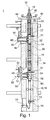
- FIG. 1 shows an overall view of a chimney system 1, comprising a flue pipe 10 for the removal of combustion gases 12, a combustion air pipe 20 for supplying combustion air 22 to the heaters (not shown) and an exhaust duct 30 for removing room air 32nd Die Figures 2-4 show details of the chimney system 1.
- the combustion air pipe 20 located within the exhaust duct 30, the combustion air pipe 20.
- the chimney pipe 10 is arranged. This can be transported through the chimney system 1, three different media, namely combustion gases 12 from the boilers, which are discharged through the chimney pipe 10 upwards, usually through the roof, in the environment.
- the combustion air 22 required for combustion of the fuel is supplied via the combustion air pipe 20 to the individual boilers room air independent.
- the chimney system 1 also serves to remove used room air 32, which is sucked by means of exhaust fans 40 from the room and discharged via the exhaust duct 30 upwards out of the building. As shown, the room air 32 exits laterally from the exhaust air duct 30 at the upper end of the chimney system 1.
- the combustion air 32 is sucked in through lateral openings 92 in a chimney closure sleeve 90 in the annular gap between the combustion air pipe 20 and the chimney pipe 10.
- the combustion gases 12 are removed from the chimney pipe 10 which extends through the chimney closure sleeve 90.
- the exhaust duct 30 is preferably made of mineral fireplace stones 34, which may also consist of an already existing in a building fireplace. In this existing chimney 34 is then a combustion air tube 20 with a chimney pipe 10 arranged therein. As the exhaust duct 30 then serves the remaining space between the chimney blocks 34 and the combustion air pipe 20. The combustion air 22 is sucked in the annular gap between the combustion air pipe 20 and chimney pipe 10.
- the chimney system 1 functions as a counterflow heat exchanger, with the warm combustion gases 12 passing heat through the chimney pipe 10 to the cold combustion air 22 which flows downwardly to the individual boilers (not shown) in the annular gap between chimney pipe 10 and combustion air pipe 20 ,
- the combustion air 22 is heated by the heat of the combustion gases 12 and thus their heat is recovered.
- the consumed, generally warm room air 32 is conveyed upwards through the exhaust air duct 30 out of the building or the individual apartments and sweeps past the combustion air pipe 20 on the outside.
- the warm room air 32 also gives off heat to the combustion air 22.
- the heat of the warm room air 32 is recovered to a large extent.
- the fireplace system 1 is designed for multiple occupancy, that is, to the fireplace system 1 more heaters or boilers can be connected. In particular, it is therefore suitable for renovations in multi-storey housing, with an existing brick fireplace 34 can be converted into a fireplace system 1 according to the invention and then a boiler can be connected to the fireplace system 1 on each floor of the building. Furthermore, the chimney system 1 is used for individual ventilation of each connected thereto projectile or each connected apartment and thus ensures a pleasant indoor climate.
- the occupants of the individual floors can regulate their heating habits individually and also choose their own ventilation habits.
- the chimney pipe 10 is preferably made of an acid-resistant plastic material, preferably polyvinylidene fluoride (PVDF). As in the Figures 1 - 4 shown, the chimney pipe 10 sections of a flexible tube 14. Spacers 16 on the outside of the chimney pipe 10 ensure that the chimney pipe 10 is arranged substantially centrally within the combustion air pipe 20.
- PVDF polyvinylidene fluoride
- the combustion air tube 20 is preferably made of a variable-length tube, preferably made of a variable-length flexible aluminum tube 20.
- Such tubes are also known by the term "Aluminumflexrohr” and are used in ventilation technology. They are characterized by the fact that they can be laid flexibly and their length can be changed by preferably 100%. Such flexible aluminum tubes can be pulled apart when compared to the collapsed state reach twice the length.
- connection elements 50 which each have a chimney pipe T-piece 52 and a combustion air pipe T-piece 54.
- the combustion air tube T-piece 54 surrounds the chimney pipe T-piece 52 and is secured therein.
- the chimney pipe T-piece 52 is connected to two parts of a chimney pipe 10 and ensures that, from the side, combustion gases 12 can be introduced into the chimney pipe 10.
- a tubular chimney inlet 60 is connected to a lateral connection of the chimney pipe T-piece 52.
- the chimney inlet 60 to the chimney pipe tee 52 is arranged slightly falling, so that condensate, which may be incurred in the boiler, can flow directly into the chimney pipe 10, which also fills the common siphon on the condensate drain 70 safer and prevents the same.
- the combustion air tube tee 54 is interposed between two parts of the combustion air tube 20 and provides a side port for combustion air 22 ready.
- a combustion air connection pipe 90 which surrounds the chimney introduction 60 is connected to the lateral connection of the combustion air tube T-piece 54. Via the annular gap between the combustion air connection pipe 90 and the chimney inlet 60, the combustion air 22 required for combustion of the fuel in a heater is supplied to the boiler (not shown).
- an electric exhaust fan 40 In order to remove used room air 32 from the corresponding building or the apartment, it is blown into the exhaust air duct 30 by means of an electric exhaust fan 40.
- the delivery rate of the exhaust fan 40 is preferably adjustable, so that the air exchange in the building or in the corresponding apartment can be set individually.
- an exhaust filter 42 is connected in front of the exhaust fan 40.
- the exhaust filter 42 prevents penetration of dust, grease droplets or other contaminants in the exhaust duct 30.
- a filter mat of the filter class F4 is used as an exhaust filter, which should be replaced every six months depending on the pollution.
- the exhaust fan 40 is attached to a wall panel 56, which seals an opening in the chimney shaft 30.
- the combustion air connection pipe 90 and the fireplace inlet 60 is also guided through this wall panel, so that only one connection point must be provided for connecting the heating of a dwelling to the chimney system 1.
- a large opening in the exhaust duct 30 is to the chimney system 1, in particular to mount the connection elements within the exhaust duct 30.
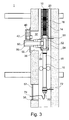
- only one opening must be provided in the exhaust duct 30 for mounting. In existing old fireplaces, which are used as exhaust duct 30, this only one opening per apartment in the old fireplace 34 must be introduced.
- the lowermost chimney tee 52 is connected downwardly to a cuff lid 80 which closes the combustion air tube tee 54 downwardly but at the same time provides a passageway for the chimney pipe 10.
- a condensate drain 70 at the lower end of the chimney pipe 18.
- From this condensate drain 70 from the condensate is introduced via a condensate line 72 either in a neutralization box for neutralization or directly into the sewer.
- the condensate drain 70 is fastened by means of a holder 72 to the exhaust air duct 30 and thus carries the load of the section 18 of the chimney pipe 10 arranged above it.
- the connection elements 50 are fastened to the chimney block 34 in a similar manner via holders 51.
- the chimney tee 52 is suitably held in a combustion air tube tee 54. This results in a good attachment of the chimney system 1, wherein occurring thermal stresses are compensated by the flexible design of the chimney pipe 10 and the combustion air pipe 20.
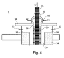
- the mouth of the fireplace system above the roof comprises a Kaminabdeckplatte 94, which is placed on an existing fireplace or on the chimneys 34 of the exhaust duct 30 and fixed there. Laterally openings 96 are provided in the exhaust duct 30 below the Kaminabdeckplatte, can be discharged through the room air 32 to the outside.
- the combustion air tube 20 is connected to a tubular passage 98 in the Kaminabdeckplatte 94, on which a chimney closure sleeve 90 is placed.
- the chimney pipe 10 penetrates the chimney cowling 90 and is fastened by it. At the same time, the chimney closure sleeve 90 prevents rainwater from entering the combustion air tube 20.
- a chimney system 1 in an existing chimney of chimney blocks 34 will now be described by way of example.
- the existing chimney 34 which later forms the exhaust air duct 30, pried on all floors to receive mounting and passage openings 36.
- the attachment points are fixed in all floors and the T-shaped connection elements 50 are fastened by means of holders 51 within the exhaust duct 30 on the chimney block 34.
- a hole is drilled in the chimney 34, a suitable expansion dowel inserted into the hole and the holder 51 is screwed with a fastened thereto screw in the expansion dowel.
- the condensate drain 70 is fixed in the basement of the building within the exhaust duct 30 with a holder 72 on the fireplace block 34.
- a chimney pipe section 18 is introduced into the exhaust air duct 30 and connected to the condensate drain 70 and with a cuff cover 80 which seals the lowermost connecting element 50 down.
- a section 14 of the chimney pipe 10 is connected to the lower connection of a chimney pipe tee 52 of the connection element 50 and secured by means of a securing ring. Then, the spacers 16 are fixed to the chimney pipe 10. Subsequently, a portion of a combustion air tube 20 is slid over the chimney pipe 10 and connected and secured to the lower port of the combustion air pipe tee 54. Thereafter, the flexible combustion air pipe 20 is extended to the length of the chimney pipe 10.
- connection element 50 The assembly of the connecting element 50 with the pipe sections 10, 20 attached thereto is then introduced down into the exhaust air duct 30. Subsequently, the connection element 50 is fastened by means of holders 51 in the exhaust duct 30 to the chimney block 34. One floor below, the variable-length combustion air pipe is then pushed together and then the chimney pipe 10 arranged therein is connected to the upper connection of the chimney pipe T-piece 52 of the connection element 50 of the lower floor. Below is the Combustion air pipe 20 pulled apart to also connect to the connection member 50 by being connected to the upper terminal of the combustion air pipe T-piece 54 of the lower floor.
- the tubular connection piece 98 in the chimney cover plate 94 is connected to a section of the combustion air tube 20.
- a piece of the chimney pipe 10 is provided with spacers and inserted through the Kaminabdeckplatte in the combustion air pipe 20. Now the combustion air pipe 20 is extended to the length of the chimney pipe 10. Thereafter, the chimney pipe 10 is secured to the Kaminabdeckplatte 94 by means of the Kaminab gleichmuffe 90. Now the Kaminabdeckplatte 94 is inserted with the attached into one another stuck tubes 10, 20 from above into the exhaust duct 30 and secured to the upper mouth of the exhaust duct 30.
- the combustion air tube 20 is pushed together to connect the chimney pipe 10 with the upper port of a chimney pipe tee 54. Once this is done, the combustion air tube 20 is pulled apart again and connected to the upper port of the combustion air tube tee 54 and secured.
- a chimney introduction pipe 60 is attached to each side port of the chimney pipe tees 52.
- a combustion air inlet tube 90 is plugged onto each side port of the combustion air tube tees 54.
- a wall panel 56 is mounted with a sealed passage for the combustion air connection pipe 90 on the openings 36.
- the exhaust fan 40 is with the Exhaust filter 42 attached, which consumed room air 32 blows through the wall panel 56 into the exhaust duct 30 into it.
- the opening 36 is closed in the condensate drain 70 with a door 57 through which a condensate line 74 is passed airtight.
Landscapes
- Engineering & Computer Science (AREA)
- Mechanical Engineering (AREA)
- General Engineering & Computer Science (AREA)
- Chemical & Material Sciences (AREA)
- Combustion & Propulsion (AREA)
- Architecture (AREA)
- Chimneys And Flues (AREA)
- Air Supply (AREA)
Abstract
Description
- Die Erfindung betrifft ein Kaminsystem für Feuerungsanlagen, insbesondere für gas- oder ölbeheizte Heizungsanlagen. Das Kaminsystem dient der Abfuhr von Verbrennungsgasen, der Zufuhr von Verbrennungsluft sowie zur Abfuhr von verbrauchter Raumluft. Ein derartiges Kaminsystem kann auch als Luft-Abgas-Abluft-System bezeichnet werden.
- Gebäude werden meistens durch Verbrennung von Kohlenwasserstoffen wie Erdöl, Erdgas oder Kohle geheizt. Das dabei entstehende Kohlendioxid ist mitverantwortlich für den Treibhauseffekt. Das Zurückhalten des Kohlendioxids würde aber einen derart großen Energieaufwand erfordern, dass es sich von der Energiebilanz her nicht mehr lohnte, die Kohlenwasserstoffe zu verbrennen. Um die Luftverschmutzung möglichst niedrig zu halten und unsere Ressourcen an fossilen Brennstoffen zu schonen, ist es wichtig, den Verbrauch an Brennmaterial zu reduzieren.
- Da die Kohlenwasserstoffe aus lebender Substanz entstanden, enthalten sie eine große Menge an Kohlenstoff und in geringeren Mengen eine Vielzahl weiterer Stoffe, wie zum Beispiel Schwefel und Stickstoff.
- Diese Stoffe gelangen bei der Verbrennung von Kohlenwasserstoffen in das Verbrennungsgas. Das Verbrennungsgas enthält daher neben Wasserdampf, Kohlendioxid, Russ, Schwefeloxiden und Stickoxiden auch Schwefelsäure. Die Stickstoffoxide entstehen größtenteils aus Stickstoff, welcher ebenfalls aus der Verbrennungsluft stammt.
- Im Gegensatz zum Kohlendioxid und zu den Stickoxiden können Wasserdampf, Russ, Schwefeloxide und Schwefelsäure mit geeigneten Mitteln aber hohem technischen und energetischen Aufwand zumindest teilweise zurückgehalten werden.
- Herkömmliche Kamine sind entweder aus Schamotte gemauert oder bestehen aus Edelstahl. Diese Materialien sind nicht genügend korrosionsfest und versotten, wenn das Verbrennungsgas darin kondensieren würde, d.h. wenn sie über längere Zeit einem flüssigen, sauren Kondensat mit pH-Werten von 1,5 - 3,7 ausgesetzt sind.
- Die Temperaturen in solchen herkömmlichen Kaminen dürfen daher nicht unter den Taupunkt des Verbrennungsgases fallen, um eine Kondensation des Verbrennungsgases zu verhindern. Bei herkömmlichen Kaminen wird daher die Temperatur des Verbrennungsgases am Kessel so eingestellt, dass es im Kamin zu keiner Kondensation und daher keiner Versottung kommt.
- Dies hat zur Folge, dass die Verbrennungsgase vollständig in die Atmosphäre geleitet werden, was eine hohe Verschmutzung der Atmosphäre sowie ein hoher Energieverlust bedeutet.
- Seit einiger Zeit werden daher Kamine aus hochwertigen Kunststoffen wie PVDF (Polyvinylidenfluorid) eingesetzt, welche der Einwirkung des Kondensats standzuhalten vermögen. Hier wird eine Kondensation der Verbrennungsgase bewusst zugelassen und dabei ein großer Teil der Energie, welche im Verbrennungsgas gebunden ist, zurück gewonnen. Man spricht daher auch von sog. Kondensationskaminen. Zusätzlich kann ein großer Teil der im Rauchgas enthaltenen, umweltbelastenden Stoffe wie beispielsweise Schwefelsäure, unverbrannte Kohlenwasserstoffe, Wasserdampf und Russ im Kaminrohr zurückgehalten werden.
- Die Energieeinsparung, die sich durch einen geringeren Bedarf an Brennstoff zeigt, dieser Technik beruht auf verschiedenen Faktoren. Zunächst kann bei Kondensationskaminen die Heizkesselabgastemperatur auf ein Minimum abgesenkt werden. Bei der sog. Brennwert-Technik kann die Temperatur des Abgases beim Austritt aus dem Heizkessel nur etwa 30-40 °C und bei der Niedertemperatur-Technik etwa 90-140 °C betragen. Eine Absenkung der Rauchgastemperatur bedeutet eine effizientere Nutzung der Verbrennungswärme zum Aufheizen des Wärmeträgers (meist Wasser) und eine Einsparung an teurem Brennstoff. Kondensationskamine erlauben dabei erstmals die Heizkessel mit der vom Hersteller vorgegebene Mindestkesselwassertemperatur zu betreiben, aus der dann die tiefstmöglichste Abgastemperatur und daraus wieder der höchstmögliche Wirkungsgrad der Feuerungsanlage resultiert. Zudem erlaub diese Technik erheblich verlängerte Brennerlaufzeiten wobei Anfahr- und Abstellverluste (z.B. Faktor 10) der Anlage vermieden werden und Materialstress minimiert wird.
- Zusätzlich findet eine weitere Abkühlung des Rauchgases im Kondensationskamin statt, welches bei dieser Technik nicht wärmeisoliert ist und von einströmender frischer Verbrennungsluft umströmt wird. Dabei wird die am Kaminrohr des Kondensationskamins entlang strömende frische und Umgebungstemperatur-kalte Verbrennungsluft vorgewärmt. Durch die Abkühlung der Verbrennungsgase gelangt ein großer Teil derselben zur Kondensation, wobei die Kondensationswärme wiederum an die frische Verbrennungsluft abgegeben wird.
- Die derart vorgewärmte frische Verbrennungsluft wird dann zum Betrieb des Heizkessels verwendet und somit die Wärme der Verbrennungsgase wiederverwendet.
- Im Kamin entsteht bei der Kondensation der Verbrennungsgase ein flüssiges, je nach Brennstoff stark säurehaltiges Kondensat, welches den Kaminwänden entlang nach unten fließt. Am Fuß des Kaminrohrs wird das Kondensat gefangen und in einen Neutralisationsbehälter geleitet, der die Schadstoffe bindet und neutralisiert. Dieser Neutralisationsbehälter enthält üblicherweise einem Aktivkohlefilter sowie ein Neutralisationsgranulat, welches die Säuren des Kondensats neutralisiert. Als Neutralisationsgranulat wird entweder chemisch hergestelltes Kalziumkarbonat oder natürlicher Kalk verwendet. Nach der Neutralisation entsteht aus dem Kondensat reines unbedenkliches Wasser, das in die Kanalisation geleitet wird. Beispielsweise entsteht so aus einem Liter verbranntem Öl 0,8 Liter Kondensat, das nicht als Abgas in die Umwelt abgegeben wird.
- Die
DE 3 421 112 Al beschreibt einen Kondensationskamin, welcher für die Anwendung der Technik des kalten, nassen, kondensierenden Kamins eingesetzt wird. Dieser Kamin entfaltet seinen größten Wirkungsgrad hinsichtlich Wärmerückgewinnung und Verbrennungsgasreinigung bei Heizungssystemen für kleinere Gebäude. Ein derartiges Kaminsystem ist aus einzelnen miteinander verschweißten Kunststoffrohren und ist lediglich für eine Feuerstelle geeignet. - Ein großes Energieeinsparpotential ist auch bei mehrstöckigen Gebäuden mit Etagenheizung gegeben, bei denen mehrere Heizkessel oder Heizgeräte in Form einer Kaskade an einen gemeinsamen Kamin angeschlossen sind, welche, um eine Versottung des Kamins zu vermeiden, bei sehr hohen Abgastemperaturen betrieben werden müssen.
- Die Erfindung stellt sich daher die Aufgabe ein Kondensationskaminsystem insbesondere für mehrstöckige Gebäude mit Etagenheizung bereitzustellen, das Wärmeenergie zurückgewinnt und den Installations- und Investitionsaufwand eines derartigen Kondensationskaminsystems wesentlich verbessert.
- Weiterhin besteht insbesondere bei gedämmten und mit neuen Fenstern versehenen Gebäuden der Bedarf, die Wohnräume zu be- und entlüften, da diese aus energetischen Gründen möglichst luftdicht ausgeführt werden. Bei einfachen Lüftungsanlagen wird dies häufig dadurch gelöst, dass die Abluft zentral abgesaugt wird und die Zuluft dezentral über geeignete Öffnungen in den Außenwänden oder an den Fenstern kontrolliert nachströmen kann. Für die zentrale Absaugung muss ein hoher baulicher Verrohungsaufwand betrieben werden, so dass derartige Systeme bei Renovierungen häufig nicht verwendet werden, was zu einem schlechten und meist zu feuchten Raumklima führt. Die Erfindung stellt sich die Aufgabe, auch das Problem der Be- und Entlüftung von Gebäuden zu lösen.
- Die oben genannten Probleme stellen sich insbesondere bei der energetischen Sanierung mehrgeschossiger Wohnhäuser, wobei das Gebäude gedämmt wird, neue Fenster sowie eine neue Heizung mit Brennwerttechnologie eingebaut werden. Bei derartigen Sanierungen muss eine kontrollierte Be- und Entlüftung eingebaut werden sowie eine Kaminsanierung durchgeführt werden und eine raumluftunabhängige Verbrennungsluftzuführung bereitgestellt werden.
- Die oben genannten Aufgaben werden erfindungsgemäß durch den Gegenstand der unabhängigen Patentansprüche gelöst. Vorteilhafte Weiterbildungen der Erfindung sind Gegenstand der abhängigen Ansprüche.
- Insbesondere wird das oben genannte Problem durch ein Kaminsystem gelöst, welches ein Kaminrohr zur Abfuhr von Verbrennungsgasen, ein Verbrennungsluftrohr zur Zufuhr von Verbrennungsluft und einen Abluftkanal zur Abfuhr von Raumluft aufweist, wobei das Kaminrohr innerhalb des Verbrennungsluftrohrs angeordnet ist und das Verbrennungsluftrohr innerhalb des Abluftkanals angeordnet ist. Mit einem solchen Kaminsystem wird zum einen eine ordnungsgemäße Abfuhr der Verbrennungsgase durch das Kaminrohr gewährleistet, wobei durch die Anordnung des Kaminrohrs in einem Verbrennungsluftrohr die Verbrennungsluft durch die heißen Verbrennungsgase vorgeheizt werden und somit die Wärmeenergie in den Rauchgasen wiederverwendet wird. Zum anderen kann in dem Kaminsystem in einem Abluftkanal verbrauchte Raumluft aus dem Gebäude abgeführt werden, wobei auch hier die Verbrennungsluft, die die Heizung zugeführt wird, durch die warme verbrauchte Raumluft vorgewärmt wird. Damit wird auch die Wärmeenergie, die in der verbrauchten Raumluft steckt, über die Verbrennungsluft zum Teil wiedergewonnen.
- Durch das Kaminsystem werden daher auf energetisch vorteilhafte Weise drei verschiedene Funktionen durchgeführt, nämlich erstens die Abfuhr der Verbrennungsgase aus dem entsprechenden Heizkessel, zweitens eine geregelte Zufuhr von Verbrennungsluft zum Heizkessel, wie sie für eine raumluftunabhängige Betriebsweise des Heizkessels notwendig ist, und drittens eine geregelte Abfuhr von verbrauchter Raumluft über einen Abluftkanal, in dem Verbrennungsluftrohr und Kaminrohr angeordnet sind. Zur Gewährleistung dieser drei Funktionen muss daher lediglich eine entsprechende Kaminsanierung durchgeführt werden und es müssen keine weiteren Zuluft- oder Abluftkanäle in dem Gebäude verlegt werden. Dadurch verringert sich der Installationsaufwand erheblich, was insbesondere bei Renovierungen von Mehrfamilienhäusern sehr vorteilhaft ist. Üblicherweise kann der dort schon vorhandene Kamin als Abluftkanal zur Abfuhr der Raumluft verwendet werden.
- In einer bevorzugten Ausführungsform ist das Kaminsystem als ein Gegenstrom-Wärmetauscher ausgebildet, wobei die warmen Verbrennungsgase durch das Kaminrohr hindurch Wärme an die kalte Verbrennungsluft übertragen und diese auf heizen und wobei zudem die warme Raumluft durch das Verbrennungsluftrohr hindurch Wärme an die kalte Verbrennungsluft überträgt. Durch diese beiderseitige Wärmeübertragung, zum einen durch die warmen Verbrennungsgase und zum anderen durch die warme verbrauchte Raumluft auf die kalte Verbrennungsluft, wird ein Großteil der ansonsten verlorengehenden Wärmeenergie zurückgewonnen. Das Kaminsystem trägt daher erheblich zur Energieeinsparung bei.
- Bevorzugt ist das Kaminrohr aus einem säurebeständigen Kunststoffmaterial, bevorzugt aus PVDF, hergestellt. Durch ein säurebeständiges Kunststoffmaterial, bevorzugt PVDF, kann das Kaminrohr problemlos mit niedrigen Abgastemperaturen betrieben werden, sodass der Heizkessel im Brennwertbetrieb betrieben werden kann. Vorteilhafterweise kondensiert das warme Rauchgas im Kaminrohr und das Kondensat läuft innerhalb des Kaminrohrs nach unten ab. Durch die Kondensation kann daher weitere Wärme zurückgewonnen werden.
- Bevorzugt weist das Kaminrohr Abschnitte aus flexiblem Rohr auf. Ein flexibles Kaminrohr kann Längen- und Lageungenauigkeiten ausgleichen, was insbesondere bei der Sanierung von bestehenden älteren Kaminen Vorteile mit sich bringt. Weiterhin ist die Wärmeübertragung von den heißen Rauchgasen auf die kühle Verbrennungsluft durch die vergrößerte Oberfläche derartiger flexibler Rohre besonders effektiv.
- Bevorzugt ist das Kaminrohr mittels Abstandshaltern im Verbrennungsluftrohr angeordnet. Zur Zentrierung des Kaminrohrs im Verbrennungsluftrohr werden Abstandshalter verwendet, die am Kaminrohr befestigt sind.
- Bevorzugt weist das Verbrennungsluftrohr Abschnitte aus einem längenveränderlichen Rohr auf, bevorzugt aus einem längenveränderlichen, flexiblen Aluminiumrohr. Indem das Verbrennungsluftrohr Abschnitte aus einem längenveränderlichen Rohr, insbesondere einem Aluminiumflexrohr aufweist, gestaltet sich die Montage des Kaminsystems besonders einfach. Zur Montage des Kaminsystems kann nämlich dann das Verbrennungsluftrohr zusammengeschoben werden, um das darin angeordnete Kaminrohr problemlos zu montieren.
- Weiterhin stellt ein flexibles längenveränderliches Rohr eine größere Oberfläche bereit, als ein entsprechendes glattes starres Rohr, sodass der Wärmeübergang von der warmen Raumluft auf die kalte Verbrennungsluft besonders effektiv erfolgt. Daneben gleicht ein längenveränderliches, flexibles Aluminiumrohr Montageungenauigkeiten, insbesondere bei der Sanierung von bestehenden Kaminen aus. Bevorzugt ist der Abluftkanal durch Kaminsteine aus einem mineralischen Werkstoff gebildet. Alte, zu sanierende Kamine bestehen üblicherweise ebenfalls aus Kaminsteinen aus einem mineralischen Werkstoff und können nach einer Grundreinigung direkt als Abluftkanal dienen.
- Bevorzugt weist das Kaminsystem einen einzigen Kondensatablauf für das gesamte Kaminsystem auf, wobei der Kondensatablauf an das untere Ende des Kaminrohrs angeschlossen ist. Bevorzugt wird über das Kaminrohr anfallendes Kondensat aus dem Kaminrohr selbst, sowie aus den daran angeschlossenen Heizungsanlagen abgeführt. Damit entfallen separate Kondensatleitungen, separate trockenfallende Syphons und individuelle Einleitungen in das Abwassersystem. Das Kondensat wird zentral an einem Kondensatablauf am unteren Ende des Kaminrohrs aufgefangen und gegebenenfalls über eine Neutralisationsbox in das Abwassersystem eingeleitet.
- Bevorzugt weist das Kaminsystem weiterhin einen Abluftventilator auf, welcher Raumluft in den Abluftkanal einbläst. Bevorzugt ist ein Abluftventilator pro Wohnung vorgesehen. Der Abluftventilator bestimmt die in der Wohnung oder im Gebäude auszutauschende Luftmenge, indem er verbrauchte Raumluft in den Abluftkanal einbläst, sodass an dezentralen Einströmöffnungen an der Gebäudehülle Frischluft in das Gebäude nachströmen kann. Das Kaminsystem übernimmt somit die Funktion einer zentralen Abluftanlage. Um Verschmutzungen des Abluftkanals zu verhindern, ist vor dem jeweiligen Abluftventilator ein Abluftfilter angeordnet, der Stäube, Fetttröpfchen und andere Verschmutzungen in der Raumluft wirksam herausfiltert. Der Abluftfilter kann eine Filtermatte umfassen, die in regelmäßigen Abständen gewechselt werden muss.
- Bevorzugt weist das Kaminsystem weiterhin ein Anschlusselement zum Anschluss eines Heizgeräts an das Kaminsystem auf, wobei das Anschlusselement ein Kaminrohr-T-Stück, welches an das Kaminrohr angeschlossen ist, aufweist und ein Verbrennungsluftrohr-T-Stück, welches an das Verbrennungsluftrohr angeschlossen ist, wobei das Verbrennungsluftrohr-T-Stück das Kaminrohr-T-Stück umgibt. Mithilfe eines solchen Anschlusselements, das aus zwei T-Stücken besteht, wobei das Kaminrohr-T-Stück innerhalb des Verbrennungsluftrohr-T-Stücks angeordnet ist, kann das Kaminrohr sowie das Verbrennungsluftrohr an die entsprechenden Heizkessel auf den jeweiligen Stockwerken eines Gebäudes angeschlossen werden. Dieses Doppel-T-Stück wird bevorzugt mittels eines speziellen Halters im Kaminstein sicher befestigt, besonders bevorzugt mittels eines Spreizdübels. Hierbei ist sowohl ein gasdichter Anschluss des Kaminrohrs für die Abgase des Heizkessels, als auch ein gasdichter Anschluss des Verbrennungsluftrohrs an den Heizkessel gegeben. Somit können innerhalb des Kaminsystems problemlos drei Medien völlig unabhängig voneinander transportiert werden, nämlich Verbrennungsgase, Verbrennungsluft und Abluft aus dem Gebäude.
- Bevorzugt ist das unterste Verbrennungsluftrohr-T-Stück und das unterste Kaminrohr-T-Stück mit einem Stulpdeckel verbunden, der das Verbrennungsluftrohr-T-Stück nach unten verschließt und einen Durchgang für das Kaminrohr bereitstellt. Der Stulpdeckel bildet einen Abschluss für die Verbrennungsluft nach dem untersten Anschlussstück am Kaminsystem. Er ermöglicht den Durchgang des Kaminrohrs, sodass anfallendes Kondensat nach unten zu dem einzigen Kondensatablauf geleitet werden kann.
- Bevorzugt weist das Kaminsystem weiterhin eine Kamineinführung auf, welche an einem seitlichen Anschluss des Kaminrohr-T-Stücks angeschlossen ist und bevorzugt zum Kaminrohr hin fallend angeordnet ist, sowie ein Verbrennungsluftanschlussrohr, welches an einen seitlichen Anschluss des Verbrennungsluftrohr-T-Stücks angeschlossen ist und welches die rohrförmige Kamineinführung umgibt. Über eine fallende Kamineinführung kann zusätzlich zu den Rauchgasen, die über dieses Rohr in das Kaminrohr eingeleitet werden, auch Kondensat aus dem Heizgerät in das Kaminrohr abfließen. Über das Verbrennungsluftanschlussrohr wird ein daran angeschlossener Heizkessel mit der notwendigen Verbrennungsluft versorgt, so dass er raumluftunabhängig betrieben wird.
- Bevorzugt ermöglicht das Kaminsystem eine Mehrfachbelegung und weist mehrere Abluftventilatoren und/oder mehrere Anschlusselemente auf. Das Kaminsystem kann insbesondere im Geschosswohnungsbau verwendet werden, wobei in einem Haus mit mehreren Etagen jede Etage ihre eigene Heizung bzw. ihren eigenen Heizkessel aufweist, welche an ein gemeinsames Kaminsystem angeschlossen sind. Weiterhin können die einzelnen Wohnungen über das gemeinsame Kaminsystem zentral entlüftet werden.
- Bevorzugt weist das Kaminsystem weiterhin eine Wandblende auf, die einen abgedichteten Durchgang für das Verbrennungsluftanschlussrohr und gleichzeitig einen luftdichten Anschluss des Abluftventilators an den Abluftkanal bereitstellt. Der gesamte Anschluss eines Heizgeräts sowie der Anschluss des Ventilators an den Abluftkanal erfolgt über eine gemeinsame Wandblende, was die Montage dieser Komponenten erheblich vereinfacht.
- Die oben genannten Aufgaben werden ebenfalls gelöst durch ein Verfahren zur Montage eines Kaminsystems, aufweisend ein Kaminrohr zur Abfuhr von Verbrennungsgasen, ein Verbrennungsluftrohr mit Abschnitten aus einem längenveränderlichen Rohr zur Zufuhr von Verbrennungsluft und einen Abluftkanal zur Abfuhr von Raumluft, wobei das Verfahren die folgenden Schritte aufweist:
- a. Anordnen des Kaminrohrs innerhalb des Verbrennungsluftrohrs,
- b. Anordnen des Verbrennungsluftrohrs mit dem darin angeordneten Kaminrohr innerhalb des Abluftkanals,
- c. Zusammenschieben des Verbrennungsluftrohrs, um das Kaminrohr mit weiteren Elementen zu verbinden, danach
- d. Auseinanderziehen des Verbrennungsluftrohrs, um das Verbrennungsluftrohr mit weiteren Elementen zu verbinden.
- Durch diese Montageschritte kann sowohl das Verbrennungsluftrohr, als auch das darin angeordnete Kaminrohr innerhalb des Abluftkanals sicher und einfach montiert werden. Durch das längenveränderliche Rohr für die Verbrennungsluftzufiihrung wird nach dem Zusammenschieben Montageraum geschaffen, sodass der Monteur das darin angeordnete Kaminrohr sauber an weitere Elemente, wie beispielsweise ein Kaminrohr-T-Stück, einen Stulpdeckel oder an eine Muffe, anschließen kann. Dies ist insbesondere deshalb wichtig, da das Kaminrohr sowie das Verbrennungsluftrohr mindestens ein Mal pro Etage mittels den Doppel-T-Stücken an den Kaminsteinen befestigt wird.
- Weitere bevorzugte Ausführungsformen der Erfindung ergeben sich aus den Unteransprüchen.
- Im Folgenden werden bevorzugte Ausführungsbeispiele der Erfindung mit Hilfe der Zeichnung beschrieben. In denen zeigt:
- Fig. 1:
- einen schematischen Längsschnitt durch ein erfindungsgemäßes Kaminsystem;
- Fig. 2:
- einen schematischen Längsschnitt eines Details der Anschlussstelle des Kaminsystems gemäß
Fig. 1 ; - Fig. 3:
- einen schematischen Längsschnitt eines Details des unteren Abschlusses des Kaminsystems gemäß
Fig. 1 ; und - Fig. 4:
- einen schematischen Längsschnitt eines Details der Mündung des Kaminsystems gemäß
Fig. 1 . - Im Folgenden werden mit Bezug auf die Figuren bevorzugte Ausführungsformen der Erfindung beschrieben.
-
Figur 1 zeigt eine Gesamtansicht eines Kaminsystems 1, aufweisend ein Kaminrohr 10 zur Abfuhr von Verbrennungsgasen 12, ein Verbrennungsluftrohr 20 zur Zufuhr von Verbrennungsluft 22 zu den Heizgeräten (nicht dargestellt) und einen Abluftkanal 30 zur Abfuhr von Raumluft 32. DieFiguren 2 - 4 zeigen Details des Kaminsystems 1. - Wie dargestellt, befindet sich innerhalb des Abluftkanals 30 das Verbrennungsluftrohr 20. Innerhalb des Verbrennungsluftrohrs 20 ist das Kaminrohr 10 angeordnet. Damit können durch das Kaminsystem 1, drei verschiedene Medien transportiert werden, nämlich Verbrennungsgase 12 aus den Heizkesseln, welche durch das Kaminrohr 10 nach oben, in der Regel über das Dach, in die Umgebung abgeführt werden. Zum Anderen wird die zur Verbrennung des Brennstoffs benötigte Verbrennungsluft 22 über das Verbrennungsluftrohr 20 den einzelnen Heizkesseln raumluftunabhängig zugeführt. Schließlich dient das Kaminsystem 1 auch zur Abfuhr von verbrauchter Raumluft 32, welche mittels Abluftventilatoren 40 aus dem Raum angesaugt und über den Abluftkanal 30 nach oben aus dem Gebäude heraus abgeführt wird. Wie dargestellt, tritt die Raumluft 32 am oberen Ende des Kaminsystems 1 seitlich aus dem Abluftkanal 30 aus. Die Verbrennungsluft 32 wird über seitliche Öffnungen 92 in einer Kaminabschlussmuffe 90 in dem Ringspalt zwischen Verbrennungsluftrohr 20 und Kaminrohr 10 angesaugt. Die Verbrennungsgase 12 werden aus dem Kaminrohr 10 abgeführt, das sich durch die Kaminabschlussmuffe 90 hindurch erstreckt..
- Der Abluftkanal 30 besteht bevorzugt aus mineralischen Kaminsteinen 34, die auch aus einem bereits in einem Gebäude existierenden Kamin bestehen können. In diesen bestehenden Kamin 34 wird dann ein Verbrennungsluftrohr 20 mit einem darin angeordneten Kaminrohr 10 eingezogen. Als Abluftkanal 30 dient dann der verbleibende Raum zwischen den Kaminsteinen 34 und dem Verbrennungsluftrohr 20. Die Verbrennungsluft 22 wird im Ringspalt zwischen Verbrennungsluftrohr 20 und Kaminrohr 10 angesaugt.
- Mit einer derartigen Anordnung funktioniert das Kaminsystem 1 als ein Gegenstromwärmetauscher, wobei die warmen Verbrennungsgase 12 durch das Kaminrohr 10 hindurch Wärme an die kalte Verbrennungsluft 22 übertragen, welche im Ringspalt zwischen Kaminrohr 10 und Verbrennungsluftrohr 20 nach unten zu den einzelnen Heizkesseln (nicht dargestellt) strömt. Damit wird die Verbrennungsluft 22 durch die Wärme der Verbrennungsgase 12 aufgeheizt und somit wird deren Wärme wiedergewonnen. Gleichzeitig wird die verbrauchte, in der Regel warme Raumluft 32 durch den Abluftkanal 30 nach oben aus dem Gebäude bzw. den einzelnen Wohnungen gefördert und streicht dabei außen an dem Verbrennungsluftrohr 20 vorbei. Dadurch gibt die warme Raumluft 32 ebenfalls Wärme an die Verbrennungsluft 22 ab. Somit wird auch die Wärme der warmen Raumluft 32 zu einem großen Teil wiedergewonnen.
- Wie in
Figur 1 dargestellt, ist das Kaminsystem 1 für eine Mehrfachbelegung ausgelegt, das heißt an das Kaminsystem 1 können mehrere Heizungen bzw. Heizkessel angeschlossen werden. Insbesondere eignet es sich daher für Sanierungen im Geschosswohnungsbau, wobei ein bestehender gemauerter Kamin 34 zu einem erfindungsgemäßen Kaminsystem 1 umgebaut werden kann und dann in jedem Geschoss des Gebäudes ein Heizkessel an das Kaminsystem 1 angeschlossen werden kann. Weiterhin dient das Kaminsystem 1 zur individuellen Entlüftung jedes daran angeschlossenen Geschosses bzw. jeder daran angeschlossenen Wohnung und sorgt somit für ein angenehmes Raumklima. - Dementsprechend können die Bewohner der einzelnen Geschosse ihre Heizgewohnheiten individuell regeln und auch ihre Lüftungsgewohnheiten individuell wählen.
- Das Kaminrohr 10 besteht bevorzugt aus einem säurenbeständigen Kunststoffmaterial, bevorzugt aus Polyvinylidenfluorid (PVDF). Wie in den
Figuren 1 - 4 dargestellt, weist das Kaminrohr 10 Abschnitte aus einem flexiblen Rohr 14 auf. Abstandshalter 16 außen an dem Kaminrohr 10 stellen sicher, dass das Kaminrohr 10 im Wesentlichen zentrisch innerhalb des Verbrennungsluftrohrs 20 angeordnet ist. - Das Verbrennungsluftrohr 20 besteht bevorzugt aus einem längenveränderlichen Rohr, bevorzugt aus einem längenveränderlichen flexiblen Aluminiumrohr 20. Derartige Rohre sind auch unter dem Begriff "Aluminumflexrohr" bekannt und werden in der Lüftungstechnik verwendet. Sie zeichnen sich dadurch aus, dass sie flexibel verlegt werden können und ihre Länge um bevorzugt 100 % verändert werden kann. Derartige flexible Aluminiumrohre können auseinander gezogen im Vergleich zum zusammen geschobenen Zustand die doppelte Länge erreichen.
- Wie in
Figur 2 im Detail dargestellt, erfolgt der Anschluss von Heizkesseln an das Kaminrohrsystem 1 über Anschlusselemente 50, welche jeweils ein Kaminrohr-T-Stück 52 und ein Verbrennungsluftrohr-T-Stück 54 aufweisen. Dabei umgibt das Verbrennungsluftrohr-T-Stück 54 das Kaminrohr-T-Stück 52 und ist in diesem befestigt. Das Kaminrohr-T-Stück 52 ist an zwei Teile eines Kaminrohrs 10 angeschlossen und sorgt dafür, dass, von der Seite aus, Verbrennungsgase 12 in das Kaminrohr 10 eingeleitet werden können. Zu diesem Zweck ist eine rohrförmige Kamineinführung 60 an einen seitlichen Anschluss des Kaminrohr-T-Stücks 52 angeschlossen. Bevorzugt ist die Kamineinführung 60 zum Kaminrohr-T-Stück 52 hin leicht fallend angeordnet, damit Kondensat, welches gegebenenfalls im Heizkessel anfällt, direkt in das Kaminrohr 10 abfließen kann, was auch den gemeinsamen Syphon am Kondensatablauf 70 sicherer füllt und ein Trockenfallen desselben verhindert. - Das Verbrennungsluftrohr-T-Stück 54 ist zwischen zwei Teilen des Verbrennungsluftrohrs 20 geschaltet und stellt einen seitlichen Anschluss für Verbrennungsluft 22 bereit. Zu diesem Zweck ist an den seitlichen Anschluss des Verbrennungsluftrohr-T-Stücks 54 ein Verbrennungsluftanschlussrohr 90 angeschlossen, welches die Kamineinführung 60 umgibt. Über den Ringspalt zwischen Verbrennungsluftanschlussrohr 90 und Kamineinführung 60 wird die zur Verbrennung des Brennstoffs in einem Heizgerät benötigte Verbrennungsluft 22 dem Heizkessel (nicht dargestellt) zugeführt.
- Um verbrauchte Raumluft 32 aus dem entsprechenden Gebäude oder der Wohnung abzuführen, wird diese mittels eines elektrischen Abluftventilators 40 in den Abluftkanal 30 eingeblasen. Die Fördermenge des Abluftventilators 40 ist bevorzugt regelbar, sodass der Luftaustausch in dem Gebäude bzw. in der entsprechenden Wohnung individuell eingestellt werden kann. Um Verschmutzungen des Abluftventilators 40 und des Abluftkanals 30 zu verhindern ist vor den Abluftventilator 40 ein Abluftfilter 42 geschaltet. Der Abluftfilter 42 verhindert ein Eindringen von Staub, Fetttröpfchen oder anderen Verschmutzungen in den Abluftkanal 30. Bevorzugt wird als Abluftfilter eine Filtermatte der Filterklasse F4 verwendet, die je nach Verschmutzung halbjährlich ausgetauscht werden sollte.
- Der Abluftventilator 40 ist an einer Wandblende 56 befestigt, die eine Öffnung in dem Kaminschacht 30 abdichtet. Bevorzugt wird das Verbrennungsluftanschlussrohr 90 und die Kamineinführung 60 ebenfalls durch diese Wandblende geführt, sodass für den Anschluss der Heizung einer Wohnung an das Kaminsystem 1 lediglich eine Anschlussstelle vorgesehen werden muss. Damit vereinfachen sich die Montagevorgänge für den Anschluss eines Heizkessels an das Kaminsystem 1. Insbesondere eignet sich eine große Öffnung im Abluftschacht 30 dazu, das Kaminsystem 1, insbesondere die Anschlusselemente innerhalb des Abluftschachts 30, zu montieren. Somit muss im Abluftschacht 30 für die Montage lediglich eine Öffnung vorgesehen werden. Bei bestehenden alten Kaminen, welche als Abluftschacht 30 verwendet werden, muss hierbei lediglich eine Öffnung pro Wohnung in den alten Kamin 34 eingebracht werden.
- Das unterste Kaminrohr-T-Stück 52 ist nach unten mit einem Stulpdeckel 80 verbunden, der das Verbrennungsluftrohr-T-Stück 54 nach unten verschließt, aber gleichzeitig einen Durchgang für das Kaminrohr 10 bereitstellt. Durch dieses nach unten verlaufende Kaminrohrstück 18 kann im Kaminrohr anfallendes Kondensat und auch Kondensat aus den angeschlossenen Heizgeräten gemeinsam in einen Kondensatablauf 70 am unteren Ende des Kaminrohrs 18 einlaufen. Von diesem Kondensatablauf 70 aus wird das Kondensat über eine Kondensatleitung 72 entweder in eine Neutralisationsbox zur Neutralisation oder direkt in die Kanalisation eingeleitet.
- Der Kondensatablauf 70 ist mittels eines Halters 72 am Abluftkanal 30 befestigt und trägt somit die Last des darüber angeordneten Abschnitts 18 des Kaminrohrs 10. Auf ähnliche Weise sind die Anschlusselemente 50 über Halter 51 am Kaminstein 34 befestigt. Das Kaminrohr-T-Stück 52 ist geeignet in einem Verbrennungsluftrohr-T-Stück 54 gehalten. Damit ergibt sich eine gute Befestigung des Kaminsystems 1, wobei auftretende Wärmespannungen durch die flexible Ausgestaltung des Kaminrohrs 10 bzw. des Verbrennungsluftrohrs 20 ausgeglichen werden.
- Wie in
Figur 4 dargestellt, umfasst die Mündung des Kaminsystems oberhalb des Daches eine Kaminabdeckplatte 94, die auf einen bestehenden Kamin bzw. auf die Kaminsteine 34 des Abluftkanals 30 aufgelegt und dort befestigt wird. Seitlich sind im Abluftkanal 30 unterhalb der Kaminabdeckplatte Öffnungen 96 vorgesehen, durch die Raumluft 32 ins Freie abgegeben werden kann. Das Verbrennungsluftrohr 20 ist an einen rohrförmigen Durchgang 98 in der Kaminabdeckplatte 94 angeschlossen, auf den eine Kaminabschlussmuffe 90 aufgesetzt wird. Das Kaminrohr 10 durchdringt die Kaminabschlussmuffe 90 und wird durch sie befestigt. Gleichzeitig verhindert die Kaminabschlussmuffe 90, dass Regenwasser in das Verbrennungsluftrohr 20 eindringt. - Im Folgenden wird nun beispielhaft die Montage eines Kaminsystems 1 in einem Bestandskamin aus Kaminsteinen 34 dargestellt. Zunächst wird der Bestandskamin 34, der später den Abluftkanal 30 bildet, in allen Stockwerken aufgestemmt, um Montage und Durchführungsöffnungen 36 zu erhalten. Dann werden die Befestigungspunkte in allen Stockwerken festgelegt und die T-förmigen Anschlusselemente 50 mittels Halter 51 innerhalb des Abluftkanals 30 am Kaminstein 34 befestigt. Hierzu wird ein Loch in den Kaminstein 34 gebohrt, ein passender Spreizdübel in das Loch eingeführt und die Halter 51 mit einer daran befestigen Schraube in den Spreizdübel eingedreht. Auf gleiche Weise wird der Kondensatablauf 70 im Keller des Gebäudes innerhalb des Abluftschachts 30 mit einem Halter 72 am Kaminstein 34 befestigt. Dann wird ein Kaminrohrabschnitt 18 in den Abluftkanal 30 eingebracht und mit dem Kondensatablauf 70 sowie mit einem Stulpdeckel 80, der das unterste Anschlusselement 50 nach unten abdichtet, verbunden.
- Zur Montage der nächsten Etage des Kaminsystems 1 wird zunächst ein Abschnitt 14 des Kaminrohrs 10 mit dem unteren Anschluss eines Kaminrohr-T-Stücks 52 des Anschlusselements 50 verbunden und mittels eines Sicherungsrings gesichert. Dann werden die Abstandshalter 16 an dem Kaminrohr 10 befestigt. Nachfolgend wird ein Abschnitt eines Verbrennungsluftrohrs 20 über das Kaminrohr 10 geschoben und an dem unteren Anschluss des Verbrennungsluftrohr-T-Stücks 54 angeschlossen und gesichert. Danach wird das flexible Verbrennungsluftrohr 20 auf die Länge des Kaminrohrs 10 ausgezogen.
- Die Baugruppe aus dem Anschlusselement 50 mit den daran befestigten Rohrabschnitten 10, 20 wird dann nach unten in den Abluftkanal 30 eingebracht. Nachfolgend wird das Anschlusselement 50 mittels Haltern 51 im Abluftkanal 30 am Kaminstein 34 befestigt. Eine Etage tiefer wird dann zunächst das längenveränderliche Verbrennungsluftrohr zusammen geschoben und dann das darin angeordnete Kaminrohr 10 mit dem oberen Anschluss des Kaminrohr-T-Stücks 52 des Anschlusselements 50 der unteren Etage verbunden. Nachfolgend wird das Verbrennungsluftrohr 20 auseinander gezogen, um es ebenfalls mit dem Anschlusselement 50 zu verbinden, indem es an den oberen Anschluss des Verbrennungsluftrohr-T-Stücks 54 der unteren Etage angeschlossen wird.
- Auf gleiche Weise erfolgt die Montage des Kaminrohrsystems 1 für weitere darüberliegende Etagen.
- Zur Montage der Kaminmündung wird der rohrförmige Anschlussstutzen 98 in der Kaminabdeckplatte 94 mit einem Abschnitt des Verbrennungsluftrohrs 20 verbunden. Ein Stück des Kaminrohrs 10 wird mit Abstandshaltern versehen und durch die Kaminabdeckplatte in das Verbrennungsluftrohr 20 eingeschoben. Nun wird das Verbrennungsluftohr 20 auf die Länge des Kaminrohrs 10 ausgezogen. Danach wird das Kaminrohr 10 mittels der Kaminabschlussmuffe 90 an der Kaminabdeckplatte 94 gesichert. Nun wird die Kaminabdeckplatte 94 mit den daran befestigten ineinander steckenden Rohren 10, 20 von oben in den Abluftkanal 30 eingesteckt und an der oberen Mündung des Abluftkanals 30 befestigt.
- Eine Etage tiefer wird dann wiederum das Verbrennungsluftrohr 20 zusammengeschoben, um das Kaminrohr 10 mit dem oberen Anschluss eines Kaminrohr-T-Stücks 54 zu verbinden. Ist dies geschehen, wird das Verbrennungsluftrohr 20 wieder auseinander gezogen und mit dem oberen Anschluss des Verbrennungsluftrohr-T-Stücks 54 verbunden und gesichert.
- Danach wird auf jeden seitlichen Anschluss der Kaminrohr-T-Stücke 52 ein Kamineinleitungsrohr 60 aufgesteckt. In gleicher Weise wird ein Verbrennungsluftanschlussrohr 90 auf jeden seitlichen Anschluss der Verbrennungsluftrohr-T-Stücke 54 aufgesteckt. Um die entstandene Wandöffnung 36 gegenüber dem Innenraum des Gebäudes zu verschließen, wird eine Wandblende 56 mit einem abgedichteten Durchgang für das Verbrennungsluftanschlussrohr 90 auf die Öffnungen 36 montiert. An der Wandblende 56 ist auch der Abluftventilator 40 mit dem Abluftfilter 42 befestigt, welcher verbrauchte Raumluft 32 durch die Wandblende 56 hindurch in den Abluftkanal 30 hinein bläst.
- Auf ähnliche Weise wird die Öffnung 36 beim Kondensatablauf 70 mit einer Tür 57 verschlossen, durch die eine Kondensatleitung 74 luftdicht hindurchgeführt wird.
- Nun kann der elektrische Anschluss der Abluftventilatoren 40 sowie der Anschluss von Heizkesseln oder Heizgeräten an die Kamineinführung 60 bzw. das Verbrennungsluftanschlussrohr 90 erfolgen.
-
- 1
- Kaminsystem
- 10
- Kaminrohr
- 12
- Verbrennungsgase
- 14
- flexibles Kaminrohr
- 16
- Abstandshalter
- 18
- Unterer Abschnitt des Kaminrohrs
- 19
- Abstandshalter
- 20
- Verbrennungsluftrohr
- 22
- Verbrennungsluft
- 30
- Abluftkanal
- 32
- Raumluft
- 34
- Kaminsteine/Altkamin
- 36
- Montage- und Durchführungsöffnung
- 40
- Abluftventilator
- 42
- Abluftfilter
- 50
- Anschlusselement
- 51
- Halter
- 52
- Kaminrohr-T-Stück
- 54
- Verbrennungsluftrohr-T-Stück
- 56
- Wandblende
- 57
- Tür
- 60
- Kamineinführung
- 70
- Kondensatablauf
- 72
- Halter
- 74
- Kondensatleitung
- 80
- Stulpdeckel
- 90
- Verbrennungsluftanschlussrohr
- 94
- Kaminabdeckplatte
- 90
- Kaminabschlussmuffe
- 92
- Öffnungen für Verbrennungsluft
- 96
- Öffnungen für verbrauchte Raumluft
- 98
- Anschlussstutzen
Claims (15)
- Kaminsystem (1) aufweisend:a. ein Kaminrohr (10) zur Abfuhr von Verbrennungsgasen (12);b. ein Verbrennungsluftrohr (20) zur Zufuhr von Verbrennungsluft (22); undc. einen Abluftkanal (30) zur Abfuhr von Raumluft (32); wobeid. das Kaminrohr (10) innerhalb des Verbrennungsluftrohrs (20) angeordnet ist und das Verbrennungsluftrohr (20) innerhalb des Abluftkanals (30) angeordnet ist.
- Kaminsystem gemäß Anspruch 1, wobei das Kaminsystem (1) als ein Gegenstrom-Wärmetauscher ausgebildet ist, wobei die warmen Verbrennungsgase (12) durch das Kaminrohr (10) hindurch Wärme an die kalte Verbrennungsluft (22) übertragen und diese aufheizen und wobei zudem die warme Raumluft (32) durch das Verbrennungsluftrohr (20) hindurch Wärme an die kalte Verbrennungsluft (22) überträgt.
- Kaminsystem gemäß einem der Ansprüche 1 oder 2, wobei das Kaminrohr (10) aus einem säurebeständigen Kunststoffmaterial, bevorzugt aus PVDF hergestellt ist.
- Kaminsystem gemäß einem der Ansprüche 1 - 3, wobei das Kaminrohr (10) Abschnitte aus flexiblem Rohr (14) aufweist.
- Kaminsystem gemäß einem der Ansprüche 1 - 4, wobei das Kaminrohr (10) mittels Abstandshaltern (16) im Verbrennungsluftrohr (20) angeordnet.
- Kaminsystem gemäß einem der Ansprüche 1 - 5, wobei das Verbrennungsluftrohr (20) Abschnitte aus einem längenveränderlichen Rohr bevorzugt aus einem längenveränderlichen, flexiblen Aluminiumrohr aufweist.
- Kaminsystem gemäß einem der Ansprüche 1 - 6, wobei der Abluftkanal (30) durch Kaminsteine (34) aus einem mineralischen Werkstoff gebildet wird.
- Kaminsystem gemäß einem der Ansprüche 1 - 7, weiterhin aufweisend einen einzigen Kondensatablauf (70) für das gesamte Kaminsystem (1), wobei der Kondensatablauf (70) an das untere Ende des Kaminrohrs (10) angeschlossen ist.
- Kaminsystem gemäß einem der Ansprüche 1 - 8, weiterhin aufweisend einen Abluftventilator (40), welcher Raumluft in den Abluftkanal (30) einbläst.
- Kaminsystem gemäß einem der Ansprüche 1 - 9, weiterhin aufweisend ein Anschlusselement (50) zum Anschluss eines Heizgeräts an das Kaminsystem (1), aufweisenda. ein Kaminrohr-T-Stück (52), welches an das Kaminrohr (10) angeschlossen ist; undb. ein Verbrennungsluftrohr-T-Stück (54), welches an das Verbrennungsluftrohr (20) angeschlossen ist, wobei das Verbrennungsluftrohr-T-Stück (54) das Kaminrohr-T-Stück (52) umgibt.
- Kaminsystem gemäß Anspruch 10, wobei das unterste Verbrennungsluftrohr-T-Stück (54) und das unterste Kaminrohr-T-Stück (52) mit einem Stulpdeckel (80) verbunden sind, der das Verbrennungsluftrohr-T-Stück (54) nach unten verschließt und einen Durchgang für das Kaminrohr (10) bereitstellt.
- Kaminsystem gemäß einem der Ansprüche 1 - 11, weiterhin aufweisend eine Kamineinführung (60), welche an einen seitlichen Anschluss des Kaminrohr-T-Stücks (54) angeschlossen ist, sowie ein Verbrennungsluftanschlussrohr (90), welches an einen seitlichen Anschluss des Verbrennungsluftrohr-T-Stücks (54) angeschlossen ist und welches die Kamineinführung (60) umgibt.
- Kaminsystem gemäß einem der Ansprüche 8 - 12, wobei das Kaminsystem eine Mehrfachbelegung ermöglicht und mehrere Abluftventilatoren (40) und/oder mehrere Anschlusselemente (50) aufweist.
- Kaminsystem gemäß einem der Ansprüche 13, weiterhin aufweisend eine Wandblende (56), die einen abgedichteten Durchgang für das Verbrennungsluftanschlussrohr (90) und gleichzeitig einen luftdichten Anschluss des Abluftventilators (40) an den Abluftkanal (30) bereitstellt.
- Verfahren zur Montage eines Kaminsystems (1), aufweisend ein Kaminrohr (10) zur Abfuhr von Verbrennungsgasen (12), ein Verbrennungsluftrohr (20) mit Abschnitten aus einem längenveränderlichen Rohr zur Zufuhr von Verbrennungsluft (22) und einen Abluftkanal (30) zur Abfuhr von Raumluft (32), wobei das Verfahren die folgenden Schritte aufweist:a. Anordnen des Kaminrohrs (10) innerhalb des Verbrennungsluftrohrs (20);b. Anordnen des Verbrennungsluftrohrs (20) mit dem darin angeordneten Kaminrohr (10) innerhalb des Abluftkanals (30);c. Zusammenschieben des Verbrennungsluftrohrs (20), um das Kaminrohr (10) mit weiteren Elementen zu verbinden; danachd. Auseinanderziehen des Verbrennungsluftrohrs (20), um das Verbrennungsluftrohr (20) mit weiteren Elementen zu verbinden.
Priority Applications (2)
| Application Number | Priority Date | Filing Date | Title |
|---|---|---|---|
| EP20100004811 EP2385302B1 (de) | 2010-05-06 | 2010-05-06 | Kaminsystem |
| PCT/EP2011/057311 WO2011138436A1 (de) | 2010-05-06 | 2011-05-06 | Kaminsystem |
Applications Claiming Priority (1)
| Application Number | Priority Date | Filing Date | Title |
|---|---|---|---|
| EP20100004811 EP2385302B1 (de) | 2010-05-06 | 2010-05-06 | Kaminsystem |
Publications (2)
| Publication Number | Publication Date |
|---|---|
| EP2385302A1 true EP2385302A1 (de) | 2011-11-09 |
| EP2385302B1 EP2385302B1 (de) | 2015-02-18 |
Family
ID=42983850
Family Applications (1)
| Application Number | Title | Priority Date | Filing Date |
|---|---|---|---|
| EP20100004811 Not-in-force EP2385302B1 (de) | 2010-05-06 | 2010-05-06 | Kaminsystem |
Country Status (2)
| Country | Link |
|---|---|
| EP (1) | EP2385302B1 (de) |
| WO (1) | WO2011138436A1 (de) |
Cited By (7)
| Publication number | Priority date | Publication date | Assignee | Title |
|---|---|---|---|---|
| EP2469166A1 (de) * | 2010-12-23 | 2012-06-27 | Opsinox | Kombiniertes System für Rauchgasentfernung, Luftzufuhr- und Belüftungsluftentfernung |
| BE1020299A5 (nl) * | 2011-11-18 | 2013-07-02 | Debatra Bvba | Eindstuk inrichting voor een schoorsteen. |
| FR2998648A1 (fr) * | 2012-11-23 | 2014-05-30 | Poujoulat | Installation de chauffage et de canalisation de flux gazeux, et habitat collectif logeant une telle installation |
| FR3011315A1 (fr) * | 2013-10-01 | 2015-04-03 | Horst Wunsch | Procede de renovation de conduits d'evacuation de chaudieres |
| BE1024300B1 (nl) * | 2016-11-17 | 2018-01-17 | Sancofa Nv | Verbeterde geluidsdemping door condens-geleidende overbrugging tussen binnenmantel rookgaskanaal en zijdelingse aftakking |
| EP3839343A1 (de) * | 2019-12-19 | 2021-06-23 | Societe Exploitation Tolerie Emaillerie Nantaise | Bausatz eines doppelfluss-sammelrohrs |
| DE102023000342A1 (de) | 2023-01-12 | 2024-07-18 | Gerhard Schmitt | Lüftungstechnik für Hauskamine und Öfen, zur Verbrennung von Holz und Kohle |
Families Citing this family (1)
| Publication number | Priority date | Publication date | Assignee | Title |
|---|---|---|---|---|
| FR3143103B1 (fr) * | 2022-11-24 | 2025-01-31 | Soc Dexploitation De La Tolerie Et Emaillerie Nantaise | kit pour rénovation de conduit collectif VMC GAZ |
Citations (5)
| Publication number | Priority date | Publication date | Assignee | Title |
|---|---|---|---|---|
| DE3421112A1 (de) | 1984-06-06 | 1984-10-11 | Paul Reinhard Dipl.-Ing. 8000 München Kramer | Vorrichtung zum abfuehren von abgasen hoher temperatur, insb. von rauchgasen aus gebaeuden mit der bestandteile der abgase durch weitestgehende abkuehlung auf raumtemperatur zur kondensation gebracht werden, das kondensat abgefuehrt u. d. kondensationswaerme rueckgewonnen wird |
| DE19918441C1 (de) * | 1999-04-23 | 2000-05-31 | Willi Skoberne | Abgas- und Zuluftanlage für Feuerungen in Gebäuden |
| US6083098A (en) * | 1998-04-14 | 2000-07-04 | Marusho Manufacturing Co., Ltd. | Collective air intake and exhaust chimney |
| EP2083218A2 (de) * | 2008-01-22 | 2009-07-29 | Horst Wunsch | Kaminsystem |
| EP2169310A1 (de) * | 2008-09-29 | 2010-03-31 | Horst Wunsch | Kaminsystem |
-
2010
- 2010-05-06 EP EP20100004811 patent/EP2385302B1/de not_active Not-in-force
-
2011
- 2011-05-06 WO PCT/EP2011/057311 patent/WO2011138436A1/de not_active Ceased
Patent Citations (5)
| Publication number | Priority date | Publication date | Assignee | Title |
|---|---|---|---|---|
| DE3421112A1 (de) | 1984-06-06 | 1984-10-11 | Paul Reinhard Dipl.-Ing. 8000 München Kramer | Vorrichtung zum abfuehren von abgasen hoher temperatur, insb. von rauchgasen aus gebaeuden mit der bestandteile der abgase durch weitestgehende abkuehlung auf raumtemperatur zur kondensation gebracht werden, das kondensat abgefuehrt u. d. kondensationswaerme rueckgewonnen wird |
| US6083098A (en) * | 1998-04-14 | 2000-07-04 | Marusho Manufacturing Co., Ltd. | Collective air intake and exhaust chimney |
| DE19918441C1 (de) * | 1999-04-23 | 2000-05-31 | Willi Skoberne | Abgas- und Zuluftanlage für Feuerungen in Gebäuden |
| EP2083218A2 (de) * | 2008-01-22 | 2009-07-29 | Horst Wunsch | Kaminsystem |
| EP2169310A1 (de) * | 2008-09-29 | 2010-03-31 | Horst Wunsch | Kaminsystem |
Cited By (8)
| Publication number | Priority date | Publication date | Assignee | Title |
|---|---|---|---|---|
| EP2469166A1 (de) * | 2010-12-23 | 2012-06-27 | Opsinox | Kombiniertes System für Rauchgasentfernung, Luftzufuhr- und Belüftungsluftentfernung |
| BE1020299A5 (nl) * | 2011-11-18 | 2013-07-02 | Debatra Bvba | Eindstuk inrichting voor een schoorsteen. |
| FR2998648A1 (fr) * | 2012-11-23 | 2014-05-30 | Poujoulat | Installation de chauffage et de canalisation de flux gazeux, et habitat collectif logeant une telle installation |
| FR3011315A1 (fr) * | 2013-10-01 | 2015-04-03 | Horst Wunsch | Procede de renovation de conduits d'evacuation de chaudieres |
| FR3011316A1 (fr) * | 2013-10-01 | 2015-04-03 | Horst Wunsch | Procede de renovation de conduits d'evacuation de chaudieres |
| BE1024300B1 (nl) * | 2016-11-17 | 2018-01-17 | Sancofa Nv | Verbeterde geluidsdemping door condens-geleidende overbrugging tussen binnenmantel rookgaskanaal en zijdelingse aftakking |
| EP3839343A1 (de) * | 2019-12-19 | 2021-06-23 | Societe Exploitation Tolerie Emaillerie Nantaise | Bausatz eines doppelfluss-sammelrohrs |
| DE102023000342A1 (de) | 2023-01-12 | 2024-07-18 | Gerhard Schmitt | Lüftungstechnik für Hauskamine und Öfen, zur Verbrennung von Holz und Kohle |
Also Published As
| Publication number | Publication date |
|---|---|
| WO2011138436A1 (de) | 2011-11-10 |
| EP2385302B1 (de) | 2015-02-18 |
Similar Documents
| Publication | Publication Date | Title |
|---|---|---|
| EP2385302B1 (de) | Kaminsystem | |
| DE3614385C2 (de) | ||
| EP2365248B1 (de) | Abgaskamin für Heizungsanlagen und Kaminrohr für einen Abgaskamin | |
| WO2000031473A1 (de) | Vorrichtung und verfahren zum heizen und/oder lüften eines raumes | |
| CH678443A5 (en) | Double flue chimney - comprises pipes and casing of ductile material without concrete brickwork or ceramic material | |
| EP0689656B1 (de) | Kondensationskamin | |
| EP2169310A1 (de) | Kaminsystem | |
| CH687644A5 (de) | Einrichtung mit einem Abgasrohr. | |
| DE4201703C2 (de) | Bausystem zum Erstellen von doppelwandigen Schornsteinen sowie Abgas- und Abdampfleitungen | |
| EP2851486A1 (de) | Konzentrisches Schornsteinbauteil mit Zu- und Abluftkanal | |
| DE102008005542A1 (de) | Kaminsystem | |
| DE3228885A1 (de) | Anlage zur rueckgewinnung von energie aus abgasen von aus feuerungseinrichtungen austretenden rauchgasen und zur abgasreinigung | |
| DE3421112A1 (de) | Vorrichtung zum abfuehren von abgasen hoher temperatur, insb. von rauchgasen aus gebaeuden mit der bestandteile der abgase durch weitestgehende abkuehlung auf raumtemperatur zur kondensation gebracht werden, das kondensat abgefuehrt u. d. kondensationswaerme rueckgewonnen wird | |
| DE102011108601A1 (de) | Einrichtung und Verfahren zum Kühlen | |
| EP2868974A1 (de) | Fertigteilofenmodul | |
| DE19546459C2 (de) | Verfahren zum Austausch einer zentralen Wärmeerzeugungsvorrichtung durch eine neue zentrale Wärmeerzeugungseinrichtung in einem Gebäude sowie Verfahren zum Einbau einer zentralen Wärmeerzeugungseinrichtung in ein Gebäude | |
| DE2600974A1 (de) | Vorrichtung zur waermeausnuetzung des rauchgases und reinigung des rauchgases bei zentralheizungen | |
| EP3620717A1 (de) | Ofenmodul für gebäude | |
| DE3539311A1 (de) | Schornstein-, lueftungs- und feuerungssystem | |
| EP0615039A1 (de) | Luft-Abgas-Schornstein | |
| DE3218593A1 (de) | Verfahren zur rueckgewinnung der kaminabgaswaerme von mit grossfeuerungen, hausfeuerungen oder einzelfeuerungen ausgestatteten gebaeuden zur erwaermung der raumluft und warmluftkamin zur durchfuehrung des verfahrens | |
| EP1770330A2 (de) | Gebäudewand mit Kamin | |
| DE102015206726A1 (de) | Vorrichtung zur Rückgewinnung von Wärmeenergie und Reinigung von Rauchgasen oder Dampf | |
| DE3623577C1 (en) | Process for producing an air/waste gas chimney for gas fireplaces in old buildings | |
| DE422128C (de) | Heizanlage fuer Gewaechshaeuser |
Legal Events
| Date | Code | Title | Description |
|---|---|---|---|
| AK | Designated contracting states |
Kind code of ref document: A1 Designated state(s): AL AT BE BG CH CY CZ DE DK EE ES FI FR GB GR HR HU IE IS IT LI LT LU LV MC MK MT NL NO PL PT RO SE SI SK SM TR |
|
| AX | Request for extension of the european patent |
Extension state: BA ME RS |
|
| PUAI | Public reference made under article 153(3) epc to a published international application that has entered the european phase |
Free format text: ORIGINAL CODE: 0009012 |
|
| 17P | Request for examination filed |
Effective date: 20120509 |
|
| 17Q | First examination report despatched |
Effective date: 20140210 |
|
| GRAP | Despatch of communication of intention to grant a patent |
Free format text: ORIGINAL CODE: EPIDOSNIGR1 |
|
| INTG | Intention to grant announced |
Effective date: 20140801 |
|
| GRAS | Grant fee paid |
Free format text: ORIGINAL CODE: EPIDOSNIGR3 |
|
| GRAP | Despatch of communication of intention to grant a patent |
Free format text: ORIGINAL CODE: EPIDOSNIGR1 |
|
| INTG | Intention to grant announced |
Effective date: 20141217 |
|
| GRAA | (expected) grant |
Free format text: ORIGINAL CODE: 0009210 |
|
| AK | Designated contracting states |
Kind code of ref document: B1 Designated state(s): AL AT BE BG CH CY CZ DE DK EE ES FI FR GB GR HR HU IE IS IT LI LT LU LV MC MK MT NL NO PL PT RO SE SI SK SM TR |
|
| REG | Reference to a national code |
Ref country code: GB Ref legal event code: FG4D Free format text: NOT ENGLISH |
|
| REG | Reference to a national code |
Ref country code: CH Ref legal event code: EP |
|
| REG | Reference to a national code |
Ref country code: AT Ref legal event code: REF Ref document number: 710822 Country of ref document: AT Kind code of ref document: T Effective date: 20150315 |
|
| REG | Reference to a national code |
Ref country code: IE Ref legal event code: FG4D Free format text: LANGUAGE OF EP DOCUMENT: GERMAN |
|
| REG | Reference to a national code |
Ref country code: DE Ref legal event code: R096 Ref document number: 502010008885 Country of ref document: DE Effective date: 20150402 |
|
| REG | Reference to a national code |
Ref country code: NL Ref legal event code: VDEP Effective date: 20150218 |
|
| REG | Reference to a national code |
Ref country code: LT Ref legal event code: MG4D |
|
| PG25 | Lapsed in a contracting state [announced via postgrant information from national office to epo] |
Ref country code: FI Free format text: LAPSE BECAUSE OF FAILURE TO SUBMIT A TRANSLATION OF THE DESCRIPTION OR TO PAY THE FEE WITHIN THE PRESCRIBED TIME-LIMIT Effective date: 20150218 Ref country code: ES Free format text: LAPSE BECAUSE OF FAILURE TO SUBMIT A TRANSLATION OF THE DESCRIPTION OR TO PAY THE FEE WITHIN THE PRESCRIBED TIME-LIMIT Effective date: 20150218 Ref country code: NO Free format text: LAPSE BECAUSE OF FAILURE TO SUBMIT A TRANSLATION OF THE DESCRIPTION OR TO PAY THE FEE WITHIN THE PRESCRIBED TIME-LIMIT Effective date: 20150518 Ref country code: LT Free format text: LAPSE BECAUSE OF FAILURE TO SUBMIT A TRANSLATION OF THE DESCRIPTION OR TO PAY THE FEE WITHIN THE PRESCRIBED TIME-LIMIT Effective date: 20150218 Ref country code: HR Free format text: LAPSE BECAUSE OF FAILURE TO SUBMIT A TRANSLATION OF THE DESCRIPTION OR TO PAY THE FEE WITHIN THE PRESCRIBED TIME-LIMIT Effective date: 20150218 Ref country code: SE Free format text: LAPSE BECAUSE OF FAILURE TO SUBMIT A TRANSLATION OF THE DESCRIPTION OR TO PAY THE FEE WITHIN THE PRESCRIBED TIME-LIMIT Effective date: 20150218 |
|
| PG25 | Lapsed in a contracting state [announced via postgrant information from national office to epo] |
Ref country code: IS Free format text: LAPSE BECAUSE OF FAILURE TO SUBMIT A TRANSLATION OF THE DESCRIPTION OR TO PAY THE FEE WITHIN THE PRESCRIBED TIME-LIMIT Effective date: 20150618 Ref country code: NL Free format text: LAPSE BECAUSE OF FAILURE TO SUBMIT A TRANSLATION OF THE DESCRIPTION OR TO PAY THE FEE WITHIN THE PRESCRIBED TIME-LIMIT Effective date: 20150218 Ref country code: LV Free format text: LAPSE BECAUSE OF FAILURE TO SUBMIT A TRANSLATION OF THE DESCRIPTION OR TO PAY THE FEE WITHIN THE PRESCRIBED TIME-LIMIT Effective date: 20150218 Ref country code: GR Free format text: LAPSE BECAUSE OF FAILURE TO SUBMIT A TRANSLATION OF THE DESCRIPTION OR TO PAY THE FEE WITHIN THE PRESCRIBED TIME-LIMIT Effective date: 20150519 |
|
| PG25 | Lapsed in a contracting state [announced via postgrant information from national office to epo] |
Ref country code: SK Free format text: LAPSE BECAUSE OF FAILURE TO SUBMIT A TRANSLATION OF THE DESCRIPTION OR TO PAY THE FEE WITHIN THE PRESCRIBED TIME-LIMIT Effective date: 20150218 Ref country code: CZ Free format text: LAPSE BECAUSE OF FAILURE TO SUBMIT A TRANSLATION OF THE DESCRIPTION OR TO PAY THE FEE WITHIN THE PRESCRIBED TIME-LIMIT Effective date: 20150218 Ref country code: DK Free format text: LAPSE BECAUSE OF FAILURE TO SUBMIT A TRANSLATION OF THE DESCRIPTION OR TO PAY THE FEE WITHIN THE PRESCRIBED TIME-LIMIT Effective date: 20150218 Ref country code: RO Free format text: LAPSE BECAUSE OF FAILURE TO SUBMIT A TRANSLATION OF THE DESCRIPTION OR TO PAY THE FEE WITHIN THE PRESCRIBED TIME-LIMIT Effective date: 20150218 Ref country code: EE Free format text: LAPSE BECAUSE OF FAILURE TO SUBMIT A TRANSLATION OF THE DESCRIPTION OR TO PAY THE FEE WITHIN THE PRESCRIBED TIME-LIMIT Effective date: 20150218 |
|
| REG | Reference to a national code |
Ref country code: DE Ref legal event code: R097 Ref document number: 502010008885 Country of ref document: DE |
|
| PG25 | Lapsed in a contracting state [announced via postgrant information from national office to epo] |
Ref country code: PL Free format text: LAPSE BECAUSE OF FAILURE TO SUBMIT A TRANSLATION OF THE DESCRIPTION OR TO PAY THE FEE WITHIN THE PRESCRIBED TIME-LIMIT Effective date: 20150218 |
|
| PLBE | No opposition filed within time limit |
Free format text: ORIGINAL CODE: 0009261 |
|
| STAA | Information on the status of an ep patent application or granted ep patent |
Free format text: STATUS: NO OPPOSITION FILED WITHIN TIME LIMIT |
|
| PG25 | Lapsed in a contracting state [announced via postgrant information from national office to epo] |
Ref country code: IT Free format text: LAPSE BECAUSE OF FAILURE TO SUBMIT A TRANSLATION OF THE DESCRIPTION OR TO PAY THE FEE WITHIN THE PRESCRIBED TIME-LIMIT Effective date: 20150218 |
|
| REG | Reference to a national code |
Ref country code: CH Ref legal event code: PL |
|
| 26N | No opposition filed |
Effective date: 20151119 |
|
| GBPC | Gb: european patent ceased through non-payment of renewal fee |
Effective date: 20150518 |
|
| PG25 | Lapsed in a contracting state [announced via postgrant information from national office to epo] |
Ref country code: CH Free format text: LAPSE BECAUSE OF NON-PAYMENT OF DUE FEES Effective date: 20150531 Ref country code: LI Free format text: LAPSE BECAUSE OF NON-PAYMENT OF DUE FEES Effective date: 20150531 Ref country code: MC Free format text: LAPSE BECAUSE OF FAILURE TO SUBMIT A TRANSLATION OF THE DESCRIPTION OR TO PAY THE FEE WITHIN THE PRESCRIBED TIME-LIMIT Effective date: 20150218 Ref country code: LU Free format text: LAPSE BECAUSE OF FAILURE TO SUBMIT A TRANSLATION OF THE DESCRIPTION OR TO PAY THE FEE WITHIN THE PRESCRIBED TIME-LIMIT Effective date: 20150506 |
|
| PGFP | Annual fee paid to national office [announced via postgrant information from national office to epo] |
Ref country code: DE Payment date: 20151127 Year of fee payment: 6 |
|
| REG | Reference to a national code |
Ref country code: IE Ref legal event code: MM4A |
|
| REG | Reference to a national code |
Ref country code: FR Ref legal event code: ST Effective date: 20160129 |
|
| PG25 | Lapsed in a contracting state [announced via postgrant information from national office to epo] |
Ref country code: SI Free format text: LAPSE BECAUSE OF FAILURE TO SUBMIT A TRANSLATION OF THE DESCRIPTION OR TO PAY THE FEE WITHIN THE PRESCRIBED TIME-LIMIT Effective date: 20150218 |
|
| PG25 | Lapsed in a contracting state [announced via postgrant information from national office to epo] |
Ref country code: GB Free format text: LAPSE BECAUSE OF NON-PAYMENT OF DUE FEES Effective date: 20150518 Ref country code: IE Free format text: LAPSE BECAUSE OF NON-PAYMENT OF DUE FEES Effective date: 20150506 |
|
| PG25 | Lapsed in a contracting state [announced via postgrant information from national office to epo] |
Ref country code: FR Free format text: LAPSE BECAUSE OF NON-PAYMENT OF DUE FEES Effective date: 20150601 |
|
| REG | Reference to a national code |
Ref country code: AT Ref legal event code: MM01 Ref document number: 710822 Country of ref document: AT Kind code of ref document: T Effective date: 20150506 |
|
| PG25 | Lapsed in a contracting state [announced via postgrant information from national office to epo] |
Ref country code: AT Free format text: LAPSE BECAUSE OF NON-PAYMENT OF DUE FEES Effective date: 20150506 |
|
| REG | Reference to a national code |
Ref country code: DE Ref legal event code: R119 Ref document number: 502010008885 Country of ref document: DE |
|
| PG25 | Lapsed in a contracting state [announced via postgrant information from national office to epo] |
Ref country code: MT Free format text: LAPSE BECAUSE OF FAILURE TO SUBMIT A TRANSLATION OF THE DESCRIPTION OR TO PAY THE FEE WITHIN THE PRESCRIBED TIME-LIMIT Effective date: 20150218 |
|
| PG25 | Lapsed in a contracting state [announced via postgrant information from national office to epo] |
Ref country code: DE Free format text: LAPSE BECAUSE OF NON-PAYMENT OF DUE FEES Effective date: 20161201 |
|
| PG25 | Lapsed in a contracting state [announced via postgrant information from national office to epo] |
Ref country code: BG Free format text: LAPSE BECAUSE OF FAILURE TO SUBMIT A TRANSLATION OF THE DESCRIPTION OR TO PAY THE FEE WITHIN THE PRESCRIBED TIME-LIMIT Effective date: 20150218 Ref country code: HU Free format text: LAPSE BECAUSE OF FAILURE TO SUBMIT A TRANSLATION OF THE DESCRIPTION OR TO PAY THE FEE WITHIN THE PRESCRIBED TIME-LIMIT; INVALID AB INITIO Effective date: 20100506 Ref country code: SM Free format text: LAPSE BECAUSE OF FAILURE TO SUBMIT A TRANSLATION OF THE DESCRIPTION OR TO PAY THE FEE WITHIN THE PRESCRIBED TIME-LIMIT Effective date: 20150218 |
|
| PG25 | Lapsed in a contracting state [announced via postgrant information from national office to epo] |
Ref country code: CY Free format text: LAPSE BECAUSE OF FAILURE TO SUBMIT A TRANSLATION OF THE DESCRIPTION OR TO PAY THE FEE WITHIN THE PRESCRIBED TIME-LIMIT Effective date: 20150218 |
|
| PG25 | Lapsed in a contracting state [announced via postgrant information from national office to epo] |
Ref country code: PT Free format text: LAPSE BECAUSE OF FAILURE TO SUBMIT A TRANSLATION OF THE DESCRIPTION OR TO PAY THE FEE WITHIN THE PRESCRIBED TIME-LIMIT Effective date: 20150618 Ref country code: BE Free format text: LAPSE BECAUSE OF NON-PAYMENT OF DUE FEES Effective date: 20150531 |
|
| PG25 | Lapsed in a contracting state [announced via postgrant information from national office to epo] |
Ref country code: TR Free format text: LAPSE BECAUSE OF FAILURE TO SUBMIT A TRANSLATION OF THE DESCRIPTION OR TO PAY THE FEE WITHIN THE PRESCRIBED TIME-LIMIT Effective date: 20150218 |
|
| PG25 | Lapsed in a contracting state [announced via postgrant information from national office to epo] |
Ref country code: MK Free format text: LAPSE BECAUSE OF FAILURE TO SUBMIT A TRANSLATION OF THE DESCRIPTION OR TO PAY THE FEE WITHIN THE PRESCRIBED TIME-LIMIT Effective date: 20150218 |
|
| PG25 | Lapsed in a contracting state [announced via postgrant information from national office to epo] |
Ref country code: AL Free format text: LAPSE BECAUSE OF FAILURE TO SUBMIT A TRANSLATION OF THE DESCRIPTION OR TO PAY THE FEE WITHIN THE PRESCRIBED TIME-LIMIT Effective date: 20150218 |