EP2385305A2 - Ensemble de buse à injection de turbomachine - Google Patents
Ensemble de buse à injection de turbomachine Download PDFInfo
- Publication number
- EP2385305A2 EP2385305A2 EP11165066A EP11165066A EP2385305A2 EP 2385305 A2 EP2385305 A2 EP 2385305A2 EP 11165066 A EP11165066 A EP 11165066A EP 11165066 A EP11165066 A EP 11165066A EP 2385305 A2 EP2385305 A2 EP 2385305A2
- Authority
- EP
- European Patent Office
- Prior art keywords
- injection nozzle
- turbomachine
- nozzle assembly
- flow
- flow conditioning
- Prior art date
- Legal status (The legal status is an assumption and is not a legal conclusion. Google has not performed a legal analysis and makes no representation as to the accuracy of the status listed.)
- Withdrawn
Links
- 238000002347 injection Methods 0.000 title claims abstract description 53
- 239000007924 injection Substances 0.000 title claims abstract description 53
- 230000003750 conditioning effect Effects 0.000 claims abstract description 56
- 239000012530 fluid Substances 0.000 claims abstract description 13
- 239000000446 fuel Substances 0.000 description 23
- 239000000203 mixture Substances 0.000 description 7
- 238000002485 combustion reaction Methods 0.000 description 5
- 230000008901 benefit Effects 0.000 description 4
- 230000000712 assembly Effects 0.000 description 2
- 238000000429 assembly Methods 0.000 description 2
- 238000000034 method Methods 0.000 description 2
- 238000010926 purge Methods 0.000 description 2
- 230000004075 alteration Effects 0.000 description 1
- 238000007599 discharging Methods 0.000 description 1
- 238000006467 substitution reaction Methods 0.000 description 1
- 238000011144 upstream manufacturing Methods 0.000 description 1
Images


Classifications
-
- F—MECHANICAL ENGINEERING; LIGHTING; HEATING; WEAPONS; BLASTING
- F23—COMBUSTION APPARATUS; COMBUSTION PROCESSES
- F23R—GENERATING COMBUSTION PRODUCTS OF HIGH PRESSURE OR HIGH VELOCITY, e.g. GAS-TURBINE COMBUSTION CHAMBERS
- F23R3/00—Continuous combustion chambers using liquid or gaseous fuel
- F23R3/02—Continuous combustion chambers using liquid or gaseous fuel characterised by the air-flow or gas-flow configuration
- F23R3/04—Air inlet arrangements
- F23R3/10—Air inlet arrangements for primary air
- F23R3/12—Air inlet arrangements for primary air inducing a vortex
- F23R3/14—Air inlet arrangements for primary air inducing a vortex by using swirl vanes
-
- F—MECHANICAL ENGINEERING; LIGHTING; HEATING; WEAPONS; BLASTING
- F23—COMBUSTION APPARATUS; COMBUSTION PROCESSES
- F23R—GENERATING COMBUSTION PRODUCTS OF HIGH PRESSURE OR HIGH VELOCITY, e.g. GAS-TURBINE COMBUSTION CHAMBERS
- F23R3/00—Continuous combustion chambers using liquid or gaseous fuel
- F23R3/28—Continuous combustion chambers using liquid or gaseous fuel characterised by the fuel supply
- F23R3/286—Continuous combustion chambers using liquid or gaseous fuel characterised by the fuel supply having fuel-air premixing devices
Definitions
- the subject matter disclosed herein relates to the art of turbomachines and, more particularly to an injection nozzle assembly for a turbomachine.
- gas turbomachine engines combust a fuel/air mixture that releases heat energy to form a high temperature gas stream. That is, fuel and air are directed through an injection nozzle into a combustor and ignited to form a high temperature gas stream.
- the high temperature gas stream is channeled to a turbine via a hot gas path.
- the turbine converts thermal energy from the high temperature gas stream to mechanical energy that rotates a turbine shaft.
- the turbine may be used in a variety of applications such as providing power to a pump or an electrical generator.
- a turbomachine includes a compressor, a turbine, a combustor operatively coupled to the compressor and the turbine, and an injection nozzle assembly mounted in the combustor.
- the injection nozzle assembly includes a swirler member for conditioning a fluid flow passing through the injection nozzle assembly.
- the swirler member includes a hub portion, a plurality of vanes that extend from the hub portion, and at least one flow conditioning band.
- the at least one flow conditioning band extends about the hub portion and between the plurality of vanes to provide a localized flow impediment within the injection nozzle assembly.
- a turbomachine injection nozzle assembly includes a swirler member for conditioning a fluid flow passing through the injection nozzle assembly.
- the swirler member includes a hub portion, a plurality of vanes that extend from the hub portion, and at least one flow conditioning band.
- the at least one flow conditioning band extends about the hub portion and between the plurality of vanes to provide a localized flow impediment within the injection nozzle assembly.
- a method of conditioning an airflow in a turbomachine injection nozzle assembly includes guiding a fluid into the turbomachine injection nozzle assembly, and directing the fluid through a swirler member arranged in the turbomachine injection nozzle assembly.
- the swirler member includes a hub portion, and a plurality of vanes radiating from the hub portion.
- the method further includes passing the fluid across the plurality of vanes, and impeding a portion of the fluid passing between the plurality of vanes.
- Turbomachine 2 constructed in accordance with an exemplary embodiment, is indicated generally at 2.
- Turbomachine 2 includes a compressor 4 and a combustor assembly 5 having at least one combustor 6.
- Turbomachine 2 also includes a turbine section 10.
- the disclosed exemplary embodiments described herein may be incorporated into a variety of turbomachines.
- Turbomachine 2 shown and described herein is just one exemplary arrangement.
- combustor 6 is coupled in flow communication with compressor 4 and turbine section 10.
- Combustor 6 includes an end cover 30 positioned at a first end thereof and a combustion chamber 34 positioned at a second end thereof.
- End cover 30 provides support to a plurality of fuel or injection nozzle assemblies, two of which are indicated at 38 and 39.
- FIG. 2 reference will be made to FIG. 2 in describing injection nozzle assembly 38 with an understanding the injection nozzle assembly 39 includes similar structure.
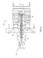
- Injection nozzle assembly 38 includes a fuel inlet portion 44 having a valve assembly 45. Injection nozzle assembly 38 also includes a centerbody 54 that defines, in part, a primary mixing zone 58. Fuel and air are mixed, enter into primary mixing zone 58 and pass into combustion chamber 34 to be ignited. During certain operational modes, a portion of the fuel is directed through a secondary fuel nozzle 63 before being reintroduced into primary mixing zone 58.
- Secondary fuel nozzle 63 includes an upstream end 66 that is fluidly linked to fuel inlet 44 and a downstream end 67 that leads toward combustion chamber 34. Downstream end 67 includes a plurality of outlets, one of which is indicated at 69 in FIG. 4 , for discharging purge air during and between various operational modes. The discharge of purge air is carried out to substantially limit a flame from entering into secondary fuel nozzle 63.
- injection nozzle assembly 38 is also shown to include a swirler member 74 arranged at downstream end 67 of secondary fuel nozzle 63.
- Swirler member 74 is configured to impart a "swirl" to the fuel/air mixture passing from primary mixing zone 58 to combustion chamber 34. The "swirl" enhances mixing of the fuel and air resulting in a more complete combustion.
- Swirler member 74 includes a hub portion 84 and a plurality of vanes indicated generally at 86. Vanes 86 extend radially outward from hub member 84 and include a pitch and profile configured to impart a desired "swirl" to the fuel/air mixture passing through primary mixing zone 58.
- swirler member 74 includes a first flow conditioning band 94 and a second flow conditioning band 95 ( FIG. 4 ).
- First and second flow conditioning bands 94 and 95 extend radially about hub portion 84 and between the plurality of vanes 86 to create an impediment to a portion of the fuel/air mixture passing through primary mixing zone 58. As will be discussed more fully below, the impediment to the fuel/air flow enhances flame stability within combustor 6.
- each flow conditioning band 94, 95 includes a rectangular profile such as indicated at 110 in FIG. 5 .
- Rectangular profile 110 includes first and second vertical sides 112 and 113 that are joined by horizontal sides 114 and 115.
- side 114 and/or side 115 provides an impediment to the flow of fuel/air passing through primary mixing zone 58.
- each flow conditioning band 94, 95 includes an aerodynamic profile such as shown at 120 in FIG. 6 .
- Aerodynamic profile 120 includes first and second generally rounded surfaces 123 and 124 that are joined by opposing curvilinear surfaces 126 and 127 thereby defining an airfoil. In a manner similar to that described above, curvilinear surfaces 126 and 127 provide an impediment to the flow of fuel/air passing through primary mixing zone 58.
- flow conditioning bands 94 and 95 include an aerodynamic profile such as shown at 130 in FIG. 7 . Aerodynamic profile 130 includes a first generally triangular portion 134 having first and second angled surfaces 136 and 137, and a second generally triangular portion 139 having first and second angled surfaces 141 and 142. At this point it should be understood that the above described geometries are exemplary.
- flow conditioning bands in accordance with exemplary embodiments can take on a variety of forms, shapes, and/or dimensions. It should also be understood that flow conditioning bands 94 and 95 could include similar profiles or each be formed with a different profile. For example, flow conditioning band 94 could include a rectangular profile while flow conditioning band 95 could include an aerodynamic profile.
- each of the above profiles establishes a particular impediment to the fuel/air mixture flow passing through primary mixing zone 58 to achieve a more stable flame front.
- the fuel/air mixture flow as a non-uniform velocity profile 147 with a mid-span peak 148 and a steep velocity gradient toward an inner radius of the injection nozzle assembly.
- the flow conditioning bands in accordance with the exemplary embodiments provide an injection nozzle assembly that generates a fuel/air mixture that possesses a velocity profile 160 having a substantially constant velocity portion 162.
- Substantially constant velocity portion 162 has been shown to create a more stable flame front that allows for increased turndown of the fuel thereby improving the blow out point and lowering NOx emissions.
- the exemplary embodiments can be employed in a wide array of gas turbomachine and are not limited to the examples shown. Also, while the injection nozzle assembly is shown and described as including two flow conditioning bands, it should be apparent that number and position of the flow condition bands could vary depending upon the desired velocity profile. Finally, it should be understood that the profiles shown for the flow condition band are exemplary and could include various other geometries.
Landscapes
- Engineering & Computer Science (AREA)
- Chemical & Material Sciences (AREA)
- Combustion & Propulsion (AREA)
- Mechanical Engineering (AREA)
- General Engineering & Computer Science (AREA)
- Turbine Rotor Nozzle Sealing (AREA)
- Structures Of Non-Positive Displacement Pumps (AREA)
Applications Claiming Priority (1)
| Application Number | Priority Date | Filing Date | Title |
|---|---|---|---|
| US12/775,679 US20110271683A1 (en) | 2010-05-07 | 2010-05-07 | Turbomachine injection nozzle assembly |
Publications (1)
| Publication Number | Publication Date |
|---|---|
| EP2385305A2 true EP2385305A2 (fr) | 2011-11-09 |
Family
ID=44501759
Family Applications (1)
| Application Number | Title | Priority Date | Filing Date |
|---|---|---|---|
| EP11165066A Withdrawn EP2385305A2 (fr) | 2010-05-07 | 2011-05-06 | Ensemble de buse à injection de turbomachine |
Country Status (4)
| Country | Link |
|---|---|
| US (1) | US20110271683A1 (fr) |
| EP (1) | EP2385305A2 (fr) |
| JP (1) | JP2011237168A (fr) |
| CN (1) | CN102261659A (fr) |
Families Citing this family (2)
| Publication number | Priority date | Publication date | Assignee | Title |
|---|---|---|---|---|
| CN103159231B (zh) * | 2013-02-06 | 2015-03-04 | 中国大唐集团环境技术有限公司 | 一种尿素热解反应器 |
| US9500367B2 (en) | 2013-11-11 | 2016-11-22 | General Electric Company | Combustion casing manifold for high pressure air delivery to a fuel nozzle pilot system |
Family Cites Families (2)
| Publication number | Priority date | Publication date | Assignee | Title |
|---|---|---|---|---|
| DE68923413T2 (de) * | 1988-09-07 | 1996-04-04 | Hitachi Ltd | Kraftstoff-Luftvormischvorrichtung für eine Gasturbine. |
| US20080078182A1 (en) * | 2006-09-29 | 2008-04-03 | Andrei Tristan Evulet | Premixing device, gas turbines comprising the premixing device, and methods of use |
-
2010
- 2010-05-07 US US12/775,679 patent/US20110271683A1/en not_active Abandoned
-
2011
- 2011-04-22 JP JP2011095573A patent/JP2011237168A/ja not_active Withdrawn
- 2011-05-05 CN CN2011101248513A patent/CN102261659A/zh active Pending
- 2011-05-06 EP EP11165066A patent/EP2385305A2/fr not_active Withdrawn
Non-Patent Citations (1)
| Title |
|---|
| None |
Also Published As
| Publication number | Publication date |
|---|---|
| CN102261659A (zh) | 2011-11-30 |
| JP2011237168A (ja) | 2011-11-24 |
| US20110271683A1 (en) | 2011-11-10 |
Similar Documents
| Publication | Publication Date | Title |
|---|---|---|
| US8904802B2 (en) | Turbomachine combustor assembly including a vortex modification system | |
| JP5947515B2 (ja) | 渦発生装置を有する混合管要素を備えたターボ機械 | |
| US8904798B2 (en) | Combustor | |
| US8261555B2 (en) | Injection nozzle for a turbomachine | |
| CN101943060B (zh) | 用于组装燃气涡轮发动机的方法、燃料喷嘴以及燃气涡轮系统 | |
| US20130036743A1 (en) | Turbomachine combustor assembly | |
| US9951956B2 (en) | Fuel nozzle assembly having a premix fuel stabilizer | |
| CN103206727A (zh) | 具有可变旋流器的燃气涡轮机燃烧室的空气-燃料预混器 | |
| US10240795B2 (en) | Pilot burner having burner face with radially offset recess | |
| US8291705B2 (en) | Ultra low injection angle fuel holes in a combustor fuel nozzle | |
| EP2383517A2 (fr) | Ensemble de buse à injection refroidie pour turbine à gaz | |
| EP2565541A2 (fr) | Ensemble buse d'injection pour une turbomachine à gaz | |
| US10837639B2 (en) | Burner for a gas turbine | |
| US20120240592A1 (en) | Combustor with Fuel Nozzle Liner Having Chevron Ribs | |
| CN103917826A (zh) | 涡轮机燃烧器组件和操作涡轮机的方法 | |
| EP2385305A2 (fr) | Ensemble de buse à injection de turbomachine | |
| US20150338101A1 (en) | Turbomachine combustor including a combustor sleeve baffle | |
| US20230194088A1 (en) | Combustor with dilution openings | |
| US12339006B1 (en) | Turbine engine having a combustion section with a fuel nozzle assembly | |
| US20250020324A1 (en) | Combustor with dilution openings | |
| US20160053681A1 (en) | Liquid fuel combustor having an oxygen-depleted gas (odg) injection system for a gas turbomachine |
Legal Events
| Date | Code | Title | Description |
|---|---|---|---|
| AK | Designated contracting states |
Kind code of ref document: A2 Designated state(s): AL AT BE BG CH CY CZ DE DK EE ES FI FR GB GR HR HU IE IS IT LI LT LU LV MC MK MT NL NO PL PT RO RS SE SI SK SM TR |
|
| AX | Request for extension of the european patent |
Extension state: BA ME |
|
| PUAI | Public reference made under article 153(3) epc to a published international application that has entered the european phase |
Free format text: ORIGINAL CODE: 0009012 |
|
| STAA | Information on the status of an ep patent application or granted ep patent |
Free format text: STATUS: THE APPLICATION IS DEEMED TO BE WITHDRAWN |
|
| 18D | Application deemed to be withdrawn |
Effective date: 20131203 |