EP2385351A2 - Vertikale Profilanzeige mit variablen Anzeigebegrenzungen - Google Patents
Vertikale Profilanzeige mit variablen Anzeigebegrenzungen Download PDFInfo
- Publication number
- EP2385351A2 EP2385351A2 EP11154857A EP11154857A EP2385351A2 EP 2385351 A2 EP2385351 A2 EP 2385351A2 EP 11154857 A EP11154857 A EP 11154857A EP 11154857 A EP11154857 A EP 11154857A EP 2385351 A2 EP2385351 A2 EP 2385351A2
- Authority
- EP
- European Patent Office
- Prior art keywords
- aircraft
- display
- neighboring
- host
- vsd
- Prior art date
- Legal status (The legal status is an assumption and is not a legal conclusion. Google has not performed a legal analysis and makes no representation as to the accuracy of the status listed.)
- Withdrawn
Links
Images



Classifications
-
- G—PHYSICS
- G01—MEASURING; TESTING
- G01C—MEASURING DISTANCES, LEVELS OR BEARINGS; SURVEYING; NAVIGATION; GYROSCOPIC INSTRUMENTS; PHOTOGRAMMETRY OR VIDEOGRAMMETRY
- G01C23/00—Combined instruments indicating more than one navigational value, e.g. for aircraft; Combined measuring devices for measuring two or more variables of movement, e.g. distance, speed or acceleration
-
- G—PHYSICS
- G08—SIGNALLING
- G08G—TRAFFIC CONTROL SYSTEMS
- G08G5/00—Traffic control systems for aircraft
- G08G5/20—Arrangements for acquiring, generating, sharing or displaying traffic information
- G08G5/21—Arrangements for acquiring, generating, sharing or displaying traffic information located onboard the aircraft
-
- G—PHYSICS
- G08—SIGNALLING
- G08G—TRAFFIC CONTROL SYSTEMS
- G08G5/00—Traffic control systems for aircraft
- G08G5/20—Arrangements for acquiring, generating, sharing or displaying traffic information
- G08G5/25—Transmission of traffic-related information between aircraft
-
- G—PHYSICS
- G08—SIGNALLING
- G08G—TRAFFIC CONTROL SYSTEMS
- G08G5/00—Traffic control systems for aircraft
- G08G5/70—Arrangements for monitoring traffic-related situations or conditions
- G08G5/72—Arrangements for monitoring traffic-related situations or conditions for monitoring traffic
- G08G5/723—Arrangements for monitoring traffic-related situations or conditions for monitoring traffic from the aircraft
Definitions
- the disclosed invention was made with United States Government support under contract number MOA DTFAWA-09-A-00001, Mod 0003 (awarded by the Federal Aviation Authority). The United States Government has certain rights in the disclosed invention.
- Embodiments of the subject matter described herein relate generally to avionics systems such as flight display systems. More particularly, embodiments of the subject matter relate to a vertical profile display for a host aircraft.
- the in-trail procedure is a protocol followed by an aircraft that desires to change its current flight level to a new flight level by descending or climbing in front of or behind one or more potentially blocking aircraft that are flying at an intervening flight level.
- ITP in-trail procedure
- certain conditions must be satisfied before the flight crew member issues a request for clearance to proceed with the flight level change. Whether or not the conditions are satisfied will depend on a number of dynamically changing factors associated with the host aircraft and other aircraft, such as the current geographic position of the aircraft, the current speed of the aircraft, the current heading of the aircraft, the desired new flight level, and the current flight level.
- Modem flight deck instrumentation might include a vertical profile display or a vertical situation display (VSD) that provides a two-dimensional representation of an aircraft, the aircraft vertical flight plan, and neighboring aircraft.
- VSDs typically include a number of parameters and visual indicators that enable the pilot to form a quick mental picture of the vertical situation of the host aircraft.
- VSDs may include displays of an aircraft symbol, the aircraft altitude, the vertical flight plan, and terrain.
- a member of the aircraft flight crew can obtain information related to the vertical situation of the aircraft relative to the terrain with a simple glance at the VSD.
- a VSD could be used to identify the vertical position of potentially blocking aircraft for purposes of the ITP. Even if a VSD is deployed, however, the flight crew member will still need to mentally interpret the traffic situation and/or perform manual calculations related to the designation of potentially blocking aircraft and related to the determination of whether the conditions exist requiring the ITP protocol be used for a desired flight level change.
- Conventional VSDs display all air traffic within some predetermined maximum range relative to the host aircraft. Accordingly, a conventional VSD might become cluttered with many graphical representations of neighboring aircraft, whether or not such neighboring aircraft are relevant for purposes of the ITP.
- a method for displaying aircraft traffic information on a display element of a host aircraft obtains current flight status data of the host aircraft and current flight status data of neighboring aircraft located within a designated range relative to the host aircraft.
- the method also obtains a display filter boundary relative to the host aircraft, where the display filter boundary resides within the designated range.
- the method continues by analyzing the current flight status data of the neighboring aircraft located within the designated range to identify neighboring aircraft located within the display filter boundary.
- the method generates image rendering display commands for a VSD, based upon the current flight status data of the host aircraft and the current flight status data of the neighboring aircraft located within the display filter boundary.
- the VSD includes graphical representations of the host aircraft and the neighboring aircraft located within the display filter boundary, and the VSD is devoid of graphical representations of any neighboring aircraft located outside the display filter boundary.
- the VSD is rendered on the display element of the host aircraft.
- the display system includes: instrumentation configured to obtain aircraft data comprising current flight status data of the host aircraft and current flight status data of neighboring aircraft located near the host aircraft; a processor coupled to the instrumentation; and a display element coupled to the processor.
- the processor is configured to process and filter the aircraft data, using lateral boundary criteria for the host aircraft, to identify a proper subset of the neighboring aircraft.
- the processor is also configured to generate image rendering display commands based upon the current flight status data of the host aircraft and based upon the current flight status data of neighboring aircraft included in the proper subset.
- the display element is configured to receive the image rendering display commands and, in response thereto, to render a VSD that includes graphical representations of the host aircraft and each neighboring aircraft included the proper subset.
- Another method for displaying aircraft traffic information on a display element of a host aircraft begins by obtaining current flight status data of the host aircraft and current flight status data of neighboring aircraft located near the host aircraft. The method continues by receiving a user command that indicates an activation status of a lateral filter display mode.
- the current flight status data of the neighboring aircraft is filtered, using lateral filtering criteria for the host aircraft, to identify a proper subset of the neighboring aircraft, and a filtered VSD is rendered with graphical representations of those neighboring aircraft included in the proper subset.
- an unfiltered VSD is rendered with graphical representations of all neighboring aircraft.
- FIG. 1 is a schematic representation of an exemplary embodiment of a flight deck display system
- FIG. 2 is a schematic representation of an exemplary plan view display that depicts a host aircraft and surrounding aircraft traffic;
- FIG. 3 is a schematic representation of an exemplary VSD that corresponds to the plan view display shown in FIG. 2 ;
- FIG. 4 is a flow chart that illustrates an exemplary embodiment of a traffic display process suitable for use with a flight deck display system
- FIG. 5 is a schematic representation of an exemplary plan view display that depicts a host aircraft, surrounding aircraft traffic, and lateral display filtering boundaries;
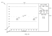
- FIG. 6 is a schematic representation of an exemplary filtered VSD that corresponds to the plan view display shown in FIG. 5 ;
- FIG. 7 is a schematic representation of an exemplary plan view display that depicts a host aircraft, surrounding aircraft traffic, and asymmetric lateral display filtering boundaries;
- FIG. 8 is a schematic representation of an exemplary filtered VSD that corresponds to the plan view display shown in FIG. 7 .
- an embodiment of a system or a component may employ various integrated circuit components, e.g., memory elements, digital signal processing elements, logic elements, look-up tables, or the like, which may carry out a variety of functions under the control of one or more microprocessors or other control devices.
- integrated circuit components e.g., memory elements, digital signal processing elements, logic elements, look-up tables, or the like, which may carry out a variety of functions under the control of one or more microprocessors or other control devices.
- the subject matter described herein relates to a vertical profile display (also referred to as a vertical situation display or VSD) that is suitable for use onboard an aircraft.
- VSD vertical situation display
- the VSD is generated and rendered such that the amount of displayed neighboring aircraft is "filtered" to reduce display clutter.
- the neighboring aircraft are filtered in accordance with predefined, user-entered, or dynamically calculated boundaries that are measured relative to the host aircraft.
- traditional VSD deployments include a fixed lateral width for the vertical presentation, i.e., a fixed volume of airspace that is considered for display of traffic targets on the VSD.
- the flight crew may be advantageous for the flight crew to vary the lateral swath width of the VSD, depending on a number of factors such as traffic density, geometry of the track system, etc. For example, for closely spaced narrow tracks that are heavily congested with traffic it may be advantageous for the flight crew to de-clutter the VSD by manually selecting a narrower lateral display width.
- a VSD having the features and characteristics described herein may be used in a normal navigation mode, an ITP mode, or both.
- the distance between the host aircraft and neighboring aircraft is expressed in a traditional manner, e.g., conventional range in nautical miles.
- the distance between the host aircraft and neighboring aircraft is expressed using "ITP distance" or some other defined units that are suitable for purposes of the ITP.
- NASA Document National Aeronautics and Space Administration
- the NASA Document specifies that the host aircraft and any neighboring aircraft of interest (i.e., a potentially blocking aircraft) must be "same direction" aircraft in order for an ITP flight level change to be requested.
- "same direction" tracks are intersecting tracks (or portions thereof) having an angular difference of less than 45 degrees.
- the ITP is a protocol that can be followed when an aircraft seeks to change its flight level to a new flight level in the presence of a potentially blocking aircraft located at an intervening flight level.
- the "ITP is intended to enable altitude changes that are otherwise blocked when aircraft are spaced at less than current separation standards at altitudes between the current and desired altitudes of a requesting aircraft.”
- the ITP specifies some minimum separation between aircraft at the current and requested flight levels, to ensure safe altitude changes.
- the ITP specifies certain criteria that must be satisfied before the host aircraft can issue a request for ITP flight level change (such requests are issued to Air Traffic Control (ATC)).
- ATC Air Traffic Control
- the NASA Document indicates the following ITP initiation criteria, where at least one of two conditions must be met: (1) if the ITP distance to a reference aircraft is greater than or equal to 15 nautical miles, then the groundspeed differential between the two aircraft must be less than or equal to 20 knots; or (2) if the ITP distance to a reference aircraft is greater than or equal to 20 nautical miles, then the groundspeed differential between the two aircraft must be less than or equal to 30 knots.
- the NASA Document defines the ITP distance as "the difference in distance to a common point along each aircraft's track.”
- the ITP distance represents one appropriate measure of distance between the host aircraft and neighboring aircraft (which may or may not be “reference aircraft” as defined by the NASA Document).
- other distance metrics, distance measures, or relative spacing metrics could be used with VSDs.
- the system could contemplate linear distance, time, aircraft acceleration, relative speed, closing rate, and/or other measureable or computable values that are dependent on the current geographic position, speed, acceleration, heading, attitude, or other operating status of the aircraft.
- FIG. 1 is a schematic representation of an exemplary embodiment of a flight deck display system 100 that is suitable for use with a vehicle such as an aircraft.
- the display system 100 is located onboard the host aircraft, i.e., the various components and elements of the display system 100 reside within the host aircraft, are carried by the host aircraft, or are attached to the host aircraft.
- the illustrated embodiment of the display system 100 includes, without limitation: at least one processor 102; an appropriate amount of memory 104; a display element 106; a graphics system 108; a user interface 110; a data communication module 112; a lateral range filtering and processing module 114; and at least one source of flight status data 116.
- These elements of the display system 100 may be coupled together by a suitable interconnection architecture 118 that accommodates data communication, the transmission of control or command signals, and/or the delivery of operating power within the display system 100.
- FIG. 1 is a simplified representation of the display system 100 that will be used for purposes of explanation and ease of description, and that FIG. 1 is not intended to limit the application or scope of the subject matter in any way.
- FIG. 1 depicts the display system 100 as a single unit, the individual elements and components of the display system 100 could be implemented in a distributed manner using any number of physically distinct pieces of hardware or equipment.
- the processor 102 may be implemented or realized with a general purpose processor, a content addressable memory, a digital signal processor, an application specific integrated circuit, a field programmable gate array, any suitable programmable logic device, discrete gate or transistor logic, discrete hardware components, or any combination designed to perform the functions described here.
- a processor device may be realized as a microprocessor, a controller, a microcontroller, or a state machine.
- a processor device may be implemented as a combination of computing devices, e.g., a combination of a digital signal processor and a microprocessor, a plurality of microprocessors, one or more microprocessors in conjunction with a digital signal processor core, or any other such configuration.
- the processor 102 and/or the lateral range filtering and processing module 114 obtains, processes, and "filters" aircraft data, which includes current flight status data (of the host aircraft and one or more neighboring aircraft), to identify those neighboring aircraft that are located within certain lateral boundaries relative to the host aircraft, for purposes of generating a filtered VSD that has less graphical clutter.
- the memory 104 may be realized as RAM memory, flash memory, EPROM memory, EEPROM memory, registers, a hard disk, a removable disk, a CD-ROM, or any other form of storage medium known in the art.
- the memory 104 can be coupled to the processor 102 such that the processor 102 can read information from, and write information to, the memory 104.
- the memory 104 may be integral to the processor 102.
- the processor 102 and the memory 104 may reside in an ASIC.
- a functional or logical module/component of the display system 100 might be realized using program code that is maintained in the memory 104.
- the graphics system 108, the data communication module 112, or the lateral range filtering and processing module 114 may have associated software program components that are stored in the memory 104.
- the memory 104 can be used to store data utilized to support the operation of the display system 100, as will become apparent from the following description.
- the display element 106 is coupled to the graphics system 108.
- the graphics system 108 is coupled to the processor 102 such that the processor 102 and the graphics system 108 cooperate to display, render, or otherwise convey one or more graphical representations, synthetic displays, graphical icons, visual symbology, or images associated with operation of the host aircraft on the display element 106, as described in greater detail below.
- An embodiment of the display system 100 may utilize existing graphics processing techniques and technologies in conjunction with the graphics system 108.
- the graphics system 108 may be suitably configured to support well known graphics technologies such as, without limitation, VGA, SVGA, UVGA, or the like.
- the display element 106 is realized as an electronic display configured to graphically display flight information or other data associated with operation of the host aircraft under control of the graphics system 108.
- the display element 106 could also be implemented as a virtual display of the type used with head up display technology.
- the display element 106 could be integrated in equipment worn or carried by the user, e.g., a display mounted to eyewear, headwear, or the like.
- the processor 102 and/or the graphics system 108 produces image rendering display commands that are received by the display element 106 for purposes of rendering VSDs.
- the display element 106 is usually located within a cockpit of the host aircraft. It will be appreciated that although FIG. 1 shows a single display element 106, in practice, additional display devices may be present onboard the host aircraft.
- the illustrated embodiment of the display system 100 includes a user interface 110, which is suitably configured to receive input from a user (e.g., a pilot) and, in response to user-entered data, supply appropriate command signals to the processor 102.
- the user interface 110 may be any one, or any combination, of various known user interface devices or technologies, including, but not limited to: a cursor control device such as a mouse, a trackball, or joystick; a keyboard; buttons; switches; or knobs.
- the user interface 110 may cooperate with the display element 106 and the graphics system 108 to provide a graphical user interface.
- the user interface 110 could be implemented as a graphical user interface rendered on the display element 106.
- the display element 106 implements touch-sensitive technology for purposes of the user interface 110.
- a user can manipulate the user interface 110 by moving a cursor symbol rendered on the display element 106 and/or by physically interacting with the display element 106 itself, and the user may use a keyboard to, among other things, input textual data.
- the user could manipulate the user interface 110 to enter a desired or requested new flight level into the display system 100, to enter lateral boundary values and/or other lateral boundary criteria associated with the rendering of a VSD, and to select VSD presentation modes.
- the data communication module 112 is suitably configured to support data communication between the host aircraft and one or more remote systems. More specifically, the data communication module 112 is used to receive current flight status data 120 of other aircraft that are near the host aircraft. In this regard, the data communication module 112 represents instrumentation that obtains aircraft data used by the display system 100. In particular embodiments, the data communication module 112 is implemented as an aircraft-to-aircraft data communication module that receives flight status data from an aircraft other than the host aircraft.
- the data communication module 112 may be configured for compatibility with Automatic Dependant Surveillance-Broadcast (ADS-B) technology, with Traffic and Collision Avoidance System (TCAS) technology, and/or with similar technologies. In other embodiments the data communication module 112 may also be compatible with Traffic Information Service-Broadcast (TIS-B) technology.
- ADS-B Automatic Dependant Surveillance-Broadcast
- TCAS Traffic and Collision Avoidance System
- TCAS Traffic Information Service-Broadcast
- the flight status data 120 of the neighboring aircraft may include, without limitation: airspeed data; groundspeed data; altitude data; attitude data, including pitch data and roll data; yaw data; geographic position data, such as GPS data; time/date information; heading information; weather information; flight path data; track data; radar altitude data; geometric altitude data; wind speed data; wind direction data; etc.
- the display system 100 is suitably designed to process the flight status data 120 in the manner described in more detail herein. In particular, the display system 100 can use the flight status data 120 when rendering a VSD on the display element 106.
- the lateral range filtering and processing module 114 is configured to perform various operations, calculations, data analysis, and other functions associated with the generation of VSDs.
- the lateral range filtering and processing module 114 may be suitably configured to calculate or otherwise obtain lateral boundaries or lateral boundary criteria that influences the manner in which neighboring aircraft are rendered on the VSD.
- the lateral range filtering and processing module 114 may be disabled or deactivated (by the user or automatically) if so desired such that the VSD includes graphical representations of all of the neighboring aircraft located within a designated or selected range relative to the host aircraft.
- the display system 100 also processes the current flight status data of the host aircraft.
- the sources of flight status data 116 generate, measure, and/or provide different types of data related to the operational status of the host aircraft, the environment in which the host aircraft is operating, flight parameters, and the like.
- the sources of flight status data 116 represent instrumentation that obtains aircraft data used by the display system 100.
- the sources of flight status data 116 may be realized using line replaceable units (LRUs), transducers, accelerometers, instruments, sensors, and other well known devices.
- LRUs line replaceable units
- the data provided by the sources of flight status data 116 may include, without limitation: airspeed data; groundspeed data; altitude data; attitude data, including pitch data and roll data; yaw data; geographic position data, such as GPS data; time/date information; heading information; weather information; flight path data; track data; radar altitude data; geometric altitude data; wind speed data; wind direction data; etc.
- the display system 100 is suitably designed to process data obtained from the sources of flight status data 116 in the manner described in more detail herein. In particular, the display system 100 can use the flight status data of the host aircraft when rendering VSDs.
- a VSD provides a graphical representation of the host aircraft and neighboring aircraft using a side or vertical profile perspective.
- the display system 100 may also be suitably configured to generate and render plan view displays of the air traffic near the host aircraft.
- FIG. 2 is a schematic representation of an exemplary plan view display 200 that depicts a host aircraft and surrounding aircraft traffic
- FIG. 3 is a schematic representation of an exemplary VSD 300 that corresponds to the plan view display 200.
- the plan view display 200 and the VSD 300 represent snapshots of dynamic displays taken at a particular moment in time.
- the plan view display 200 corresponds to a top-down view of the airspace near the host aircraft.
- the illustrated embodiment of the plan view display 200 generally includes, without limitation, graphical representations of the following items: the host aircraft 202; a range circle 204; a range marker 206; and a plurality of neighboring aircraft 208, 210, 212, 214, 216, 218.
- the plan view display 200 also includes identifiers or labels for each neighboring aircraft. For example, each neighboring aircraft could be identified by carrier and tail number.
- the range marker 206 includes alphanumeric indicia of a designated range (100 nautical miles for this example) relative to the host aircraft 202.
- plan view display 200 includes graphical representations of all the neighboring aircraft located within the designated range, assuming that the system has knowledge of all those neighboring aircraft.
- the graphical representation of the host aircraft 202 remains in a fixed position on the plan view display 200.
- the VSD 300 corresponds to a side view of the airspace near the host aircraft.
- This exemplary VSD 300 generally includes a main display area 302, a data entry and notification area 304, and a traffic status area 306.
- the main display area 302 contains graphical representations of the aircraft.
- the data entry and notification area 304 may be dynamic in nature such that a variety of notifications, data entry fields, information, and graphical items can be displayed at different times to accommodate changing conditions, user commands, display modes, and the like.
- This particular embodiment includes graphical "radio buttons" in the data entry and notification area 304 ⁇ these radio buttons indicate the current lateral filter display mode of the VSD 300 (OFF indicates that the lateral filter display mode is not active; MAN indicates that the manual lateral filter display mode is activated; and AUTO indicates that the automatic lateral filter display mode is activated).
- OFF indicates that the lateral filter display mode is not active
- MAN indicates that the manual lateral filter display mode is activated
- AUTO indicates that the automatic lateral filter display mode is activated.
- the lateral filter display mode is deactivated for the VSD 300 depicted in FIG. 3 .
- the main display area 302 includes graphical representations of all the neighboring aircraft located within the designated range (100 nautical miles), which is consistent with the plan view display 200.
- the traffic status area 306 is utilized to list the neighboring aircraft that appear in the main display area 302, using any appropriate identifier or nomenclature. This example identifies the other aircraft by carrier and tail number (ABC 84, YYZ 51, LAL 65, MMT45, YYZ 58, and ABC 79).
- the traffic status area 306 can be used to provide detailed information about a single aircraft that has been selected by the user. For example, if the user selects the LAL 65 aircraft, then data associated with that aircraft (such as altitude, ground speed, ITP distance, and the like) can be presented in the traffic status area 306.
- the illustrated embodiment of the main display area 302 of the VSD 300 generally includes, without limitation, graphical representations of the following items: an altitude scale 320 for the host aircraft and the other aircraft; a lateral distance scale 322 for the host aircraft and the other aircraft (which may be expressed in ITP distance or "standard” (range) distance using nautical miles as the unit of measurement); the host aircraft 202'; and neighboring aircraft 208', 210', 212', 214', 216', 218'.
- the prime notation is used for numbering consistency with FIG. 2 ⁇ the neighboring aircraft depicted in the VSD 300 are intended to represent their counterpart neighboring aircraft in the plan view display 200.
- the altitude (or flight level) scale 320 may include alphanumeric indicia of altitude values in any convenient scale (in FIG. 3 , the altitude scale 320 includes numerical values expressed in hundreds of feet, in increments of one thousand feet). In this embodiment, the altitude scale 320 is rendered as a scrollable tape such that the host aircraft 202' is always rendered at the same vertical position on the VSD 300. At the time depicted in FIG. 3 , the current flight level of the host aircraft 202' is 30,000 feet.
- the lateral distance scale 322 may include alphanumeric indicia of distance values in any convenient scale (in FIG. 3 , the lateral distance scale 322 includes numerical values that represent distance relative to the host aircraft 202', in increments of twenty nautical miles).
- the lateral distance scale 322 has a zero reference point that corresponds to the current position of the host aircraft.
- the graphical representation of the host aircraft 202' is aligned with the zero lateral distance mark on the lateral distance scale 322. Consequently, the host aircraft 202' and the lateral distance scale 322 are rendered in fixed positions on the VSD 300.
- the altitude scale 320 and the neighboring aircraft 208', 210', 212', 214', 216', 218' can be rendered in a dynamic manner that reflects the changing flight conditions and aircraft positions.
- the graphical representations of the host aircraft 202' and the neighboring aircraft 208', 210', 212', 214', 216', 218' are positioned in the main display area 302 in accordance with the current flight status data of the host aircraft and in accordance with the current flight data of the neighboring aircraft (which may be received by the host aircraft using, for example, ADS-B technology).
- the graphical representations of the neighboring aircraft 208', 210', 212', 214', 216', 218' are positioned on the main display area 302 in a manner that indicates the actual respective altitudes of the neighboring aircraft relative to the host aircraft, and in a manner that indicates the actual distance of interest (e.g., a standard distance measure, the ITP distance, or other suitable distance metric) between the other aircraft and the host aircraft. Consequently, the current distance and vertical separation between the host aircraft and the nearby aircraft can be quickly and easily determined from the VSD 300.
- a standard distance measure e.g., the ITP distance, or other suitable distance metric
- the main display area 302 includes graphical identifiers or labels for the displayed aircraft.
- all displayed aircraft are rendered with their corresponding alphanumeric carrier and tail identifiers.
- the neighboring aircraft 208' is rendered with the text "ABC 84”
- the neighboring aircraft 210' is rendered with the text "YYZ 51”
- the neighboring aircraft 212' is rendered with the text "LAL 65”
- the neighboring aircraft 214' is rendered with the text "MMT 45”
- the neighboring aircraft 216' is rendered with the text "YYZ 58”
- the neighboring aircraft 218' is rendered with the text "ABC 79".
- the airline flight number may also be used to identify the displayed aircraft.
- the main display area 302 also includes graphical indicia of certain flight status information for neighboring or reference aircraft.
- a reference aircraft could be rendered with text that indicates its current ITP distance relative to the host aircraft.
- a neighboring aircraft could be rendered with text that indicates its airspeed relative to the host aircraft.
- FIG. 3 depicts an exemplary display screen that appears when display filtering is deactivated. Consequently, the VSD 300 by default will show graphical representations of all the neighboring aircraft located within the designated range (100 nautical miles for this example, as shown in FIG. 2 ). For simplicity, FIG. 3 depicts only six neighboring aircraft and, therefore, the VSD 300 remains relatively uncluttered and easily readable. If, however, a large number of neighboring aircraft are present within the designated range, then the VSD 300 could become difficult to interpret, especially if graphical representations of aircraft are rendered very close to one another and/or overlapping one another. In such situations, the display system 100 or the user could activate a display filtering mode to hide or otherwise remove some of the aircraft icons from the VSD 300.
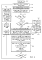
- FIG. 4 is a flow chart that illustrates an exemplary embodiment of a traffic display process 400 suitable for use with a flight deck display system such as the display system 100.
- Process 400 represents one implementation of a method for displaying aircraft traffic information (in the form of a VSD) on an onboard display element of a host aircraft.
- the various tasks performed in connection with process 400 may be performed by software, hardware, firmware, or any combination thereof.
- the following description of process 400 may refer to elements mentioned above in connection with FIGS. 1-3 .
- portions of process 400 may be performed by different elements of the described system, e.g., a processor or processing module, a graphics module, a display element, or a data communication component.
- process 400 may include any number of additional or alternative tasks, the tasks shown in FIG. 4 need not be performed in the illustrated order, and process 400 may be incorporated into a more comprehensive procedure or process having additional functionality not described in detail herein. Moreover, one or more of the tasks shown in FIG. 4 could be omitted from an embodiment of the process 400 as long as the intended overall functionality remains intact.
- the embodiment of the process 400 described here utilizes a lateral boundary filtering scheme wherein neighboring aircraft that are located more than a specified lateral distance (to the port and/or starboard side of the host aircraft) are disregarded for purposes of VSD rendering such that those outlying aircraft are not displayed on the VSD.
- lateral distance is defined as the distance measured from the aircraft's longitudinal axis (the distance to the port or starboard of the longitudinal axis. It should be appreciated that alternate embodiments could employ different filtering schemes that are based upon one or more suitable metrics, including distance measures, time measures, acceleration, velocity, wind speed, etc.
- the process 400 could consider a filtering boundary that is defined by an area or a volume around the host aircraft, e.g., a spherical or tubular boundary surrounding the host aircraft.
- the process 400 could consider a filtering boundary that contemplates the "point-to-point" distance between the host aircraft and each neighboring aircraft.
- the system could also define a user-variable altitude band (altitude filter) around the host aircraft, e.g., 4,000 feet above and below the current altitude of the host aircraft.
- the process 400 could limit the number of aircraft that can be processed and/or stored in memory, such that only the N closest aircraft will be considered (where N is the maximum number of allowable aircraft, e.g., two hundred).
- the display system may support a plurality of different display filtering schemes, and the particular scheme used at any given time could be selected (by the user or automatically in response to the satisfaction of certain predefined criteria).
- process 400 can be performed in a virtually continuous manner at a relatively high refresh rate. For example, an iteration of process 400 could be performed once every two seconds (or less) such that the VDS will be updated in real-time or substantially real time in a dynamic manner.
- This particular embodiment of process 400 begins by obtaining the current flight status data of the host aircraft (task 402).
- the process 400 may also obtain or retrieve a designated, desired, or maximum display range for the VSD (task 404).
- this designated display range may be limited by the data communication capabilities of the host aircraft instrumentation. For the example described above for the VSD 300, the designated maximum display range is 100 nautical miles, although other embodiments could use a different maximum selectable range (e.g., 200 nautical miles).
- the designated maximum display range for the VSD could represent a lateral range measured from the port and starboard sides of the host aircraft, a spherical (or any volumetric) range measured from the host aircraft, or the like. The following description assumes that the designated range represents a lateral range relative to the host aircraft.
- the designated maximum display range for the VSD is predetermined and fixed. In other embodiments, the designated maximum display range is variable. In this regard, the display system could be suitably configured to accommodate user selectable and/or user-entered maximum display ranges. In yet other embodiments, the designated maximum display range is dynamically determined in response to current operating conditions and status of the host aircraft instrumentation (and/or the neighboring aircraft instrumentation).
- the process 400 also receives or otherwise obtains the current flight status data of one or more other aircraft near the host aircraft (task 406).
- task 406 obtains the current flight status data of neighboring aircraft located within the designated display range.
- the process 400 could collect additional aircraft data associated with neighboring aircraft located outside the designated display range, and thereafter discard or ignore that data if so desired.
- task 406 is performed using an appropriate aircraft-to-aircraft data communication technology and related subsystem components located onboard the host aircraft. This enables the host aircraft to receive the current flight status data of the neighboring aircraft directly from those aircraft. Alternatively, the host aircraft could receive this information from a ground-based system.
- aircraft-to-ground technology could be utilized (for example, data for surrounding aircraft is passed to the host aircraft via a data link to a ground facility using TIS-B).
- the display system may allow the user to selectively activate the lateral filter display mode.
- the data entry and notification area 304 includes selectable buttons that enable the user to turn the lateral filter display off, select a manual filtering mode, and select an automatic filtering mode.
- user-entered selections can be obtained using other user interface mechanisms. For this example, if the user selects the OFF button, then the display system will receive an appropriate user command that indicates a deactivation status of the lateral filter display mode.
- the display system When the lateral filter mode is deactivated (query task 408), the display system generates appropriate image rendering display commands for an unfiltered VSD (task 410). Notably, these image rendering display commands will be generated based upon the current flight status data of the host aircraft and the current flight status data of all the neighboring aircraft located within the maximum display range (and also subject to any limitations of the host aircraft traffic computer).
- the process 400 continues by generating and rendering an appropriate unfiltered VSD on an onboard display element of the host aircraft (task 412).
- the visual characteristics and elements of this unfiltered VSD will be responsive or otherwise influenced by the image rendering display commands generated during task 410.
- the unfiltered VSD will include a number of graphical features, visual elements, and graphical representations that are intended for viewing by the pilot and/or other flight crew members.
- the unfiltered VSD might include, without limitation, graphical representations of: the host aircraft; the neighboring aircraft; an altitude or flight level scale; and a lateral distance scale (as described above for FIG. 3 ).
- certain graphical characteristics of the VSD will be determined by or otherwise influenced by the current flight status data of the host aircraft and the current flight status data of the neighboring aircraft.
- a lateral filter display mode if a lateral filter display mode is activated, then the process 400 checks whether automatic or manual filtering has been selected (query task 414). If automatic filtering is enabled, then the process 400 automatically calculates, obtains, or retrieves lateral boundaries, a display filter boundary, or some other lateral boundary criteria to be used for rendering a filtered VSD (task 416). For this example, task 416 calculates, obtains, or retrieves lateral boundaries relative to the host aircraft. These lateral boundaries may be predetermined and stored in memory as fixed values, or they may be calculated as needed based upon current operating conditions. In this regard, the lateral boundaries could be calculated as a function of the maximum lateral range, as a function of the displayed or selected horizontal distance scale, or the like.
- the lateral boundaries may be calculated as a percentage of the designated maximum range.
- one predetermined lateral boundary value could be used when the displayed maximum lateral range is greater than a threshold distance, and a different predetermined lateral boundary value could be used when the displayed maximum lateral range is less than the threshold distance.
- different lateral boundary calculation schemes could be utilized at different times, under different operating conditions, etc.
- a practical embodiment might utilize the following scheme: if the maximum lateral display range displayed is less than 100 nautical miles, then the VSD will show neighboring aircraft located within a lateral distance of 15 nautical miles; and if the maximum lateral display range displayed is greater than or equal to 100 nautical miles, then the VSD will show neighboring aircraft located within a lateral distance that is twenty percent of the maximum lateral display range. In any event, the lateral boundary is less than the displayed maximum lateral range, in an embodiment.
- the process 400 may analyze, process, and/or filter the current aircraft data (e.g., the current flight status data of the neighboring aircraft and the host aircraft) to identify those neighboring aircraft that are located within the lateral boundaries and any vertical boundaries such as those defined by an altitude filter (task 418). Assuming that at least one of the neighboring aircraft resides within the lateral and vertical boundaries, task 418 determines a proper subset of the overall set of neighboring aircraft (i.e., some but not all of the neighboring aircraft located within the maximum display range). In connection with the execution of task 418, the display system may analyze the status of each neighboring aircraft located within the maximum display range, and compare that status against the particular display filtering criteria.
- the current aircraft data e.g., the current flight status data of the neighboring aircraft and the host aircraft
- the display system could calculate the current lateral distance between the host aircraft and the given neighboring aircraft, and then compare the calculated lateral distance to the respective lateral boundary (port or starboard side). If the calculated lateral distance indicates that the neighboring aircraft is positioned inside the lateral boundaries, then the display system can mark or flag that neighboring aircraft as a member of the subset to be displayed on the VSD. If the calculated lateral distance indicates that the neighboring aircraft is positioned outside the lateral boundaries, then the display system can mark or flag that neighboring aircraft as one that should not be displayed on the VSD. The same general procedure can be followed for any upper and lower vertical boundaries.
- the display system generates appropriate image rendering display commands for a filtered VSD (task 420).
- these image rendering display commands will be generated based upon the current flight status data of the host aircraft and the current flight status data of the neighboring aircraft located within the lateral and any vertical boundaries. In other words, only those neighboring aircraft that are members of the identified subset are considered for the filtered VSD.
- the process 400 continues by generating and rendering an appropriate filtered VSD on the display element of the host aircraft (task 422).
- the visual characteristics and elements of this filtered VSD will be responsive or otherwise influenced by the image rendering display commands generated during task 420.
- the filtered VSD will include a number of graphical features, visual elements, and graphical representations that are intended for viewing by the pilot and/or other flight crew members.
- the filtered VSD might include, without limitation, graphical representations of: the host aircraft; the neighboring aircraft located within the lateral boundaries; an altitude or flight level scale; and a lateral distance scale.
- the filtered VSD will be devoid of graphical representations of any neighboring aircraft that are located outside the display filter boundary.
- FIG. 5 and FIG. 6 illustrate one possible scenario where lateral display filtering is active.
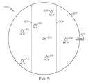
- FIG. 5 is a schematic representation of an exemplary plan view display 500 that depicts a host aircraft, surrounding aircraft traffic, and lateral display filtering boundaries
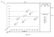
- FIG. 6 is a schematic representation of an exemplary filtered VSD 600 that corresponds to the plan view display 500.
- Most of the features of the plan view display 500 are identical to those described above for the plan view display 200 of FIG. 2 , and common features and elements will not be redundantly described here.
- the plan view display 500 also includes graphical representations of the lateral boundaries, namely, a port side lateral boundary line 502 and a starboard side lateral boundary line 504.
- the lateral boundaries for this example are symmetrical relative to the host aircraft. In other words, the lateral distance from the host aircraft to the port side lateral boundary line 502 is equal to the lateral distance from the host aircraft to the starboard side lateral boundary line 504.
- FIG. 5 illustrates how some (but not all) of the neighboring aircraft are located between the two lateral boundary lines 502, 504.
- the neighboring aircraft 208, 210, 216 are located within the lateral display filtering boundaries.
- the neighboring aircraft 212, 214, 218 are located outside the area defined between the lateral boundary lines 502, 504.
- the plan view display 500 may be suitably generated such that all of the neighboring aircraft 208, 210, 212, 214, 216, 218 are displayed, regardless of their position relative to the lateral boundary lines 502, 504.
- the VSD 600 does not include graphical representations of any neighboring aircraft located outside of the lateral display filtering boundaries. Accordingly, the neighboring aircraft 212, 214, 218 (shown in FIG. 5 ) are not displayed on the VSD 600, and only the neighboring aircraft 208', 210', 216' are rendered on the VSD 600. Compared to the VSD 300, which includes visual representations of all the neighboring aircraft, the VSD 600 is less cluttered and easier to read. In FIG.
- the data entry and notification area 304 indicates that the automatic lateral filter mode is active.
- the VSD 600 includes indicia 602 of the display filter boundaries.
- the lateral boundaries are both 30 nautical miles, relative to the host aircraft. It should be appreciated that this indicia 602 could be rendered elsewhere on the VSD 600.
- the process 400 may proceed by obtaining or otherwise receiving user-entered data (task 416) that defines or is indicative of the display filter boundary, the display filtering criteria, the lateral boundary values, or the like.
- user-entered data indicates a first lateral boundary for the port side of the host aircraft, and a second lateral boundary for the starboard side of the host aircraft. Accommodating individual lateral boundary values in this manner enables the display system to generate a filtered VSD using asymmetric lateral boundaries, relative to the host aircraft.
- the process 400 can then proceed to calculate or otherwise obtain the lateral boundaries to be used for rendering the filtered VSD (task 426). These lateral boundaries may be calculated from or based upon the user-entered lateral boundary values. Indeed, the lateral boundaries obtained during task 426 may be identical to the user-entered data. After the appropriate lateral boundaries are determined, the process 400 may proceed to task 418 and continue to generate and render the filtered VSD in the manner described previously.
- the manual mode allows the user to customize the display filtering characteristics of the VSD to some extent.
- the display system might allow the user to enter any boundary value, or it may provide specific boundary values (in fixed increments or otherwise) from which the user may select for use with the VSD at a given time.
- the display system places upper and lower limits on the user-entered boundary values (e.g., a user-entered boundary value must be within the range of 10-60 nautical miles, or within ten to ninety percent of the maximum lateral range).
- the manual mode enables the user to set a port side lateral boundary value and a starboard side lateral boundary value, independently of one another. Accordingly, the filtered VSD could be generated using symmetrical lateral boundaries (see FIG. 5 and FIG. 6 ) or using asymmetrical lateral boundaries.
- FIG. 7 and FIG. 8 illustrate another scenario where lateral display filtering is active; for this example, the manual filtering display mode has been selected and asymmetrical lateral boundaries have been set.
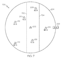
- FIG. 7 is a schematic representation of an exemplary plan view display 700 that depicts the host aircraft, surrounding aircraft traffic, and asymmetric lateral display filtering boundaries
- FIG. 8 is a schematic representation of an exemplary filtered VSD 800 that corresponds to the plan view display 700 shown in FIG. 7 .
- Most of the features of the plan view display 700 are identical to those described above for the plan view display 200 of FIG. 2 , some features of the plan view display 700 are similar to those described above for the plan view display 500 of FIG. 5 , and common features and elements will not be redundantly described here.
- the plan view display 700 also includes graphical representations of the asymmetric lateral boundaries, namely, a port side lateral boundary line 702 and a starboard side lateral boundary line 704. As is apparent from FIG. 7 , the lateral distance from the host aircraft 202 to the port side lateral boundary line 702 is less than the lateral distance from the host aircraft 202 to the starboard side lateral boundary line 704.
- the VSD 800 does not include graphical representations of any neighboring aircraft located outside of the lateral display filtering boundaries. Accordingly, the neighboring aircraft 210, 212, 214, 218 (shown in FIG. 5 ) are not displayed on the VSD 600, and only the neighboring aircraft 208", 216" are rendered on the VSD 800.
- the shorter port side lateral boundary used to generate the VSD 800 results in the removal of the neighboring aircraft 210 from the VSD 800.
- the neighboring aircraft 210 is located beyond the port side lateral boundary 702 and, therefore, the VSD 800 does not include a graphical representation of that aircraft.
- the data entry and notification area 304 indicates that the manual lateral filter mode is active.
- the VSD 800 includes indicia 602 of the individual lateral boundaries.
- the process 400 if it is time to refresh the VSD (query task 428), then the process 400 returns to task 402 to obtain updated data and refresh the display element in response to the updated data.
- the content of the rendered VSD is dynamically updated as the host aircraft continues its flight path.
Landscapes
- Engineering & Computer Science (AREA)
- Aviation & Aerospace Engineering (AREA)
- Physics & Mathematics (AREA)
- General Physics & Mathematics (AREA)
- Radar, Positioning & Navigation (AREA)
- Remote Sensing (AREA)
- Traffic Control Systems (AREA)
Applications Claiming Priority (1)
| Application Number | Priority Date | Filing Date | Title |
|---|---|---|---|
| US12/774,513 US8417397B2 (en) | 2010-05-05 | 2010-05-05 | Vertical profile display with variable display boundaries |
Publications (2)
| Publication Number | Publication Date |
|---|---|
| EP2385351A2 true EP2385351A2 (de) | 2011-11-09 |
| EP2385351A3 EP2385351A3 (de) | 2012-05-09 |
Family
ID=43856266
Family Applications (1)
| Application Number | Title | Priority Date | Filing Date |
|---|---|---|---|
| EP11154857A Withdrawn EP2385351A3 (de) | 2010-05-05 | 2011-02-17 | Vertikale Profilanzeige mit variablen Anzeigebegrenzungen |
Country Status (2)
| Country | Link |
|---|---|
| US (1) | US8417397B2 (de) |
| EP (1) | EP2385351A3 (de) |
Families Citing this family (25)
| Publication number | Priority date | Publication date | Assignee | Title |
|---|---|---|---|---|
| US9330573B2 (en) | 2009-06-25 | 2016-05-03 | Honeywell International Inc. | Automated decision aid tool for prompting a pilot to request a flight level change |
| US8271152B2 (en) * | 2010-03-10 | 2012-09-18 | Honeywell International Inc. | System and method for rendering an onboard aircraft display for use with in-trail procedures |
| US9135829B2 (en) * | 2010-04-30 | 2015-09-15 | The Boeing Company | Distance separation criteria indicator |
| US8417397B2 (en) | 2010-05-05 | 2013-04-09 | Honeywell International Inc. | Vertical profile display with variable display boundaries |
| FR2965087B1 (fr) * | 2010-09-21 | 2013-05-17 | Dassault Aviat | Dispositif d'assistance a l'equipage d'un aeronef lors de changements de niveau de vol de celui-ci |
| US8626428B2 (en) * | 2011-06-28 | 2014-01-07 | Honeywell International Inc. | Selectable display of aircraft traffic on tracks |
| US8478513B1 (en) | 2012-01-20 | 2013-07-02 | Honeywell International Inc. | System and method for displaying degraded traffic data on an in-trail procedure (ITP) display |
| US8554394B2 (en) | 2012-02-28 | 2013-10-08 | Honeywell International Inc. | System and method for rendering an aircraft cockpit display for use with an in-trail procedure (ITP) |
| US8781649B2 (en) | 2012-03-19 | 2014-07-15 | Honeywell International Inc. | System and method for displaying in-trail procedure (ITP) opportunities on an aircraft cockpit display |
| US9234982B2 (en) * | 2012-08-06 | 2016-01-12 | Honeywell International Inc. | Aircraft systems and methods for displaying weather information along a flight path |
| US9297895B2 (en) * | 2012-08-30 | 2016-03-29 | Honeywell International Inc. | Systems and methods for in-trail opportunity window estimator |
| US9070283B2 (en) | 2013-01-29 | 2015-06-30 | Honeywell International Inc. | Flight deck display systems and methods for generating in-trail procedure windows including aircraft flight path symbology |
| US9076326B2 (en) * | 2013-02-21 | 2015-07-07 | Honeywell International Inc. | Systems and methods for traffic prioritization |
| US9171472B2 (en) * | 2013-04-09 | 2015-10-27 | Honeywell International Inc. | System and method for displaying symbology on an in-trail procedure display graphically and textually representative of a vertical traffic scenario and air-traffic-control negotiation |
| US20140354455A1 (en) * | 2013-05-31 | 2014-12-04 | Honeywell International Inc. | System and method for increasing situational awareness by displaying altitude filter limit lines on a vertical situation display |
| US10495783B2 (en) * | 2014-07-08 | 2019-12-03 | Honeywell International Inc. | Vertical profile display including weather blocks |
| FR3026508B1 (fr) * | 2014-09-26 | 2017-11-03 | Thales Sa | Aide contextuelle a la gestion du vol |
| US9576481B2 (en) * | 2015-04-30 | 2017-02-21 | Here Global B.V. | Method and system for intelligent traffic jam detection |
| CN108292477B (zh) * | 2016-08-01 | 2021-10-29 | 霍尼韦尔国际公司 | 用于偷听数据或语音通信的便携式数据链路装备 |
| US11408975B2 (en) | 2016-09-14 | 2022-08-09 | Honeywell International Inc. | Display device for vertical presentation of forecast weather |
| WO2018237204A1 (en) * | 2017-06-21 | 2018-12-27 | Airspace Systems Inc. | System and method for broadcasting the location of low altitude objects |
| US10490089B2 (en) | 2017-07-12 | 2019-11-26 | Honeywell International Inc. | Cockpit display of traffic information (CDTI) assisted visual separation employing a vertical situation display |
| US20200013293A1 (en) * | 2018-07-03 | 2020-01-09 | Honeywell International Inc. | Aircraft hazard information system |
| US11320842B2 (en) * | 2018-10-01 | 2022-05-03 | Rockwell Collins, Inc. | Systems and methods for optimized cruise vertical path |
| US11538203B2 (en) * | 2021-05-10 | 2022-12-27 | Honeywell International Inc. | Capability envelope display methods and systems |
Family Cites Families (57)
| Publication number | Priority date | Publication date | Assignee | Title |
|---|---|---|---|---|
| US3875379A (en) | 1971-05-03 | 1975-04-01 | Carl W Vietor | Terminal airways traffic control system |
| US5077673A (en) | 1990-01-09 | 1991-12-31 | Ryan International Corp. | Aircraft traffic alert and collision avoidance device |
| US6314366B1 (en) | 1993-05-14 | 2001-11-06 | Tom S. Farmakis | Satellite based collision avoidance system |
| US5574647A (en) | 1993-10-04 | 1996-11-12 | Honeywell Inc. | Apparatus and method for computing wind-sensitive optimum altitude steps in a flight management system |
| FR2754364B1 (fr) | 1996-10-03 | 1998-11-27 | Aerospatiale | Procede et dispositif de guidage vertical d'un aeronef |
| FR2761176B1 (fr) | 1997-03-18 | 1999-05-14 | Aerospatiale | Procede et dispositif pour determiner un trajet de vol optimal d'un aeronef |
| US7411519B1 (en) | 1999-05-14 | 2008-08-12 | Honeywell International Inc. | System and method for predicting and displaying wake vortex turbulence |
| US6683541B2 (en) | 1999-01-21 | 2004-01-27 | Honeywell International Inc. | Vertical speed indicator and traffic alert collision avoidance system |
| US6433729B1 (en) | 1999-09-27 | 2002-08-13 | Honeywell International Inc. | System and method for displaying vertical profile of intruding traffic in two dimensions |
| US6930617B2 (en) | 2000-11-08 | 2005-08-16 | Toyota Motor Sales, U.S.A., Inc. | Methods and apparatus for airspace navigation |
| WO2003005060A1 (en) * | 2001-07-03 | 2003-01-16 | Honeywell International Inc. | Vertical profile display with arbitrary plane |
| WO2003079136A2 (en) | 2001-10-10 | 2003-09-25 | Mcloughlin Pacific Corporation | Method and apparatus for tracking aircraft and securing against unauthorized access |
| US6799114B2 (en) | 2001-11-20 | 2004-09-28 | Garmin At, Inc. | Systems and methods for correlation in an air traffic control system of interrogation-based target positional data and GPS-based intruder positional data |
| US6720891B2 (en) | 2001-12-26 | 2004-04-13 | The Boeing Company | Vertical situation display terrain/waypoint swath, range to target speed, and blended airplane reference |
| US6690298B1 (en) | 2002-01-23 | 2004-02-10 | Rockwell Collins, Inc. | Enhanced vertical terrain profile display |
| US6963291B2 (en) | 2002-05-17 | 2005-11-08 | The Board Of Trustees Of The Leland Stanford Junior University | Dynamic wake prediction and visualization with uncertainty analysis |
| FR2847553B1 (fr) | 2002-11-27 | 2004-12-31 | Eurocopter France | Dispositif d'aide a l'interception par un aeronef d'un segment d'une trajectoire situee dans un plan horizontal et systeme d'aide a l'interception et au suivi d'un tel segment |
| US7386373B1 (en) | 2003-01-07 | 2008-06-10 | Garmin International, Inc. | System, method and apparatus for searching geographic area using prioritized spatial order |
| US6876906B1 (en) | 2003-06-06 | 2005-04-05 | Rockwell Collins | Graphical symbology for depicting traffic position, navigation uncertainty, and data quality on aircraft displays |
| US7366591B2 (en) | 2004-06-21 | 2008-04-29 | Honeywell International, Inc. | System and method for vertical flight planning |
| US7783393B2 (en) | 2004-06-30 | 2010-08-24 | The Boeing Company | Enhanced vertical situation display |
| US7403843B2 (en) | 2004-12-13 | 2008-07-22 | Honeywell International Inc. | Systems and methods for automated deselection of flight plan information from a display |
| US20060290562A1 (en) * | 2005-05-05 | 2006-12-28 | Ehresoft Technologies | Maritime contact management and collison avoidance systems and methods |
| US10198521B2 (en) * | 2005-06-27 | 2019-02-05 | Google Llc | Processing ambiguous search requests in a geographic information system |
| US7375678B2 (en) | 2005-06-29 | 2008-05-20 | Honeywell International, Inc. | Displaying obstacles in perspective view |
| US7477985B2 (en) | 2005-08-10 | 2009-01-13 | Honeywell International Inc. | Method and apparatus for displaying TCAS information with enhanced vertical situational awareness |
| US7650232B1 (en) | 2005-09-22 | 2010-01-19 | The United States Of America As Represented By The Administrator Of The National Aeronautics And Space Administration (Nasa) | Trajectory specification for high capacity air traffic control |
| US7747382B2 (en) | 2006-07-10 | 2010-06-29 | The Boeing Company | Methods and systems for real-time enhanced situational awareness |
| US7570178B1 (en) | 2007-03-15 | 2009-08-04 | Rockwell Collins, Inc. | Traffic display |
| US7961135B2 (en) | 2007-05-02 | 2011-06-14 | Aviation Communication & Surveillance Systems Llc | Systems and methods for air traffic surveillance |
| US7877197B2 (en) | 2007-05-15 | 2011-01-25 | The Boeing Company | Systems and methods for real-time conflict-checked, operationally preferred flight trajectory revision recommendations |
| US7830276B2 (en) | 2007-06-18 | 2010-11-09 | Honeywell International Inc. | System and method for displaying required navigational performance corridor on aircraft map display |
| US7930097B2 (en) | 2007-07-16 | 2011-04-19 | The Boeing Company | Method and apparatus for displaying terrain elevation information |
| US8380424B2 (en) | 2007-09-28 | 2013-02-19 | The Boeing Company | Vehicle-based automatic traffic conflict and collision avoidance |
| US8339284B2 (en) | 2008-03-11 | 2012-12-25 | Honeywell International Inc. | Method and apparatus for displaying flight path information in rotocraft |
| US7903000B2 (en) | 2008-04-29 | 2011-03-08 | The Boeing Company | Representing a holding pattern on a vertical situation display |
| US20100023187A1 (en) * | 2008-07-28 | 2010-01-28 | Honeywell International Inc., | System and method for displaying constraint information on a graphical aircraft instrument tape element |
| US10535275B2 (en) | 2008-08-04 | 2020-01-14 | Aviation Communication & Surveillance Systems Llc | Systems and methods for conflict detection using position uncertainty |
| US8626361B2 (en) * | 2008-11-25 | 2014-01-07 | Honeywell International Inc. | System and methods for unmanned aerial vehicle navigation |
| US20100152932A1 (en) * | 2008-12-17 | 2010-06-17 | Honeywell International Inc. | System and method for rendering aircraft traffic on a vertical situation display |
| US7965223B1 (en) | 2009-02-03 | 2011-06-21 | Rockwell Collins, Inc. | Forward-looking radar system, module, and method for generating and/or presenting airport surface traffic information |
| US8380367B2 (en) * | 2009-03-26 | 2013-02-19 | The University Of North Dakota | Adaptive surveillance and guidance system for vehicle collision avoidance and interception |
| FR2945360B1 (fr) | 2009-05-07 | 2011-07-15 | Airbus France | Procede et dispositif pour faciliter la realisation d'une maneuvre de changement d'altitude avec espacements reduits d'un avion |
| US9330573B2 (en) | 2009-06-25 | 2016-05-03 | Honeywell International Inc. | Automated decision aid tool for prompting a pilot to request a flight level change |
| US8203465B2 (en) | 2009-07-13 | 2012-06-19 | The Boeing Company | Filtering aircraft traffic for display to a pilot |
| US8108133B2 (en) | 2009-09-14 | 2012-01-31 | Honeywell International Inc. | Vehicle position keeping system |
| US20110066362A1 (en) | 2009-09-17 | 2011-03-17 | Honeywell International Inc. | Method and system displaying aircraft in-trail traffic |
| US8892348B2 (en) | 2009-11-18 | 2014-11-18 | The Mitre Corporation | Method and system for aircraft conflict detection and resolution |
| US8514102B2 (en) | 2010-01-14 | 2013-08-20 | Honeywell International Inc. | Aircraft navigation accuracy display system |
| US8665133B2 (en) | 2010-02-04 | 2014-03-04 | Honeywell International Inc. | Methods and systems for presenting weather hazard information on an in-trail procedures display |
| US8271152B2 (en) | 2010-03-10 | 2012-09-18 | Honeywell International Inc. | System and method for rendering an onboard aircraft display for use with in-trail procedures |
| WO2011137197A1 (en) | 2010-04-27 | 2011-11-03 | Aviation Communication & Surveillance Systems Llc | Systems and methods for conflict detection using dynamic thresholds |
| US10429844B2 (en) | 2010-04-29 | 2019-10-01 | Aviation Communication & Surveillance Systems Llc | Systems and methods for providing a vertical profile for an in-trail procedure |
| US9135829B2 (en) | 2010-04-30 | 2015-09-15 | The Boeing Company | Distance separation criteria indicator |
| US8417397B2 (en) | 2010-05-05 | 2013-04-09 | Honeywell International Inc. | Vertical profile display with variable display boundaries |
| US8660713B2 (en) | 2010-05-17 | 2014-02-25 | Honeywell International Inc. | Methods and systems for an improved in-trail procedures display |
| US9355565B2 (en) | 2010-06-23 | 2016-05-31 | Honeywell International Inc. | Crossing traffic depiction in an ITP display |
-
2010
- 2010-05-05 US US12/774,513 patent/US8417397B2/en not_active Expired - Fee Related
-
2011
- 2011-02-17 EP EP11154857A patent/EP2385351A3/de not_active Withdrawn
Non-Patent Citations (1)
| Title |
|---|
| RYAN C. CHARTRAND ET AL.: "Operational Improvements From Using the In-Trail Procedure in the North Atlantic Organized Track System", NATIONAL AERONAUTICS AND SPACE ADMINISTRATION, October 2009 (2009-10-01) |
Also Published As
| Publication number | Publication date |
|---|---|
| EP2385351A3 (de) | 2012-05-09 |
| US20110276198A1 (en) | 2011-11-10 |
| US8417397B2 (en) | 2013-04-09 |
Similar Documents
| Publication | Publication Date | Title |
|---|---|---|
| US8417397B2 (en) | Vertical profile display with variable display boundaries | |
| EP2365287B1 (de) | System und Verfahren zur Darstellung einer Flugzeugbordanzeige zur Verwendung bei In-Trail Procedure (ITP) Anflugsprozeduren | |
| US8626428B2 (en) | Selectable display of aircraft traffic on tracks | |
| EP3321634B1 (de) | System und verfahren zur anzeige von landebahnüberschreitungsinformationen | |
| EP2634757B1 (de) | System und Verfahren zur Darstellung einer Flugzeugcockpit-Anzeige zur Verwendung bei In-Trail-Prozeduren | |
| EP2851889B1 (de) | System und Verfahren zum Verarbeiten und Anzeigen von Wirbelschleppen | |
| EP2993655B1 (de) | Flugzeugsysteme und verfahren zur anzeige von abstandsinformationen | |
| US9354078B2 (en) | Methods and systems for indicating whether an aircraft is within distance and altitude criteria for an IFR procedure turn | |
| EP2194361B1 (de) | System zur Verbesserung des Hindernis- und Geländeprofilbewusstseins | |
| US8798815B1 (en) | System and method alerting an aircrew of threshold altitudes | |
| EP2204639A1 (de) | Systeme und Verfahren zur Verbesserung des Geländeanhebungsbewusstseins | |
| US8781649B2 (en) | System and method for displaying in-trail procedure (ITP) opportunities on an aircraft cockpit display | |
| US9401091B2 (en) | System and method for displaying In-Trail Procedure (ITP) allocations on an aircraft cockpit display | |
| EP3023741B1 (de) | System und verfahren zur exozentrischen anzeige von integrierter navigation | |
| US9448702B2 (en) | Methods and systems for selecting a displayed aircraft approach or departure |
Legal Events
| Date | Code | Title | Description |
|---|---|---|---|
| 17P | Request for examination filed |
Effective date: 20110217 |
|
| AK | Designated contracting states |
Kind code of ref document: A2 Designated state(s): AL AT BE BG CH CY CZ DE DK EE ES FI FR GB GR HR HU IE IS IT LI LT LU LV MC MK MT NL NO PL PT RO RS SE SI SK SM TR |
|
| AX | Request for extension of the european patent |
Extension state: BA ME |
|
| PUAI | Public reference made under article 153(3) epc to a published international application that has entered the european phase |
Free format text: ORIGINAL CODE: 0009012 |
|
| PUAL | Search report despatched |
Free format text: ORIGINAL CODE: 0009013 |
|
| AK | Designated contracting states |
Kind code of ref document: A3 Designated state(s): AL AT BE BG CH CY CZ DE DK EE ES FI FR GB GR HR HU IE IS IT LI LT LU LV MC MK MT NL NO PL PT RO RS SE SI SK SM TR |
|
| AX | Request for extension of the european patent |
Extension state: BA ME |
|
| RIC1 | Information provided on ipc code assigned before grant |
Ipc: G08G 5/04 20060101ALI20120403BHEP Ipc: G01C 23/00 20060101AFI20120403BHEP |
|
| 17Q | First examination report despatched |
Effective date: 20120522 |
|
| RAP1 | Party data changed (applicant data changed or rights of an application transferred) |
Owner name: HONEYWELL INTERNATIONAL INC. |
|
| APBK | Appeal reference recorded |
Free format text: ORIGINAL CODE: EPIDOSNREFNE |
|
| APBN | Date of receipt of notice of appeal recorded |
Free format text: ORIGINAL CODE: EPIDOSNNOA2E |
|
| APBR | Date of receipt of statement of grounds of appeal recorded |
Free format text: ORIGINAL CODE: EPIDOSNNOA3E |
|
| APAF | Appeal reference modified |
Free format text: ORIGINAL CODE: EPIDOSCREFNE |
|
| APBT | Appeal procedure closed |
Free format text: ORIGINAL CODE: EPIDOSNNOA9E |
|
| STAA | Information on the status of an ep patent application or granted ep patent |
Free format text: STATUS: THE APPLICATION HAS BEEN WITHDRAWN |
|
| 18W | Application withdrawn |
Effective date: 20180509 |