EP2385368B1 - Öl-Sensor-Einbaustruktur - Google Patents
Öl-Sensor-Einbaustruktur Download PDFInfo
- Publication number
- EP2385368B1 EP2385368B1 EP11176729.9A EP11176729A EP2385368B1 EP 2385368 B1 EP2385368 B1 EP 2385368B1 EP 11176729 A EP11176729 A EP 11176729A EP 2385368 B1 EP2385368 B1 EP 2385368B1
- Authority
- EP
- European Patent Office
- Prior art keywords
- oil
- sensor mounting
- sensor
- engine
- oil pan
- Prior art date
- Legal status (The legal status is an assumption and is not a legal conclusion. Google has not performed a legal analysis and makes no representation as to the accuracy of the status listed.)
- Ceased
Links
- 239000003921 oil Substances 0.000 claims description 100
- 239000010705 motor oil Substances 0.000 claims description 22
- 238000011144 upstream manufacturing Methods 0.000 claims description 4
- 230000006866 deterioration Effects 0.000 description 7
- 239000000126 substance Substances 0.000 description 6
- 230000002093 peripheral effect Effects 0.000 description 3
- 239000010802 sludge Substances 0.000 description 3
- 230000007423 decrease Effects 0.000 description 2
- 230000005855 radiation Effects 0.000 description 2
- 239000004575 stone Substances 0.000 description 2
- 230000000149 penetrating effect Effects 0.000 description 1
- 230000000087 stabilizing effect Effects 0.000 description 1
- XLYOFNOQVPJJNP-UHFFFAOYSA-N water Substances O XLYOFNOQVPJJNP-UHFFFAOYSA-N 0.000 description 1
Images


Classifications
-
- G—PHYSICS
- G01—MEASURING; TESTING
- G01F—MEASURING VOLUME, VOLUME FLOW, MASS FLOW OR LIQUID LEVEL; METERING BY VOLUME
- G01F23/00—Indicating or measuring liquid level or level of fluent solid material, e.g. indicating in terms of volume or indicating by means of an alarm
- G01F23/22—Indicating or measuring liquid level or level of fluent solid material, e.g. indicating in terms of volume or indicating by means of an alarm by measuring physical variables, other than linear dimensions, pressure or weight, dependent on the level to be measured, e.g. by difference of heat transfer of steam or water
- G01F23/24—Indicating or measuring liquid level or level of fluent solid material, e.g. indicating in terms of volume or indicating by means of an alarm by measuring physical variables, other than linear dimensions, pressure or weight, dependent on the level to be measured, e.g. by difference of heat transfer of steam or water by measuring variations of resistance of resistors due to contact with conductor fluid
- G01F23/246—Indicating or measuring liquid level or level of fluent solid material, e.g. indicating in terms of volume or indicating by means of an alarm by measuring physical variables, other than linear dimensions, pressure or weight, dependent on the level to be measured, e.g. by difference of heat transfer of steam or water by measuring variations of resistance of resistors due to contact with conductor fluid thermal devices
- G01F23/247—Indicating or measuring liquid level or level of fluent solid material, e.g. indicating in terms of volume or indicating by means of an alarm by measuring physical variables, other than linear dimensions, pressure or weight, dependent on the level to be measured, e.g. by difference of heat transfer of steam or water by measuring variations of resistance of resistors due to contact with conductor fluid thermal devices for discrete levels
- G01F23/248—Constructional details; Mounting of probes
-
- F—MECHANICAL ENGINEERING; LIGHTING; HEATING; WEAPONS; BLASTING
- F01—MACHINES OR ENGINES IN GENERAL; ENGINE PLANTS IN GENERAL; STEAM ENGINES
- F01M—LUBRICATING OF MACHINES OR ENGINES IN GENERAL; LUBRICATING INTERNAL COMBUSTION ENGINES; CRANKCASE VENTILATING
- F01M11/00—Component parts, details or accessories, not provided for in, or of interest apart from, groups F01M1/00 - F01M9/00
- F01M11/0004—Oilsumps
-
- F—MECHANICAL ENGINEERING; LIGHTING; HEATING; WEAPONS; BLASTING
- F01—MACHINES OR ENGINES IN GENERAL; ENGINE PLANTS IN GENERAL; STEAM ENGINES
- F01M—LUBRICATING OF MACHINES OR ENGINES IN GENERAL; LUBRICATING INTERNAL COMBUSTION ENGINES; CRANKCASE VENTILATING
- F01M11/00—Component parts, details or accessories, not provided for in, or of interest apart from, groups F01M1/00 - F01M9/00
- F01M11/10—Indicating devices; Other safety devices
- F01M11/12—Indicating devices; Other safety devices concerning lubricant level
Definitions
- the present invention relates to a mounting structure of an oil sensor for mounting the oil sensor which detects a parameter of engine oil to a sensor mounting opening provided at a bottom portion of an oil pan which is located below a cylinder block of an engine and stores the engine oil.
- Japanese Patent Application Laid-open No. 2003-83935 discloses a structure including an oil deterioration sensor which detects the deterioration degree of engine oil based on a pH value and which is disposed at a bottom portion of an oil pan in order to determine the replacement time of the engine oil of an automobile engine.
- the oil deterioration sensor includes a sensing part which accommodates therein a sensing element, and a mounting part which supports the sensing part; and the sensing part is inserted upward from an opening formed at the bottom portion of the oil pan, and the mounting part is fixed to the bottom portion of the oil pan.
- the entire mounting part of the oil deterioration sensor protrudes downward from the flat bottom portion of the oil pan, and therefor, not only the weight of the engine is likely to directly act on the oil deterioration sensor when the engine is directly placed on the floor surface, but also there is a possibility that the oil deterioration sensor cannot be sufficiently protected at the time of colliding with a flying stone, riding on a curbstone, jacking up or the like in a state in which the engine is mounted on a vehicle body.
- JP 60075709 A and US 5 687 687 disclose an oil sensor mounting structure in accordance with the preamble of claim 1.
- the present invention has been achieved in view of the above described circumstances, and has an object to prevent foreign substances remaining in the sensor mounting opening.
- an oil sensor mounting structure in accordance with claim 1.
- an oil sensor detects a parameter of engine oil is mounted to a sensor mounting opening provided at a bottom portion of an oil pan which is located below a cylinder block of an engine and stores the engine oil.
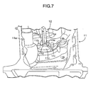
- An oil release groove extending from the sensor mounting opening to a lowest part of the bottom portion of the oil pan is formed in an upper surface of said bottom portion of the oil pan.
- the oil release groove monotonously inclines downward from the upstream end on the sensor mounting opening side to the downstream end.
- the oil release groove monotonously inclines downward from the upstream end on the sensor mounting opening side to the downstream end. Therefore, it is possible to smoothly discharge through the oil release groove the engine oil which resides in the sensor mounting opening with a foreign substance such as sludge contained therein.
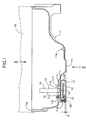
- An oil pan 11 is mounted to a bottom surface of a cylinder block 10 (see FIG. 1 ) of an engine of an automobile.
- the oil pan 11 is a vessel type member including a mounting surface 11a with respect to the cylinder block 10 at a peripheral edge of an opening of its top surface.
- An oil level sensor 12 for detecting an oil level in the oil pan 11 is provided at one end side in a longitudinal direction of the oil pan 11.
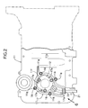
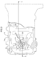
- a lowest part 11b which is the lowest in height is provided at a central portion in the longitudinal direction.
- a sensor mounting part 11c is provided at a position which is adjacent to the lowest part 11b and is raised by one step higher.
- the sensor mounting part 11c is thick as compared with the other parts of the bottom surface of the oil pan 11 including the lowest part 11b, and a circular sensor mounting opening 11d is formed in the center of the sensor mounting part 11c.
- An oil drain hole 11e for draining the engine oil in the oil pan 11 is formed in the vicinity of the side opposite from the sensor mounting part 11c with the lowest part 11b therebetween.
- an annular rib 11f is projectingly provided so as to surround a periphery of the sensor mounting opening 11d, and bosses 11g are formed at four spots of the rib 11f.
- Three bosses 11h are projectingly provided on a top surface of the oil pan 11 to surround the periphery of the sensor mounting opening 11d.
- an oil release groove 11i having a trapezoidal section is formed to cross the thick sensor mounting part 11c which surrounds the periphery of the sensor mounting opening 11d.
- the height of an upstream end of the oil release groove 11i, which communicates with the sensor mounting opening 11d, is lower than the height of an oil hole 19a of a cover member 19 of a sensing part 14.
- the height of a downstream end of the oil release groove 11i which opens toward the lowest part 11b of the oil pan 11 is lower than the bottom of the sensor mounting opening 11d.
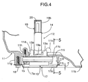
- the oil level sensor 12 includes a mounting part 13 which is formed into a hexagonal box shape in plane view, and the sensing part 14 having a shape of a tower extending upward from the center of the mounting part 13.
- the sensing part 14 In a state in which the outer peripheral surfaces of three projections 13a projectingly provided on a top surface of the mounting part 13 so as to surround the sensing part 14 are fitted in the sensor mounting opening 11d of the oil pan 11, three bolts 15 penetrating from below through the mounting part 13 are threadedly fitted into the three bosses 11h surrounding the periphery of the sensor mounting opening 11d, whereby the oil level sensor 12 is fixed to the oil pan 11.
- a seal member 16 for preventing leakage of the engine oil is sandwiched between the undersurface of the outer peripheral portion of the sensor mounting opening 11d and the top surface of the mounting part 13 of the oil level sensor 12.
- a plate-shaped cover plate 17 abuts on the lower end of the annular rib 11f projectingly provided on the undersurface of the oil pan 11, and is fixed thereto with four bolts 18 which are threadedly fitted in the four bosses 11g. Accordingly, the mounting part 13 of the oil level sensor 12 is accommodated in a recessed part 11j surrounded by the sensor mounting part 11c and the rib 11f of the oil pan 11, and is covered with the cover plate 17 from below.
- Four water draining holes 17a are formed in the cover plate 17.
- the sensing part 14 of the oil level sensor 12 includes a hollow cover member 19.
- An oil hole 19a in a slit shape laterally longer (see FIG. 4 ) for communication with the engine oil in the oil pan 11 is formed at a lower end of the cover member 19.
- An air hole 19b (see FIG. 4 ) for communication with air in the oil pan 11 is formed at an upper end of the cover member 19. Therefore, the oil level in the cover member 19 of the sensing part 14 moves up and down corresponding to the oil level in the oil pan 11.
- a plate-shaped sensing element 20 (see FIG. 4 ) is disposed inside the cover member 19 of the sensing part 14 of the oil level sensor 12.
- the sensing element 20 is energized to generate heat so that the sensing element 20 has a temperature higher by, for example, 10°C than the oil temperature, and the time elapsing before the temperature decreases by, for example, 5°C is measured.
- the oil level is high, heat radiation from the sensing element 20 to the engine oil is promoted, and the temperature drops fast.
- the oil level is low, heat radiation from the sensing element 20 to the engine oil is suppressed and the temperature slowly decreases. With this mechanism, the oil level in the oil pan 11 can be detected.
- a harness 21 (see FIG. 6 ) extending from the mounting part 13 of the oil level sensor 12 penetrates through a grommet 22 (see FIG. 6 ) which is fitted in a notch of the rib 11f of the oil pan 11, and is drawn to the outside.
- the lowest part (the undersurface of the mounting part 13) of the oil level sensor 12 is located at a position higher by a distance ⁇ with respect to the undersurface of the lowest part 11b of the oil pan 11; the mounting part 13 of the oil level sensor 12, which is exposed from the undersurface of the oil pan 11, is housed in the recessed part 11j, with its outer periphery surrounded by the rib 11f; and the undersurface of the mounting part 13 of the oil level sensor 12 is covered with the cover plate 17.
- the weight of the engine can be prevented from directly acting on the mounting part 13 of the oil level sensor 12, and at the time of colliding with a flying stone, riding on a curbstone, jacking up or the like in a state in which the engine is mounted on the vehicle body, the mounting part 13 of the oil level sensor 12 can be protected from being damaged.
- the undersurface of the lowest part 11b of the oil pan 11 and the undersurface of the cover plate 17 are at the same height and are located on the same plane, and therefore, when the engine is directly placed on the floor surface, the weight of the engine are supported by the undersurface of the lowest part 11b of the oil pan 11 and the undersurface of the cover plate 17, thereby stabilizing the posture of the engine.
- the engine oil in the oil pan 11 When the engine oil in the oil pan 11 is drained from the oil drain hole 11e for replacement, the engine oil is likely to remain inside the sensor mounting opening 11d surrounded by the thick sensor mounting part 11c. If the remaining engine oil contains a foreign substance such as sludge, the oil hole 19a of the cover member 19 of the sensing part 14 is likely to be clogged with the foreign substance.
- the oil release groove 11i is formed on the thick sensor mounting part 11c which surrounds the sensor mounting opening 11d. Therefore, the engine oil remaining inside the sensor mounting opening 11d is caused to flow out to the lowest part 11b through the oil release groove 11i, and can be discharged out of the oil pan 11 from the oil drain hole 11e formed in the vicinity of the lowest part 11b. Particularly because the oil release groove 11i monotonously inclines downward from the sensor mounting opening 11d to the lowest part 11b, the foreign substance can be effectively discharged.
- the oil level sensor 12 which detects the level of the engine oil is described, but the present invention is applicable to any other oil sensors which detect the temperature or deterioration degree of engine oil.
Landscapes
- Engineering & Computer Science (AREA)
- Physics & Mathematics (AREA)
- Mechanical Engineering (AREA)
- General Engineering & Computer Science (AREA)
- Thermal Sciences (AREA)
- Fluid Mechanics (AREA)
- General Physics & Mathematics (AREA)
- Lubrication Details And Ventilation Of Internal Combustion Engines (AREA)
- Measurement Of Levels Of Liquids Or Fluent Solid Materials (AREA)
Claims (3)
- Ölsensor-Befestigungsstruktur, umfassend eine Ölwanne (11), die unter einem Zylinderblock (10) eines Motors anzuordnen ist und Motoröl speichert, sowie einen Ölsensor (12), der einen Parameter des Motoröls erfasst und an einer Sensorbefestigungsöffnung (11d) angebracht ist, die an einem Bodenabschnitt der Ölwanne (11) vorgesehen ist, worin
der Bodenabschnitt der Ölwanne (11) ein flaches Teil (11 c), das darin die Sensorbefestigungsöffnung (11d) definiert, und ein tiefstes Teil (11 b), das niedriger angeordnet ist als das flache Teil (11 c), aufweist, dadurch gekennzeichnet, dass eine Ölablassnut (11 i), die sich von der Sensorbefestigungsöffnung (11d) zu dem tiefsten Teil (11 b) erstreckt, in einer Oberseite des Bodenabschnitts der Ölwanne (11) ausgebildet ist. - Die Ölsensor-Befestigungsstruktur nach Anspruch 1, worin die Ölablassnut (11 i) vom stromaufwärtigen Ende an der Seite der Sensorbefestigungsöffnung (11d) zum stromabwärtigen Ende hin monoton abwärts geneigt ist.
- Die Ölsensor-Befestigungsstruktur nach Anspruch 1 oder 2, worin ein Sensorbefestigungsteil (11 c) an einer Position des Bodenabschnitts der Ölwanne (11) vorgesehen ist, wobei die Position dem tiefsten Teil (11 b) benachbart ist und in Bezug auf den Letzteren um eine Stufe erhöht ist, und
das Befestigungsteil (13) des Ölsensors (12) in einem vertieften Teil (11j) der Unterseite der Ölwanne (11) aufgenommen ist, wobei das vertiefte Teil von dem Sensorbefestigungsteil (11c) und der Rippe (11f) umgeben ist.
Applications Claiming Priority (3)
| Application Number | Priority Date | Filing Date | Title |
|---|---|---|---|
| JP2005261588A JP4512015B2 (ja) | 2005-09-09 | 2005-09-09 | オイルセンサの取付構造 |
| JP2005261589A JP4573737B2 (ja) | 2005-09-09 | 2005-09-09 | オイルセンサの取付構造 |
| EP06018577A EP1762846B1 (de) | 2005-09-09 | 2006-09-05 | Öl-Sensor-Einbaustruktur |
Related Parent Applications (1)
| Application Number | Title | Priority Date | Filing Date |
|---|---|---|---|
| EP06018577.4 Division | 2006-09-05 |
Publications (2)
| Publication Number | Publication Date |
|---|---|
| EP2385368A1 EP2385368A1 (de) | 2011-11-09 |
| EP2385368B1 true EP2385368B1 (de) | 2013-10-16 |
Family
ID=37499489
Family Applications (2)
| Application Number | Title | Priority Date | Filing Date |
|---|---|---|---|
| EP11176729.9A Ceased EP2385368B1 (de) | 2005-09-09 | 2006-09-05 | Öl-Sensor-Einbaustruktur |
| EP06018577A Not-in-force EP1762846B1 (de) | 2005-09-09 | 2006-09-05 | Öl-Sensor-Einbaustruktur |
Family Applications After (1)
| Application Number | Title | Priority Date | Filing Date |
|---|---|---|---|
| EP06018577A Not-in-force EP1762846B1 (de) | 2005-09-09 | 2006-09-05 | Öl-Sensor-Einbaustruktur |
Country Status (2)
| Country | Link |
|---|---|
| US (1) | US7263964B2 (de) |
| EP (2) | EP2385368B1 (de) |
Families Citing this family (6)
| Publication number | Priority date | Publication date | Assignee | Title |
|---|---|---|---|---|
| JP4573808B2 (ja) * | 2006-06-15 | 2010-11-04 | 本田技研工業株式会社 | エンジンにおけるオイルセンサの配置構造 |
| EP2370749B1 (de) * | 2008-11-26 | 2013-07-03 | Delphi Technologies, Inc. | System zur kühlmittelleckerkennung |
| CN103742227A (zh) * | 2013-12-19 | 2014-04-23 | 重庆隆鑫发动机有限公司 | 发动机油位传感器安装构造及油位传感器 |
| US9512751B2 (en) * | 2014-09-22 | 2016-12-06 | Hyundai Motor Company | Device and method for reducing fuel dilution of diesel engine |
| JP6661984B2 (ja) * | 2015-11-12 | 2020-03-11 | いすゞ自動車株式会社 | オイルパン装置 |
| US12012879B2 (en) * | 2020-12-30 | 2024-06-18 | Hd Hyundai Infracore Co., Ltd. | Oil level sensor cover and engine comprising same |
Family Cites Families (11)
| Publication number | Priority date | Publication date | Assignee | Title |
|---|---|---|---|---|
| JPS6075709A (ja) * | 1983-09-30 | 1985-04-30 | Yamaha Motor Co Ltd | 火花点火機関の焼付き防止装置 |
| US5097703A (en) * | 1984-11-30 | 1992-03-24 | Aisin Seiki Kabushiki Kaisha | Capacitive probe for use in a system for remotely measuring the level of fluids |
| US5196824A (en) * | 1988-11-29 | 1993-03-23 | Oil Monitoring Systems, Inc. | Float actuated liquid level monitoring apparatus |
| JP2731240B2 (ja) * | 1989-05-25 | 1998-03-25 | 富士重工業株式会社 | オイルセンサ |
| US5687687A (en) * | 1995-06-07 | 1997-11-18 | Cummins Engine Company, Inc. | Oil level sensor system |
| KR200170993Y1 (ko) * | 1996-10-07 | 2000-04-01 | 정몽규 | 오일팬의 오일량 감지장치 |
| US6052896A (en) * | 1998-08-15 | 2000-04-25 | Navistar International Transportation Corp. | Method of installing an oil pan heater on an oil pan mounted on an engine block |
| US6791334B2 (en) * | 2001-02-22 | 2004-09-14 | Denso Corporation | Oil condition sensor and method for making the same |
| JP3724420B2 (ja) | 2001-07-03 | 2005-12-07 | 株式会社デンソー | オイル検出装置 |
| US20030041659A1 (en) * | 2001-09-04 | 2003-03-06 | Detroit Diesel Corporation | Electrically conductive engine oil pan sensor mounting arrangement |
| US7043983B2 (en) * | 2003-12-15 | 2006-05-16 | Fling William F | Horizontal liquid level measuring device |
-
2006
- 2006-09-05 EP EP11176729.9A patent/EP2385368B1/de not_active Ceased
- 2006-09-05 EP EP06018577A patent/EP1762846B1/de not_active Not-in-force
- 2006-09-08 US US11/517,584 patent/US7263964B2/en not_active Expired - Fee Related
Also Published As
| Publication number | Publication date |
|---|---|
| US7263964B2 (en) | 2007-09-04 |
| EP1762846B1 (de) | 2012-08-01 |
| US20070057675A1 (en) | 2007-03-15 |
| EP1762846A2 (de) | 2007-03-14 |
| EP1762846A3 (de) | 2010-06-02 |
| EP2385368A1 (de) | 2011-11-09 |
Similar Documents
| Publication | Publication Date | Title |
|---|---|---|
| US8871084B2 (en) | Fluid filter comprising a protected liquid sensor | |
| US20110041594A1 (en) | Pressure compensation unit | |
| EP1762846B1 (de) | Öl-Sensor-Einbaustruktur | |
| US20100288377A1 (en) | Pressure compensation unit for use in a pressure sensor | |
| US20120152645A1 (en) | Water drain valve comprising an umbrella diaphragm | |
| CA2651955A1 (en) | Oil sensor placement structure in engine | |
| JP4494555B2 (ja) | キャップカバー付きリザーバ | |
| EP2918800A1 (de) | Ölpfanne für einen verbrennungsmotor | |
| US20080141779A1 (en) | Air-pressure sensor for side-impact detection | |
| EP1762847B1 (de) | Ölwanne für Brennkraftmaschine | |
| EP2886399A1 (de) | Fußgängerairbag für Fahrzeug | |
| JP4512015B2 (ja) | オイルセンサの取付構造 | |
| JP4573737B2 (ja) | オイルセンサの取付構造 | |
| US4487021A (en) | Reservoir having a level detector | |
| US20070215471A1 (en) | Exhaust gas sensor | |
| EP1327534A2 (de) | Nabenkappe mit Sensorhalterung für eine Radnabenlagereinheit | |
| KR20160069720A (ko) | 차량의 냉각수 부족 감지장치 | |
| CN220248170U (zh) | 油位传感器盖及包括其的发动机 | |
| CN210400693U (zh) | 一种压力传感器组件 | |
| JPH09301152A (ja) | マスタシリンダのタンク | |
| KR100867704B1 (ko) | 덤프트럭의 덤핑 경고센서 | |
| CN115267915A (zh) | 液体传感器组件和转向系统 | |
| CN204827598U (zh) | 油位传感器的安装结构 | |
| JP2000185563A (ja) | エンジンの燃料タンク | |
| JP2005030283A (ja) | 給油口用ストレーナ |
Legal Events
| Date | Code | Title | Description |
|---|---|---|---|
| 17P | Request for examination filed |
Effective date: 20110805 |
|
| AC | Divisional application: reference to earlier application |
Ref document number: 1762846 Country of ref document: EP Kind code of ref document: P |
|
| AK | Designated contracting states |
Kind code of ref document: A1 Designated state(s): DE GB |
|
| PUAI | Public reference made under article 153(3) epc to a published international application that has entered the european phase |
Free format text: ORIGINAL CODE: 0009012 |
|
| 17Q | First examination report despatched |
Effective date: 20120816 |
|
| GRAP | Despatch of communication of intention to grant a patent |
Free format text: ORIGINAL CODE: EPIDOSNIGR1 |
|
| INTG | Intention to grant announced |
Effective date: 20130410 |
|
| GRAS | Grant fee paid |
Free format text: ORIGINAL CODE: EPIDOSNIGR3 |
|
| GRAA | (expected) grant |
Free format text: ORIGINAL CODE: 0009210 |
|
| AC | Divisional application: reference to earlier application |
Ref document number: 1762846 Country of ref document: EP Kind code of ref document: P |
|
| AK | Designated contracting states |
Kind code of ref document: B1 Designated state(s): DE GB |
|
| REG | Reference to a national code |
Ref country code: GB Ref legal event code: FG4D |
|
| REG | Reference to a national code |
Ref country code: DE Ref legal event code: R096 Ref document number: 602006038908 Country of ref document: DE Effective date: 20131212 |
|
| REG | Reference to a national code |
Ref country code: DE Ref legal event code: R097 Ref document number: 602006038908 Country of ref document: DE |
|
| PLBE | No opposition filed within time limit |
Free format text: ORIGINAL CODE: 0009261 |
|
| STAA | Information on the status of an ep patent application or granted ep patent |
Free format text: STATUS: NO OPPOSITION FILED WITHIN TIME LIMIT |
|
| 26N | No opposition filed |
Effective date: 20140717 |
|
| REG | Reference to a national code |
Ref country code: DE Ref legal event code: R097 Ref document number: 602006038908 Country of ref document: DE Effective date: 20140717 |
|
| REG | Reference to a national code |
Ref country code: DE Ref legal event code: R084 Ref document number: 602006038908 Country of ref document: DE |
|
| GBPC | Gb: european patent ceased through non-payment of renewal fee |
Effective date: 20140905 |
|
| REG | Reference to a national code |
Ref country code: DE Ref legal event code: R084 Ref document number: 602006038908 Country of ref document: DE Effective date: 20150505 |
|
| PG25 | Lapsed in a contracting state [announced via postgrant information from national office to epo] |
Ref country code: GB Free format text: LAPSE BECAUSE OF NON-PAYMENT OF DUE FEES Effective date: 20140905 |
|
| PGFP | Annual fee paid to national office [announced via postgrant information from national office to epo] |
Ref country code: DE Payment date: 20220609 Year of fee payment: 17 |
|
| REG | Reference to a national code |
Ref country code: DE Ref legal event code: R119 Ref document number: 602006038908 Country of ref document: DE |
|
| PG25 | Lapsed in a contracting state [announced via postgrant information from national office to epo] |
Ref country code: DE Free format text: LAPSE BECAUSE OF NON-PAYMENT OF DUE FEES Effective date: 20240403 |