EP2385405B9 - Vorrichtung für Panorama-Projektion, und in dieser Vorrichtung umgesetztes Verfahren - Google Patents
Vorrichtung für Panorama-Projektion, und in dieser Vorrichtung umgesetztes Verfahren Download PDFInfo
- Publication number
- EP2385405B9 EP2385405B9 EP11160401A EP11160401A EP2385405B9 EP 2385405 B9 EP2385405 B9 EP 2385405B9 EP 11160401 A EP11160401 A EP 11160401A EP 11160401 A EP11160401 A EP 11160401A EP 2385405 B9 EP2385405 B9 EP 2385405B9
- Authority
- EP
- European Patent Office
- Prior art keywords
- image
- point
- environment
- calibration
- projection
- Prior art date
- Legal status (The legal status is an assumption and is not a legal conclusion. Google has not performed a legal analysis and makes no representation as to the accuracy of the status listed.)
- Active
Links
- 238000000034 method Methods 0.000 title claims description 29
- 238000004364 calculation method Methods 0.000 claims description 53
- 239000007787 solid Substances 0.000 claims description 34
- 230000004048 modification Effects 0.000 claims description 10
- 238000012986 modification Methods 0.000 claims description 10
- 238000010276 construction Methods 0.000 claims description 8
- 238000003384 imaging method Methods 0.000 claims description 4
- 239000011159 matrix material Substances 0.000 description 22
- 229920000297 Rayon Polymers 0.000 description 21
- 239000002964 rayon Substances 0.000 description 21
- 230000003287 optical effect Effects 0.000 description 13
- 238000012937 correction Methods 0.000 description 6
- 230000006870 function Effects 0.000 description 6
- 230000009466 transformation Effects 0.000 description 6
- 230000004075 alteration Effects 0.000 description 5
- 240000008042 Zea mays Species 0.000 description 3
- 230000005540 biological transmission Effects 0.000 description 3
- 238000013459 approach Methods 0.000 description 2
- 230000008901 benefit Effects 0.000 description 2
- 238000009826 distribution Methods 0.000 description 2
- 239000000463 material Substances 0.000 description 2
- 238000005259 measurement Methods 0.000 description 2
- 230000007935 neutral effect Effects 0.000 description 2
- 238000005457 optimization Methods 0.000 description 2
- 230000008447 perception Effects 0.000 description 2
- 238000003860 storage Methods 0.000 description 2
- 241000861223 Issus Species 0.000 description 1
- 241001080024 Telles Species 0.000 description 1
- 230000008859 change Effects 0.000 description 1
- 239000003086 colorant Substances 0.000 description 1
- 238000004737 colorimetric analysis Methods 0.000 description 1
- 238000005520 cutting process Methods 0.000 description 1
- 230000000694 effects Effects 0.000 description 1
- 230000003993 interaction Effects 0.000 description 1
- 230000002093 peripheral effect Effects 0.000 description 1
- 230000000644 propagated effect Effects 0.000 description 1
- 238000011084 recovery Methods 0.000 description 1
- 238000000844 transformation Methods 0.000 description 1
- 238000002604 ultrasonography Methods 0.000 description 1
Images
Classifications
-
- G—PHYSICS
- G02—OPTICS
- G02B—OPTICAL ELEMENTS, SYSTEMS OR APPARATUS
- G02B17/00—Systems with reflecting surfaces, with or without refracting elements
- G02B17/02—Catoptric systems, e.g. image erecting and reversing system
- G02B17/06—Catoptric systems, e.g. image erecting and reversing system using mirrors only, i.e. having only one curved mirror
- G02B17/0647—Catoptric systems, e.g. image erecting and reversing system using mirrors only, i.e. having only one curved mirror using more than three curved mirrors
- G02B17/0652—Catoptric systems, e.g. image erecting and reversing system using mirrors only, i.e. having only one curved mirror using more than three curved mirrors on-axis systems with at least one of the mirrors having a central aperture
-
- G—PHYSICS
- G03—PHOTOGRAPHY; CINEMATOGRAPHY; ANALOGOUS TECHNIQUES USING WAVES OTHER THAN OPTICAL WAVES; ELECTROGRAPHY; HOLOGRAPHY
- G03B—APPARATUS OR ARRANGEMENTS FOR TAKING PHOTOGRAPHS OR FOR PROJECTING OR VIEWING THEM; APPARATUS OR ARRANGEMENTS EMPLOYING ANALOGOUS TECHNIQUES USING WAVES OTHER THAN OPTICAL WAVES; ACCESSORIES THEREFOR
- G03B21/00—Projectors or projection-type viewers; Accessories therefor
- G03B21/14—Details
- G03B21/28—Reflectors in projection beam
-
- G—PHYSICS
- G03—PHOTOGRAPHY; CINEMATOGRAPHY; ANALOGOUS TECHNIQUES USING WAVES OTHER THAN OPTICAL WAVES; ELECTROGRAPHY; HOLOGRAPHY
- G03B—APPARATUS OR ARRANGEMENTS FOR TAKING PHOTOGRAPHS OR FOR PROJECTING OR VIEWING THEM; APPARATUS OR ARRANGEMENTS EMPLOYING ANALOGOUS TECHNIQUES USING WAVES OTHER THAN OPTICAL WAVES; ACCESSORIES THEREFOR
- G03B37/00—Panoramic or wide-screen photography; Photographing extended surfaces, e.g. for surveying; Photographing internal surfaces, e.g. of pipe
- G03B37/04—Panoramic or wide-screen photography; Photographing extended surfaces, e.g. for surveying; Photographing internal surfaces, e.g. of pipe with cameras or projectors providing touching or overlapping fields of view
-
- G—PHYSICS
- G03—PHOTOGRAPHY; CINEMATOGRAPHY; ANALOGOUS TECHNIQUES USING WAVES OTHER THAN OPTICAL WAVES; ELECTROGRAPHY; HOLOGRAPHY
- G03B—APPARATUS OR ARRANGEMENTS FOR TAKING PHOTOGRAPHS OR FOR PROJECTING OR VIEWING THEM; APPARATUS OR ARRANGEMENTS EMPLOYING ANALOGOUS TECHNIQUES USING WAVES OTHER THAN OPTICAL WAVES; ACCESSORIES THEREFOR
- G03B37/00—Panoramic or wide-screen photography; Photographing extended surfaces, e.g. for surveying; Photographing internal surfaces, e.g. of pipe
- G03B37/06—Panoramic or wide-screen photography; Photographing extended surfaces, e.g. for surveying; Photographing internal surfaces, e.g. of pipe involving anamorphosis
Definitions
- the present invention relates to a device for projecting an image, for example on the surfaces of a room. It also relates to a method implemented in this device.
- the field of the invention is more particularly that of video projectors for virtual or mixed reality applications.
- the device allows for example a user to project an image on the surfaces of a room, so that the projected image creates a virtual reality environment, an observer observing the image. projected image having the illusion of viewing a scene from a virtual point of view.
- the device according to the invention makes it possible, for example, for a user to project an image onto the surfaces of a room, so that the projected image creates a mixed reality environment by combining with real elements. of the room.
- the publication GB 2,298,497 discloses a projection device comprising a projector for projecting a mother image, and a mirror for reflecting said mother image on a flat screen.
- Examples of projection device of a sequence of images on a volume are known, this device comprising a single projector.
- the projector is arranged to project an image in a projection direction, the projected image growing as it propagates at a solid projection angle centered on the projection direction.
- the volume in which the device can project the image is limited by the opening of the projector, that is to say by the value of the solid projection angle.
- Projection devices are also known comprising several projectors, each projector illuminating a facet or a particular object of the volume. These devices have the disadvantage of including several projectors, which represents an additional cost, and which generally requires coordinating the projections of the projectors.
- the object of the present invention is to provide a device for projecting an image from a single projector, without the volume or environment on which the image can be projected is limited by an opening of the projector.
- the mirror is convex because it includes a convex surface arranged to reflect at least part of the mother image and project it on the environment.
- the projector is arranged to successively project different mother images, such as for example successive mother images of a video stream.
- different mother images can have different sizes, and different positions relative to the projection axis.
- the mirror may be a convex mirror having substantially a symmetry of revolution about an axis of revolution.
- the axis of revolution of the mirror and the projection axis are preferably substantially merged.
- the mirror is arranged to reflect the mother image by deforming the mother image.
- the projector can be arranged to project the mother image at a first solid angle, and the mirror may be arranged to project the mother image at a second solid angle greater than the first solid angle.
- the first solid angle is less than 2 ⁇ steradians, that is to say, a half-sphere.
- the mother image is projected in a solid angle if the size of this mother image increases according to this solid angle as it propagates along a projection direction.
- the second solid angle can have any value between 0 and 4 ⁇ steradians, the value of the second solid angle depending in particular on the position of the mother image with respect to the axis of projection, the incidence of the axis projection on the mirror, and the size of the mother image.
- the second solid angle may be greater than 2 ⁇ steradians (ie a half-sphere), or even substantially equal to or slightly less than 4 ⁇ steradians (ie a sphere ).
- the mirror can be arranged to project the mother image in an angle around the projection axis, the value of this angle can be between 0 degrees and 360 degrees, and depending in particular on the position of the image relative to the projection axis, the incidence of the projection axis on the mirror, and the size of the mother image.
- the mirror may be arranged to project the mother image in an angle greater than 180 degrees about the projection axis, or even substantially equal to 360 degrees around the projection axis.
- an angle about an axis is defined in a plane perpendicular to that axis.
- the device according to the invention further comprises means for acquiring at least one image of the three-dimensional environment.
- An image of the environment can image part or all of the three-dimensional environment.
- the acquisition means may be arranged to acquire at least one image of the environment from light rays emitted by the environment and not reflected by the mirror.
- the acquisition means may comprise a camera, and means for rotating the camera about an axis of rotation.
- the acquisition means are arranged to acquire several images of the environment, the sum of these images imagining the environment at 360 degrees around an axis such as the axis of rotation.
- the projection axis and the axis of rotation are substantially merged.
- the device according to the invention further comprises means for modeling the three-dimensional environment from at least one image of the environment.
- the device according to the invention further comprises means for constructing the mother image as a function of an observer's position and of a three-dimensional environment modeling, so that the observer observing from his position a projection of the mother image on the environment observes a scene from a given virtual point of view.
- the device according to the invention may further comprise means for measuring at least one radiometric characteristic of the three-dimensional environment, and means for correcting the mother image as a function of at least one measured radiometric characteristic.
- the device according to the invention may further comprise means for fixing the mirror to a wall, floor or ceiling.
- Part of the mother image may not be reflected by the mirror, this part of the mother image being directly projected onto the three-dimensional environment by the designer.
- the mirror reflects the mother image by deforming the mother image.
- the projector can project the mother image in a first solid angle, and the mirror can project the mother image into a second solid angle greater than the first solid angle.
- the first solid angle is less than 2 ⁇ steradians, that is to say, a half-sphere.
- the second solid angle can have any value between 0 and 4 ⁇ steradians, the value of the second solid angle depending in particular on the position of the image with respect to the projection axis, the incidence of the axis of projection on the mirror, and the size of the mother image.
- the second solid angle may be greater than 2 ⁇ steradians (that is, half a sphere), or even substantially equal to or slightly less than 4 ⁇ steradians (i.e. a sphere).
- the mirror can project the mother image in an angle around the projection axis, the value of this angle can be between 0 degrees and 360 degrees.
- the mirror can project the mother image at an angle greater than 180 degrees around the projection axis, or even substantially equal to 360 degrees around the projection axis.
- the method according to the invention further comprises an acquisition of at least one image of the three-dimensional environment.
- the modeling points can be distributed over several mother images projected successively.
- the images of the environment acquired for the modeling comprise several images of the environment, the sum of these images imaged the environment at 360 degrees around an axis such as the axis of rotation. It is thus possible to model the environment at 360 degrees around this axis.
- the trajectory calculations may depend on calculation parameters, the method according to the invention may comprise a calibration of the parameters, the mother image comprising at least one calibration point, and the acquisition of images comprising an acquisition of at least one an image of the environment for calibration.
- the calibration points can be distributed over several mother images projected successively.
- the images of the environment acquired for the calibration comprise several images of the environment, the sum of these images imaged the environment at 360 degrees around an axis such as the axis of rotation.
- Dots of the mother image can be used both as a modeling point and as a calibration point. Thus, first points of the environment, second points of the environment, and third points of the environment can be confused. Similarly, images of the environment can be acquired for both modeling and calibration.
- a "dot” may have a surface other than zero.
- a "point" of the mother image (such as a modeling or calibration point) can typically consist of at least one pixel, preferably a single pixel.
- the size of a point of the environment and the size of a point of an image of the environment depend, for example, on the optical characteristics of the projector or the camera (focal lengths, etc.), the distance between the projector and the point of the environment, etc ...
- distance between two trajectories is understood to mean the length of the shortest straight path between the two trajectories.
- the method according to the invention further comprises a construction of the mother image according to a position of an observer, and a modeling of the three-dimensional environment, so that the observer observing from his position the projection of the mother image on the environment observes a scene from a given virtual point of view.
- the method according to the invention may further comprise a measurement of at least one radiometric characteristic of the three-dimensional environment, and a correction of the mother image as a function of the at least one measured radiometric characteristic.
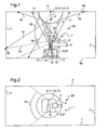
- the device 1 comprises a projector 2, a convex mirror 3, a camera 4, and means 5 for rotating the camera 4 about an axis of rotation 6.
- the device 1 is surrounded by a three-dimensional environment comprising different elements serving as projection screen, in particular lateral walls 7, a floor 8a, a ceiling 8b of a room, as well as objects included in the room. Each of these elements may not be flat, such as a curved object, or a ceiling of a cellar.
- the operation of the device 1 is as follows. We initially have a scene that we want to project on the three-dimensional environment with a desired eye impression for an observer.
- the device 1 can cover practically all the space of the environment by using on the one hand the video projector 2 which projects a mother image in an angularly limited beam, and on the other hand the recovery mirror 3 placed in a ceiling and which reflects the angularly limited beam to direct it to the three-dimensional environment in a solid angle preferably as large as possible.
- the device 1 takes into account the specificities of the projection screens: position, color, reflection coefficients, interaction with each other.
- the acquisition camera 4 which records the environment illuminated by different colored or primitive geometric backgrounds emitted by a matrix of the video projector. If the camera rotates around the projector's optical transmission axis, then it will be able to inform about all objects that serve as projection screen, with parallax effects, and without shadow area.
- the information collected by the camera is processed and introduced in terms of the correction of the mother image to modify it and generate a corrected mother image that will, she, the necessary changes to a faithful reproduction of the scene on the screens, so that the observer has an impression of observing this scene with the desired eye impression.
- the projector 2 is a matrix video projector, comprising a matrix 9 of pixels on which is displayed the mother image, and further comprising a lens 10.
- the projector is arranged to project via the lens 10 the mother image along the screen.
- a projection axis 11 orthogonal to the wavefront of the projected image, the size of the mother image increasing as it is propagated along the projection axis 11 according to a first solid projection angle 18 centered on the projection axis 11 and less than 2 ⁇ steradians.
- the projector projects the mother image into a projection cone having an apex angle of 30 degrees, i.e., in a first solid angle 18 of ⁇ / 4 steradians.
- the optical axis 13 of the objective 10 substantially passes through the center of the matrix 9, and is substantially coincidental with the projection axis 11.
- the mirror 2 is fixed to the ceiling 8b, the convex surface of the mirror 3 is oriented towards the projector 2, and the objective 10 is oriented towards the mirror 3, so that the convex surface of the mirror 3 is arranged to reflect at least part the mother image projected in the first solid angle by the projector, and to project on all or part of the three-dimensional environment and in a second solid angle the part of the mother image reflected.
- the device 1 is a catadioptric projection device, because it associates the matrix video projector 2 with the convex mirror 3 for reflecting the mother image in the three-dimensional environment 7, 8a, 8b.
- the projection of the mother image comprises a projection of several light rays 14 to 17.
- the mirror 3 is arranged to reflect a portion 14 to 16 of these light rays.
- the mirror 3 is arranged to reflect some of these rays 14 towards the ground 8a, rays projected sufficiently close to the axis of projection 11 by the projector 2 being even reflected by the mirror on the projector 2.
- the mirror 3 is also arranged to reflect some of these rays 15 to the walls 7, and some of these rays 16 to the ceiling 8b.
- the mirror 3 is furthermore arranged so as not to reflect a peripheral part of the mother image, the light rays 17 coming from this part of the mother image being directly projected onto the three-dimensional environment 7, 8a, 8b by the projector 2 .
- the mirror 3 has a symmetry of revolution about an axis of revolution 12.
- the mirror 3 can for example comprise a sphere portion whose convex surface is oriented towards the projector 2.
- the axis of revolution 12 of the mirror 3 is substantially coincident with the axis of rotation 6 of the camera 4, the projection axis 11, and the optical axis 13.
- the device 1 is arranged to project the mother image in a panoramic manner around the projection axis 11.
- the mirror may for example projecting a given mother image in an angle greater than 180 degrees around the projection axis 11.
- a mother image centered on the axis of revolution 12 and thus projection 11 is reflected and projected by the mirror to 360 degrees around the axis of projection 11, that is to say all around the axis of projection.
- this mother image is reflected. and projected by the mirror 3 in an angle that can have any value less than 360 degrees around the projection axis.
- this mother image can be projected on one or all of the side walls.
- the mirror 3 is positioned relative to the projector 2 so that the first solid projection angle 18 encompasses the convex surface of the mirror 3.
- the mirror 3 is arranged to project the mother image into a second solid angle, the size of the mirror. mother image increasing as its propagation from the mirror towards the environment according to the second solid angle.
- the second solid angle is also centered on the projection axis 11.
- the second solid angle can have any value between 0 and 4 ⁇ steradians, the value of the second solid angle depending in particular on the position of the mother image with respect to the axis of revolution of the mirror or the projection axis, and the size of the mother image on the matrix 9.
- this second solid angle is typically greater than 2 ⁇ steradians.
- the second solid angle may even be slightly less than 4 ⁇ steradians, the mirror being arranged to reflect and then project the mother image of the ground 8a to the ceiling 8b.
- the mother image can be projected onto all the side walls, floor and ceiling of the room.
- the second solid angle is delimited by the parts, located between the mirror 3 and the ceiling 8b, light rays 16.
- the camera 4 and the rotation means 5 of the camera about its axis of rotation 6 make it possible to acquire images of the three-dimensional environment 7, 8a, 8b.
- the camera can be a CCD camera connected to an acquisition card, or a webcam with USB connection, or a simple digital camera with USB or wireless link (Bluetooth or WIFI).
- the rotation of the camera can be provided by a stepping motor, the transmission between the motor and a movement of the camera about its axis 6 is provided by any transmission means, for example a timing belt, and the rotation guidance of the camera is provided by a mechanical assembly, for example a large diameter bearing surrounding the projection axis 11, and allowing the light rays of the mother image projected by the projector to pass.
- the camera For a position of the camera around its axis, the camera receives directly light rays emitted by the environment and not reflected by the mirror. From these light rays 20, the camera thus acquires an image of a part of the three-dimensional environment, that is to say of a part of the walls 7, of the ground 8a, of the ceiling 8b, and of certain objects contained in the room.
- the camera 4 and the rotating means 5 form means of omnidirectional acquisition of the three-dimensional environment, these acquisition means being able to acquire images of parts of the three-dimensional environment distributed over more than 180 degrees around the projection axis 11.
- a rotation of the camera 4 360 degrees around its axis of rotation 6 to acquire images of the three-dimensional environment all around the axis of rotation 6, and therefore all around the projection axis 11.
- there may be blind spots that is to say parts of the three-dimensional environment that can not be seen by the camera, for example parts of the ground 8a hidden by the projector 2 , or parts of the ceiling 8b hidden by the mirror 3.
- the camera has a relatively wide field of view 19, typically of the order of 90 degrees and therefore a very short focal length.
- the camera is placed between the projector 2 and the mirror 3, so that the optical axis of the camera is substantially perpendicular to the projection axis 11, or is slightly inclined relative to the perpendicular to the projection axis.
- the rotating means 5 can be arranged to perform a series of successive rotations of the camera 4 360 degrees around the axis of rotation 6, and to change for each of these rotations successive the inclination of the camera relative to the perpendicular to the axis of projection 11 or rotation.
- the camera is thus arranged to perceive the three-dimensional environment.
- the device 1 further comprises calculation means 21 connected to the camera 4.
- These calculation means typically comprise means for implementing algorithms or software, such as for example a processor, a central unit of a computer, or an electronic card.
- These calculation means are arranged to take into account a perception of the three-dimensional environment by the camera 4, then to perform on the mother image different types of correction according to the perception of the three-dimensional environment.
- the computing means are arranged to model the three-dimensional environment from one or more images of the environment acquired by the camera.
- the calculation means are arranged to construct in three dimensions a modeling of the environment by triangulation between the mirror 3 and the acquisition means 4, 5.
- the calculation means are furthermore arranged to calculate, from the modeling, a distortion to be applied to the mother image according to a position of an observer 22, so that the observer observing from his position the projection of the mother image on the three-dimensional environment observes a scene from a given virtual point of view.
- the means of calculation thus make it possible to construct the mother image to give the observer the illusion of a virtual point of view.
- the camera comprises means for measuring at least one radiometric characteristic of the three-dimensional environment, such as colorimetric characteristics or reflectance functions of the three-dimensional environment.
- the calculation means are further arranged to correct the mother image as a function of the measured radiometric characteristics, so that the observer 22 observes the projection of the mother image on the environment with colorimetric renditions and desired light intensities.
- the means of calculation allow the mother image to be faithfully reproduced from the point of view of colorimetry and light intensity, taking into account, in particular, the color, texture, and reflectance of each element of the three-dimensional environment on which the image mother is projected, and also taking into account the light sources present in the three-dimensional environment.
- the mirror projects the mother image preferably in a panoramic manner, for example in an angle A greater than 180 degrees around the projection axis, or even 360 degrees around the projection axis 11 c ' that is to say on all the walls 7 of the hall.
- this angle A can have any value between zero and 360 degrees, this value depending on the size of the mother image at the level of the matrix 9, and the position of the mother image on the matrix 9.
- the figure 3 illustrates an example of mother image 23 as it is displayed on the matrix 9 of the projector 2.
- the mother image 23 is centered on the matrix 9, and is thus cut substantially in the middle by the projection axis 11.
- the light rays 17 from the pixels of this portion 24 do not meet the mirror 3 and are directly projected on the ceiling 8b.
- This part 24 of the image can be exploited or extinguished; in practice, there is a tendency to extinguish the portion 24 of the matrix that has a direct impact on the environment and to limit itself to lighting the mirror alone.
- the other part 26 of the mother image 23, located inside the line 25, is projected by the projector 2 and then reflected by the mirror 3 on the environment three-dimensional.
- the shape of the line 25 depends on the shape of the mirror 3. In the case where the convex mirror has a shape of revolution, such as a sphere portion, the closed line 25 is a circle.
- the mother image 23 is projected on the three-dimensional environment by the projector 2 in the second solid angle greater than 2 ⁇ steradians, or even substantially equal to or slightly less than 4 ⁇ steradians.
- the method further comprises constructing the mother image 23 according to a position of the observer 22, so that the observer 22 observing from its position the projection of the mother image on the environment observes a scene from a virtual point of view P.
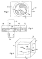
- the scene is stored in the projector 2 by storage means, in the form of six perspectives 27 to 32 illustrated on the figure 4 . All these perspectives are views of the scene from the point of view P, these perspectives being views of the scene along the six directions carried by the three axes of a three-dimensional orthogonal reference. These six perspectives are each contained in a square, so that by placing these six perspectives on the six inner faces of a cube 33 illustrated on the figure 5 , the observer placed in the center of this cube observes the scene from the point of view P. These perspectives can be photographs of a real landscape, or can be computer-generated images.
- the calculation means 21 use a modeling of the three-dimensional environment, comprising a determination of the coordinates, in the frame linked to the projector 2, of points of the environment on which the mother image is projected.
- This modeling allows, for each point or pixel of the mother image 23, a creation of a correspondence table between the coordinates (u, v) of the pixel in the mother image 23, the coordinates of the point M r of the three-dimensional environment on which this pixel is projected, and the direction of the line D connecting the point M r and the position of the observer 22, then to associate with this pixel the color and the brightness of a point M v , this point M v being a point from one of six perspectives 27 to 32 and being positioned at the intersection of the cube 33 and the right line D, the cube 33 being positioned in the environment 7, 8a, 8b so that its center, that is to say the point of view P, is substantially confused with the position of the observer 22.
- the position of the observer can be defined by default as being the position of the projector 2, or possibly any and defined by a user by input means or determined by means for locating the observer.
- the coordinates of the points of the environment on which the points of the mother image are projected are defined by a user, for example by means of input means enabling the user to define the dimensions of the image. room in which is the device 1, and for defining the position of the projector 2 and the mirror 3 in this room.
- the geometry of the environment is known by an external information source, comprising optical sensors such as laser or ultrasound.
- Calculated trajectories are simple because they consist of straight lines or straight portions in the case of geometrical optics.
- the trajectory calculations depend on calculation parameters, which will be described in more detail later.
- the calculated trajectory of the light beam 15 coming from the modeling point and the calculated trajectory of the light ray 20 coming from the first point of the environment do not intersect each other. not, but are very close to one place.
- the coordinates of the middle of the shortest segment connecting these two trajectories are considered as the coordinates of the point of intersection between these two trajectories.
- the modeling thus makes it possible, for each coordinate modeling point (u, v) on the mother image 23, and therefore by extension for each pixel of coordinates (u, v) on the mother image 23, to create the correspondence between the coordinates (u, v) of this modeling point or pixel, the coordinates of the first point of the environment 34 (or M r ) on which this modeling point or pixel is projected, and the direction of the D right connecting this modeling point 34 and the position of the observer 22. All these coordinates and directions are preferably expressed in the reference frame of the projector 2.
- the association can for example be performed by not projecting a mother image, the camera observing an image of the neutral environment, then projecting a mother image comprising a single modeling point, the camera observing another image of the image. environment corresponding to the neutral image to which is added the signal of the modeling point reflected by the mirror, projected on the environment, and re-transmitted to the camera.
- the association may for example be carried out by projecting a mother image comprising several modeling points distributed according to a particular distribution, so that an image of the environment acquired for the modeling comprises several points reproducing substantially and at least in part this distribution, each of these points of the image of the environment can then easily be associated with one of the modeling points.
- each mother image comprises only one modeling point
- the modeling comprises successive projections of mother images each having a different modeling point, the resolution of the modeling increasing with the number of projected successive mother images. .
- the images of the environment acquired for modeling are made for different angular positions adjacent to the camera.
- a single image of the environment does not necessarily image all the points of the environment on which all the modeling points are projected.
- These neighboring angular positions are preferably distributed over 360 degrees around the axis of rotation, so that two images acquired for two neighboring angular positions imitate a common part of the three-dimensional environment.
- the modelization makes it possible to model on 360 degrees around the axis of rotation 6, and thus makes it possible to model the totality of the environment three-dimensional, or almost all of the environment if there are blind spots.
- the three-dimensional coordinates of the points of the environment on which the mother image is projected can be obtained in the reference linked to the projector 2 by triangulating between the mirror 3 on one side and the camera 4 on the other.
- a knowledge of parameters of the device 1 makes it possible to calculate the equations of the trajectories of the rays coming from the mirror 3 and the equations of the trajectories of the rays picked up by the camera, and the calculation of their intersections.
- the three-dimensional environment can therefore be completely modeled, either by an unstructured cloud-like approach of modeling points, or by a mesh-type approach. This last case involves projecting modeling points in an orderly manner to know how to connect the points of the environment 34 obtained. It is also possible to analyze a cloud of points in the environment to recognize plan portions or other geometric shapes.
- trajectory calculations are simple geometrical optics calculations that depend on calculation parameters. These calculations are preferably carried out in the reference frame of the projector 2.
- the focal lengths, dimensions and resolutions of the camera and the matrix 9 may be provided by a manufacturer.
- the distortions or aberrations of the camera or lens 10 may for example be known by means of patterns.
- the method according to the invention therefore preferably comprises an optimization or calibration of the calculation parameters.
- the general principle of calibration is to project calibration points on the three-dimensional environment, having known positions in the mother image, and to deduce some of the parameters from the coordinates of the projections of the calibration points in an image acquired. by the camera for a known angular position.
- the calibration points can be distributed on the mother image in the form of a scatter plot or in the form of lines. Calibration does not at any time use the three-dimensional coordinates of the points of the environment on which the calibration points are projected, which makes it independent of the geometry of the three-dimensional environment. It is also not a matter of detecting characteristic points of the environment as do the standard stereovision calibration methods, but of using the projector 2 to create them.
- a subtracted image procedure makes it possible to increase the contrast of the device 1 in a very significant way, by avoiding the differences in materials and ambient light in the environment.
- the subtracted image procedure typically comprises subtracting, from an image acquired by the camera during the projection of a mother image including calibration points, an image acquired by the camera during projection of a mother image comprising no calibration points.
- the camera preferably comprises automatic gain control means, to remain in the range of linearity of the camera sensor avoiding saturations that penalize the subtraction.
- the calibration then comprises a projection of a mother image comprising at least one calibration point, and an acquisition of at least one image of the environment acquired for the calibration.
- these images imaged points of the environment regularly distributed in the three-dimensional environment, and by exploiting a redundancy of the points of the environment between two consecutive images.
- the calculation parameters can be optimized by minimizing the quadratic distance between the points of an image acquired by the camera and the theoretical position of the points of a successive image after rotation.
- This first type of calibration makes it possible in particular to optimize camera distortion parameters, and parameters of rigid transformation of the reference frame of the camera 4 with respect to the reference of the axis of rotation 6, such as the angle between the optical axis of the camera 4 and the axis of rotation 6.
- the number of intersections between the trajectory of the light beam projected on the third point of the environment and the trajectory of the light beam coming from the third point of the environment is maximized on all the calibration points.
- the method according to the invention may comprise a measurement of at least one radiometric characteristic of the three-dimensional environment, and a correction of the mother image as a function of at least one measured radiometric characteristic.
- the correction may include color correction or intensity of the mother image.
- the axes of rotation 6, projection 11, revolution 12 and the optical axis 13 may not be substantially merged.
- the calculations of the trajectories of the light rays emitted by the projector and the trajectories of the light rays emitted by the points of the environment are then more complex, since they must take into account significant offsets and / or inclinations between these axes, the modeling the three-dimensional environment and the construction of the mother image are consequently also more complex.
- the convex surface of the mirror 3 does not necessarily have a shape of sphere portion, this shape of sphere portion making the resolution vertical device 1 inhomogeneous. Indeed, in the device 1 just described, the more a pixel is away from the center of the matrix 9, the larger the portion of the mirror reflecting the light rays 14 to 16 emitted by this pixel, and the larger the point size. of the environment on which this ray is projected is great. A mirror profile 3 is therefore preferably used which tends to homogenize the vertical resolution of the device 1 with respect to a spherical mirror.
Landscapes
- Physics & Mathematics (AREA)
- General Physics & Mathematics (AREA)
- Optics & Photonics (AREA)
- Transforming Electric Information Into Light Information (AREA)
- Projection Apparatus (AREA)
- Image Processing (AREA)
- Medicines Containing Antibodies Or Antigens For Use As Internal Diagnostic Agents (AREA)
Claims (15)
- Projektionsverfahren, umfassend:- eine Projektion eines Hauptbildes (23) entlang einer Projektionsachse (11),- eine Reflexion wenigstens eines Teils des Hauptbildes mittels eines konvexen Spiegels (3),- eine Projektion des mittels des konvexen Spiegels reflektierten Hauptbildes auf eine dreidimensionale Umgebung (7, 8a, 8b),- eine Aufnahme wenigstens eines Bildes der dreidimensionalen Umgebung,- eine Modellierung der dreidimensionalen Umgebung anhand des wenigstens einen Bildes der dreidimensionalen Umgebung, und
dadurch gekennzeichnet, dass es ferner umfasst- eine Konstruktion des Hauptbildes in Abhängigkeit einer Position eines Betrachters (22) und der Modellierung der dreidimensionalen Umgebung, so dass der Betrachter, der von seiner Position die Projektion des Hauptbildes auf die Umgebung betrachtet, eine Szene von einem virtuellen Aussichtspunkt (P) aus betrachtet. - Verfahren nach Anspruch 1, dadurch gekennzeichnet, dass die Aufnahme eines Bildes umfasst:- ein Positionieren einer Kamera (4) in einer Winkelposition um eine Rotationsachse (6) und- eine Aufnahme eines Bildes der Umgebung für diese Winkelposition der Kamera mittels durch die dreidimensionale Umgebung ausgesandter Lichtstrahlen (20).
- Verfahren nach Anspruch 1 oder 2, dadurch gekennzeichnet, dass das Hauptbild wenigstens einen Modellierungspunkt umfasst, wobei die Bildaufnahme eine Aufnahme wenigstens eines für die Modellierung aufgenommenen Bildes der Umgebung umfasst, wobei die Modellierung für jeden Modellierungspunkt und für jedes für die Modellierung aufgenommene Bild der Umgebung umfasst:- eine Berechnung des Weges eines von dem Modellierungspunkt ausgegangenen, durch den Spiegel reflektierten und auf einen ersten Punkt der Umgebung projizierten Lichtstrahls (15),- eine Berechnung des Weges eines von dem ersten Punkt der Umgebung (34) ausgegangenen und durch einen Punkt des für die Modellierung aufgenommenen Bildes der Umgebung abgebildeten Lichtstrahls (20), sowie- eine Berechnung eines Schnittpunktes des Weges des von dem Modellierungspunkt ausgegangenen Lichtstrahls (15) und des Weges des von dem ersten Punkt der Umgebung (34) ausgegangenen Lichtstrahls (20).
- Verfahren nach Anspruch 3, dadurch gekennzeichnet, dass die Wegeberechnungen von Berechnungsparametern abhängen, dass es eine Kalibrierung der Parameter umfasst, dass das Hauptbild wenigstens einen Kalibrierungspunkt umfasst und dass die Bildaufnahme eine Aufnahme wenigstens eines für die Kalibrierung aufgenommenen Bildes der Umgebung umfasst.
- Verfahren nach Anspruch 4, dadurch gekennzeichnet, dass die für die Kalibrierung aufgenommenen Bilder der Umgebung wenigstens ein Paar von unterschiedlichen Bildern, die jedoch einen gemeinsamen Teil der Umgebung abbilden, umfassen, wobei die Kalibrierung für jeden Kalibrierungspunkt und für jedes Bilderpaar umfasst:- eine Verknüpfung des Kalibrierungspunktes mit einem Punkt des ersten Bildes des Paars und mit einem Punkt des zweiten Bildes des Paars, wobei der Punkt des ersten Bildes des Paars und der Punkt des zweiten Bildes des Paars einen zweiten Punkt der Umgebung, auf den der Kalibrierungspunkt projiziert wird, abbilden,- eine Berechnung einer theoretischen Position des Punktes des zweiten Bildes des Paars, anhand der Position des Punktes des ersten Bildes des Paars sowie der Berechnungsparameter.
- Verfahren nach Anspruch 5, dadurch gekennzeichnet, dass die Kalibrierung ferner eine Modifikation von wenigstens einem der Berechnungsparameter umfasst, um die Summe -an allen Kalibrierungspunkten- der Abstände zwischen der Position des Punktes des zweiten Bildes des Paars und der theoretischen Position dieses Punktes des zweiten Bildes des Paars zu minimieren.
- Verfahren nach einem der Ansprüche 4 bis 6, dadurch gekennzeichnet, dass die Kalibrierung für jeden Kalibrierungspunkt und für jedes für die Kalibrierung aufgenommene Bild der Umgebung umfasst:- eine Berechnung des Weges eines von dem Kalibrierungspunkt ausgegangenen, durch den Spiegel reflektierten und auf einen dritten Punkt der Umgebung projizierten Lichtstrahls,- eine Berechnung des Weges eines von dem dritten Punkt der Umgebung ausgegangenen und durch einen Punkt des für die Kalibrierung aufgenommenen Bildes der Umgebung abgebildeten Lichtstrahls.
- Verfahren nach Anspruch 7, dadurch gekennzeichnet, dass die Kalibrierung ferner eine Modifikation von wenigstens einem der Berechnungsparameter umfasst, um die Summe -an allen Kalibrierungspunkten- der Abstände zwischen dem Weg des auf den dritten Punkt der Umgebung projizierten Lichtstrahls und dem Weg des von dem dritten Punkt der Umgebung ausgegangenen Lichtstrahls zu minimieren.
- Verfahren nach einem der Ansprüche 1 bis 8, dadurch gekennzeichnet, dass die Position des Betrachters standardmäßig als die Position des Projektors (2) definiert ist.
- Verfahren nach einem der Ansprüche 1 bis 8, dadurch gekennzeichnet, dass die Position des Betrachters durch Mittel zum Lokalisieren des Betrachters bestimmt wird.
- Verfahren nach einem der vorhergehenden Ansprüche, dadurch gekennzeichnet, dass der Spiegel das Hauptbild in einen Raumwinkel projiziert, der größer als 2Π Steradiant, vorzugsweise geringfügig kleiner als 4Π Steradiant ist.
- Verfahren nach einem der vorhergehenden Ansprüche, dadurch gekennzeichnet, dass der Spiegel das Hauptbild in einem Winkel größer als 180 Grad um die Projektionsachse (11), vorzugsweise im Wesentlichen gleich 360 Grad um die Projektionsachse projiziert.
- Projektionsvorrichtung (1), umfassend:- einen Projektor (2), der angeordnet ist, um ein Hauptbild (23) entlang einer Projektionsachse (11) zu projizieren,- einen konvexen Spiegel (3), der angeordnet ist, um das Hauptbild wenigstens teilweise zu reflektieren und um es auf eine dreidimensionale Umgebung (7, 8a, 8b) zu projizieren,- Mittel (4, 5) zur Aufnahme wenigstens eines Bildes der dreidimensionalen Umgebung,- Mittel (21) zum Modellieren der dreidimensionalen Umgebung anhand wenigstens eines Bildes der Umgebung, und
dadurch gekennzeichnet, dass sie ferner umfasst:- Mittel (21) zum Konstruieren des Hauptbildes in Abhängigkeit einer Position eines Betrachters (22) und einer Modellierung der dreidimensionalen Umgebung, so dass der Betrachter, der von seiner Position eine Projektion des Hauptbildes auf die Umgebung betrachtet, eine Szene von einem virtuellen Aussichtspunkt (P) aus betrachtet. - Vorrichtung nach Anspruch 13, dadurch gekennzeichnet, dass die Aufnahmemittel angeordnet sind, um wenigstens ein Bild der Umgebung mittels durch die Umgebung ausgesandter und nicht durch den Spiegel reflektierter Lichtstrahlen (20) aufzunehmen.
- Vorrichtung nach Anspruch 13 oder 14, dadurch gekennzeichnet, dass die Aufnahmemittel eine Kamera (4) sowie Mittel zum Indrehungversetzen (5) der Kamera um eine Rotationsachse (6) umfassen.
Applications Claiming Priority (2)
| Application Number | Priority Date | Filing Date | Title |
|---|---|---|---|
| FR0705784A FR2919934B1 (fr) | 2007-08-09 | 2007-08-09 | Dispositif de projection panoramique, et procede mis en oeuvre dans ce dispositif |
| EP08827211A EP2183633A2 (de) | 2007-08-09 | 2008-08-08 | Panoramisches projektionsgerät und von diesem gerät angewandtes verfahren |
Related Parent Applications (3)
| Application Number | Title | Priority Date | Filing Date |
|---|---|---|---|
| WOPCT/FR2008/051485 Previously-Filed-Application | 2008-08-08 | ||
| WOPCT/FR20/08051485 Previously-Filed-Application | 2008-08-08 | ||
| EP08827211.7 Division | 2008-08-08 |
Publications (4)
| Publication Number | Publication Date |
|---|---|
| EP2385405A1 EP2385405A1 (de) | 2011-11-09 |
| EP2385405B1 EP2385405B1 (de) | 2012-08-29 |
| EP2385405B9 true EP2385405B9 (de) | 2012-12-19 |
| EP2385405B8 EP2385405B8 (de) | 2013-01-09 |
Family
ID=38988005
Family Applications (2)
| Application Number | Title | Priority Date | Filing Date |
|---|---|---|---|
| EP08827211A Withdrawn EP2183633A2 (de) | 2007-08-09 | 2008-08-08 | Panoramisches projektionsgerät und von diesem gerät angewandtes verfahren |
| EP11160401A Active EP2385405B8 (de) | 2007-08-09 | 2008-08-08 | Vorrichtung für Panorama-Projektion, und in dieser Vorrichtung umgesetztes Verfahren |
Family Applications Before (1)
| Application Number | Title | Priority Date | Filing Date |
|---|---|---|---|
| EP08827211A Withdrawn EP2183633A2 (de) | 2007-08-09 | 2008-08-08 | Panoramisches projektionsgerät und von diesem gerät angewandtes verfahren |
Country Status (8)
| Country | Link |
|---|---|
| US (1) | US8272752B2 (de) |
| EP (2) | EP2183633A2 (de) |
| JP (2) | JP2010536061A (de) |
| KR (1) | KR101319777B1 (de) |
| CA (1) | CA2695909C (de) |
| ES (1) | ES2394588T3 (de) |
| FR (1) | FR2919934B1 (de) |
| WO (1) | WO2009022087A2 (de) |
Families Citing this family (15)
| Publication number | Priority date | Publication date | Assignee | Title |
|---|---|---|---|---|
| US9649551B2 (en) | 2008-06-03 | 2017-05-16 | Tweedletech, Llc | Furniture and building structures comprising sensors for determining the position of one or more objects |
| WO2012033862A2 (en) | 2010-09-09 | 2012-03-15 | Tweedletech, Llc | A multi-dimensional game comprising interactive physical and virtual components |
| WO2009149112A1 (en) | 2008-06-03 | 2009-12-10 | Tweedletech, Llc | An intelligent game system for putting intelligence into board and tabletop games including miniatures |
| US8602857B2 (en) | 2008-06-03 | 2013-12-10 | Tweedletech, Llc | Intelligent board game system with visual marker based game object tracking and identification |
| US8974295B2 (en) * | 2008-06-03 | 2015-03-10 | Tweedletech, Llc | Intelligent game system including intelligent foldable three-dimensional terrain |
| JP5519000B2 (ja) | 2009-04-30 | 2014-06-11 | ゼルティック エステティックス インコーポレイテッド | 脂肪が豊富な皮下細胞から熱を除去するためのデバイス、システム、及び方法 |
| JP5993856B2 (ja) | 2010-09-09 | 2016-09-14 | トウィードルテック リミテッド ライアビリティ カンパニー | 動的特徴追跡を有するボードゲーム |
| US9892666B1 (en) * | 2012-06-20 | 2018-02-13 | Amazon Technologies, Inc. | Three-dimensional model generation |
| US9436068B2 (en) * | 2014-09-17 | 2016-09-06 | The Boeing Company | Portable constant resolution visual system (CRVS) with defined throw distance |
| KR102167836B1 (ko) * | 2015-09-10 | 2020-10-20 | 한국과학기술원 | 단일 프로젝터와 구형 거울 기반의 전방향 프로젝션 방법 및 시스템 |
| FR3041110B1 (fr) * | 2015-09-14 | 2018-03-16 | Valeo Vision | Procede de projection pour vehicule automobile d'une image sur une surface de projection |
| CN107517336A (zh) * | 2016-06-17 | 2017-12-26 | 深圳市合正汽车电子有限公司 | 一种摄像头 |
| US11218662B2 (en) * | 2018-02-08 | 2022-01-04 | Sony Corporation | Image processing device, image processing method, and projection system |
| CN109788180B (zh) * | 2019-02-28 | 2024-03-29 | 深圳市共进电子股份有限公司 | 一种拍摄装置以及检测设备 |
| CN115629509A (zh) * | 2021-07-14 | 2023-01-20 | 中强光电股份有限公司 | 投影设备 |
Family Cites Families (30)
| Publication number | Priority date | Publication date | Assignee | Title |
|---|---|---|---|---|
| US2299682A (en) * | 1939-10-20 | 1942-10-20 | James S Conant | Apparatus and method for taking and projecting pictures |
| FR84774E (fr) * | 1963-11-20 | 1965-04-16 | Salle de projection cinématographique | |
| US3692934A (en) * | 1971-02-11 | 1972-09-19 | Us Navy | Roll and pitch simulator utilizing 360{20 {0 display |
| US3740469A (en) * | 1972-04-19 | 1973-06-19 | Us Navy | Reflective panoramic t.v. projection system |
| FR2404243A1 (fr) * | 1977-09-21 | 1979-04-20 | Jaulmes Philippe | Procede de projection et de prise de vue pour simulateur de vol, et salle de projection permettant sa mise en oeuvre |
| US5329310A (en) * | 1992-06-30 | 1994-07-12 | The Walt Disney Company | Method and apparatus for controlling distortion of a projected image |
| GB2298497B (en) * | 1995-03-02 | 1997-05-21 | Robin Christopher Colclough | Image display device |
| US6449103B1 (en) * | 1997-04-16 | 2002-09-10 | Jeffrey R. Charles | Solid catadioptric omnidirectional optical system having central coverage means which is associated with a camera, projector, medical instrument, or similar article |
| NL1009506C2 (nl) * | 1998-06-26 | 2000-01-04 | Evolution Technology N V I O | Weergave-inrichting. |
| JP2916142B1 (ja) | 1998-08-10 | 1999-07-05 | 洋夫 岩田 | 全周球面スクリーン投影装置 |
| JP4069550B2 (ja) * | 1999-02-23 | 2008-04-02 | 松下電工株式会社 | 仮想環境体験表示装置 |
| JP3956543B2 (ja) * | 1999-07-23 | 2007-08-08 | 松下電工株式会社 | 自動補正機構付き広視野角表示装置 |
| US6669346B2 (en) * | 2000-05-15 | 2003-12-30 | Darrell J. Metcalf | Large-audience, positionable imaging and display system for exhibiting panoramic imagery, and multimedia content featuring a circularity of action |
| JP2002203237A (ja) | 2000-08-30 | 2002-07-19 | Usc Corp | 曲面像変換方法及びこの曲面像変換方法を記録した記録媒体 |
| US6409351B1 (en) * | 2001-02-12 | 2002-06-25 | Thomas R. Ligon | Spherical image projection system using a convex reflecting image dispersing element |
| US6905218B2 (en) * | 2001-04-12 | 2005-06-14 | Luc Courchesne | Panoramic and horizontally immersive image display system and method |
| US6744569B2 (en) * | 2001-06-19 | 2004-06-01 | Genex Technologies, Inc | Method and apparatus for omnidirectional three dimensional imaging |
| US6554434B2 (en) * | 2001-07-06 | 2003-04-29 | Sony Corporation | Interactive projection system |
| US7253969B2 (en) * | 2002-05-14 | 2007-08-07 | O.D.F. Medical Ltd. | Spherical and nearly spherical view imaging assembly |
| JP2003344962A (ja) * | 2002-05-24 | 2003-12-03 | Canon Inc | 全方位映像表示システム |
| US6834965B2 (en) * | 2003-03-21 | 2004-12-28 | Mitsubishi Electric Research Laboratories, Inc. | Self-configurable ad-hoc projector cluster |
| US7463280B2 (en) * | 2003-06-03 | 2008-12-09 | Steuart Iii Leonard P | Digital 3D/360 degree camera system |
| US7118228B2 (en) * | 2003-11-04 | 2006-10-10 | Hewlett-Packard Development Company, L.P. | Image display system |
| JP3921205B2 (ja) * | 2004-01-13 | 2007-05-30 | 株式会社イフ | 立体映像表示装置 |
| JP2005331813A (ja) * | 2004-05-21 | 2005-12-02 | Seiko Epson Corp | 自走投影装置 |
| GB2425363A (en) * | 2005-04-18 | 2006-10-25 | Sharp Kk | Panoramic adapter with mirrors formed by rotating conic section |
| JP4617993B2 (ja) * | 2005-04-28 | 2011-01-26 | ソニー株式会社 | 画像処理装置および画像処理方法、プログラム、並びに、記録媒体 |
| JP4650256B2 (ja) * | 2005-12-22 | 2011-03-16 | パナソニック電工株式会社 | 情報提示システム |
| US20070200926A1 (en) * | 2006-02-28 | 2007-08-30 | Chianglin Yi T | Apparatus and method for generating panorama images |
| US7604354B1 (en) * | 2006-05-10 | 2009-10-20 | Ligon Thomas R | Three-dimensional projection apparatus using coaxial optical alignment |
-
2007
- 2007-08-09 FR FR0705784A patent/FR2919934B1/fr not_active Expired - Fee Related
-
2008
- 2008-08-08 WO PCT/FR2008/051485 patent/WO2009022087A2/fr not_active Ceased
- 2008-08-08 EP EP08827211A patent/EP2183633A2/de not_active Withdrawn
- 2008-08-08 KR KR1020107005100A patent/KR101319777B1/ko not_active Expired - Fee Related
- 2008-08-08 ES ES11160401T patent/ES2394588T3/es active Active
- 2008-08-08 CA CA2695909A patent/CA2695909C/en not_active Expired - Fee Related
- 2008-08-08 JP JP2010519500A patent/JP2010536061A/ja active Pending
- 2008-08-08 EP EP11160401A patent/EP2385405B8/de active Active
- 2008-08-08 US US12/672,767 patent/US8272752B2/en not_active Expired - Fee Related
-
2013
- 2013-05-27 JP JP2013111380A patent/JP5486113B2/ja not_active Expired - Fee Related
Also Published As
| Publication number | Publication date |
|---|---|
| CA2695909C (en) | 2014-04-01 |
| FR2919934A1 (fr) | 2009-02-13 |
| EP2183633A2 (de) | 2010-05-12 |
| US20110211175A1 (en) | 2011-09-01 |
| US8272752B2 (en) | 2012-09-25 |
| EP2385405A1 (de) | 2011-11-09 |
| JP2013210663A (ja) | 2013-10-10 |
| WO2009022087A2 (fr) | 2009-02-19 |
| JP5486113B2 (ja) | 2014-05-07 |
| KR20100081971A (ko) | 2010-07-15 |
| ES2394588T3 (es) | 2013-02-04 |
| WO2009022087A3 (fr) | 2009-06-25 |
| EP2385405B1 (de) | 2012-08-29 |
| EP2385405B8 (de) | 2013-01-09 |
| JP2010536061A (ja) | 2010-11-25 |
| KR101319777B1 (ko) | 2013-10-17 |
| CA2695909A1 (en) | 2009-02-19 |
| FR2919934B1 (fr) | 2010-09-17 |
| HK1163824A1 (en) | 2012-09-14 |
Similar Documents
| Publication | Publication Date | Title |
|---|---|---|
| EP2385405B1 (de) | Vorrichtung für Panorama-Projektion, und in dieser Vorrichtung umgesetztes Verfahren | |
| EP1362255B1 (de) | Haltevorrichtung für eine fotokamera | |
| EP1989582B1 (de) | Verfahren und einrichtung zum identifizieren und kalibrieren panoramischer optischer systeme | |
| FR2821172A1 (fr) | Procede et dispositif pour l'orientation d'une image panoramique numerique | |
| EP2119226A2 (de) | Vorrichtung und verfahren zur echtzeitbeobachtung mit erweiterter realität | |
| CA2856464A1 (fr) | Systeme de tournage de film video | |
| EP3596533B1 (de) | Vorrichtung zur entmaterialisierten luftprojektion eines digitalen bildes oder einer sequenz digitaler bilder, insbesondere eines autostereoskopischen bildes oder einer sequenz von autostereoskopischen bildern | |
| FR2986337A1 (fr) | Systeme optique destine a mesurer la brdf, bsdf et bdtf | |
| WO2009040368A1 (fr) | Système et méthode d'acquisition de caractéristiques tridimensionnelles d'un objet à partir d'images prises par une pluralité d'organes de mesure | |
| FR2821156A1 (fr) | Procede et dispositif pour l'obtention d'une image panoramique numerique a teinte constante | |
| EP2994813B1 (de) | Verfahren zur steuerung einer grafischen schnittstelle zur anzeige von bildern eines dreidimensionalen objekts | |
| WO2014199085A1 (fr) | Systemes de reperage de la position de la camera de tournage pour le tournage de films video | |
| WO2010072912A1 (fr) | Dispositif de numerisation tridimensionnelle a reconstruction dense | |
| CA3057337A1 (fr) | Procede de texturation d'un modele 3d | |
| EP1702472A2 (de) | Verfahren und system zur bestimmung der verschiebung eines pixels und aufzeichnungsmedium dafür | |
| WO2025017261A1 (fr) | Procédé pour la calibration de l'affichage d'images dans un casque de réalité mixte | |
| FR3162544A1 (fr) | Procédé et dispositif de caractérisation d’un terminal comportant une source lumineuse et au moins une caméra | |
| HK1163824B (en) | Panomaric projection device and method implemented by said device | |
| FR3030843A1 (fr) | Procede de projection d'images sur une scene tridimensionnelle hybride | |
| FR3043295A1 (fr) | Dispositif de realite augmentee spatiale pour un environnement de bureau |
Legal Events
| Date | Code | Title | Description |
|---|---|---|---|
| AC | Divisional application: reference to earlier application |
Ref document number: 2183633 Country of ref document: EP Kind code of ref document: P |
|
| AK | Designated contracting states |
Kind code of ref document: A1 Designated state(s): AT BE BG CH CY CZ DE DK EE ES FI FR GB GR HR HU IE IS IT LI LT LU LV MC MT NL NO PL PT RO SE SI SK TR |
|
| AX | Request for extension of the european patent |
Extension state: AL BA MK RS |
|
| PUAI | Public reference made under article 153(3) epc to a published international application that has entered the european phase |
Free format text: ORIGINAL CODE: 0009012 |
|
| 17P | Request for examination filed |
Effective date: 20120209 |
|
| GRAP | Despatch of communication of intention to grant a patent |
Free format text: ORIGINAL CODE: EPIDOSNIGR1 |
|
| GRAS | Grant fee paid |
Free format text: ORIGINAL CODE: EPIDOSNIGR3 |
|
| GRAA | (expected) grant |
Free format text: ORIGINAL CODE: 0009210 |
|
| AC | Divisional application: reference to earlier application |
Ref document number: 2183633 Country of ref document: EP Kind code of ref document: P |
|
| AK | Designated contracting states |
Kind code of ref document: B1 Designated state(s): AT BE BG CH CY CZ DE DK EE ES FI FR GB GR HR HU IE IS IT LI LT LU LV MC MT NL NO PL PT RO SE SI SK TR |
|
| AX | Request for extension of the european patent |
Extension state: AL BA MK RS |
|
| REG | Reference to a national code |
Ref country code: GB Ref legal event code: FG4D Free format text: NOT ENGLISH |
|
| REG | Reference to a national code |
Ref country code: CH Ref legal event code: EP |
|
| REG | Reference to a national code |
Ref country code: HK Ref legal event code: DE Ref document number: 1163824 Country of ref document: HK |
|
| REG | Reference to a national code |
Ref country code: AT Ref legal event code: REF Ref document number: 573352 Country of ref document: AT Kind code of ref document: T Effective date: 20120915 |
|
| REG | Reference to a national code |
Ref country code: IE Ref legal event code: FG4D Free format text: LANGUAGE OF EP DOCUMENT: FRENCH |
|
| REG | Reference to a national code |
Ref country code: DE Ref legal event code: R096 Ref document number: 602008018502 Country of ref document: DE Effective date: 20121025 |
|
| REG | Reference to a national code |
Ref country code: NL Ref legal event code: T3 |
|
| REG | Reference to a national code |
Ref country code: SE Ref legal event code: TRGR |
|
| REG | Reference to a national code |
Ref country code: AT Ref legal event code: MK05 Ref document number: 573352 Country of ref document: AT Kind code of ref document: T Effective date: 20120829 |
|
| REG | Reference to a national code |
Ref country code: LT Ref legal event code: MG4D Effective date: 20120822 |
|
| PG25 | Lapsed in a contracting state [announced via postgrant information from national office to epo] |
Ref country code: LT Free format text: LAPSE BECAUSE OF FAILURE TO SUBMIT A TRANSLATION OF THE DESCRIPTION OR TO PAY THE FEE WITHIN THE PRESCRIBED TIME-LIMIT Effective date: 20120829 Ref country code: AT Free format text: LAPSE BECAUSE OF FAILURE TO SUBMIT A TRANSLATION OF THE DESCRIPTION OR TO PAY THE FEE WITHIN THE PRESCRIBED TIME-LIMIT Effective date: 20120829 Ref country code: IS Free format text: LAPSE BECAUSE OF FAILURE TO SUBMIT A TRANSLATION OF THE DESCRIPTION OR TO PAY THE FEE WITHIN THE PRESCRIBED TIME-LIMIT Effective date: 20121229 Ref country code: HR Free format text: LAPSE BECAUSE OF FAILURE TO SUBMIT A TRANSLATION OF THE DESCRIPTION OR TO PAY THE FEE WITHIN THE PRESCRIBED TIME-LIMIT Effective date: 20120829 Ref country code: NO Free format text: LAPSE BECAUSE OF FAILURE TO SUBMIT A TRANSLATION OF THE DESCRIPTION OR TO PAY THE FEE WITHIN THE PRESCRIBED TIME-LIMIT Effective date: 20121129 |
|
| REG | Reference to a national code |
Ref country code: CH Ref legal event code: NV Representative=s name: RENTSCH PARTNER AG, CH |
|
| REG | Reference to a national code |
Ref country code: ES Ref legal event code: FG2A Ref document number: 2394588 Country of ref document: ES Kind code of ref document: T3 Effective date: 20130204 |
|
| REG | Reference to a national code |
Ref country code: HK Ref legal event code: GR Ref document number: 1163824 Country of ref document: HK |
|
| REG | Reference to a national code |
Ref country code: CH Ref legal event code: NV Representative=s name: RENTSCH PARTNER AG, CH |
|
| PG25 | Lapsed in a contracting state [announced via postgrant information from national office to epo] |
Ref country code: PT Free format text: LAPSE BECAUSE OF FAILURE TO SUBMIT A TRANSLATION OF THE DESCRIPTION OR TO PAY THE FEE WITHIN THE PRESCRIBED TIME-LIMIT Effective date: 20121231 Ref country code: SI Free format text: LAPSE BECAUSE OF FAILURE TO SUBMIT A TRANSLATION OF THE DESCRIPTION OR TO PAY THE FEE WITHIN THE PRESCRIBED TIME-LIMIT Effective date: 20120829 Ref country code: LV Free format text: LAPSE BECAUSE OF FAILURE TO SUBMIT A TRANSLATION OF THE DESCRIPTION OR TO PAY THE FEE WITHIN THE PRESCRIBED TIME-LIMIT Effective date: 20120829 Ref country code: GR Free format text: LAPSE BECAUSE OF FAILURE TO SUBMIT A TRANSLATION OF THE DESCRIPTION OR TO PAY THE FEE WITHIN THE PRESCRIBED TIME-LIMIT Effective date: 20121130 |
|
| PG25 | Lapsed in a contracting state [announced via postgrant information from national office to epo] |
Ref country code: RO Free format text: LAPSE BECAUSE OF FAILURE TO SUBMIT A TRANSLATION OF THE DESCRIPTION OR TO PAY THE FEE WITHIN THE PRESCRIBED TIME-LIMIT Effective date: 20120829 Ref country code: CZ Free format text: LAPSE BECAUSE OF FAILURE TO SUBMIT A TRANSLATION OF THE DESCRIPTION OR TO PAY THE FEE WITHIN THE PRESCRIBED TIME-LIMIT Effective date: 20120829 Ref country code: EE Free format text: LAPSE BECAUSE OF FAILURE TO SUBMIT A TRANSLATION OF THE DESCRIPTION OR TO PAY THE FEE WITHIN THE PRESCRIBED TIME-LIMIT Effective date: 20120829 Ref country code: DK Free format text: LAPSE BECAUSE OF FAILURE TO SUBMIT A TRANSLATION OF THE DESCRIPTION OR TO PAY THE FEE WITHIN THE PRESCRIBED TIME-LIMIT Effective date: 20120829 |
|
| PG25 | Lapsed in a contracting state [announced via postgrant information from national office to epo] |
Ref country code: SK Free format text: LAPSE BECAUSE OF FAILURE TO SUBMIT A TRANSLATION OF THE DESCRIPTION OR TO PAY THE FEE WITHIN THE PRESCRIBED TIME-LIMIT Effective date: 20120829 Ref country code: PL Free format text: LAPSE BECAUSE OF FAILURE TO SUBMIT A TRANSLATION OF THE DESCRIPTION OR TO PAY THE FEE WITHIN THE PRESCRIBED TIME-LIMIT Effective date: 20120829 |
|
| PLBE | No opposition filed within time limit |
Free format text: ORIGINAL CODE: 0009261 |
|
| STAA | Information on the status of an ep patent application or granted ep patent |
Free format text: STATUS: NO OPPOSITION FILED WITHIN TIME LIMIT |
|
| PG25 | Lapsed in a contracting state [announced via postgrant information from national office to epo] |
Ref country code: BG Free format text: LAPSE BECAUSE OF FAILURE TO SUBMIT A TRANSLATION OF THE DESCRIPTION OR TO PAY THE FEE WITHIN THE PRESCRIBED TIME-LIMIT Effective date: 20121129 |
|
| 26N | No opposition filed |
Effective date: 20130530 |
|
| REG | Reference to a national code |
Ref country code: DE Ref legal event code: R097 Ref document number: 602008018502 Country of ref document: DE Effective date: 20130530 |
|
| PG25 | Lapsed in a contracting state [announced via postgrant information from national office to epo] |
Ref country code: CY Free format text: LAPSE BECAUSE OF FAILURE TO SUBMIT A TRANSLATION OF THE DESCRIPTION OR TO PAY THE FEE WITHIN THE PRESCRIBED TIME-LIMIT Effective date: 20120829 |
|
| PG25 | Lapsed in a contracting state [announced via postgrant information from national office to epo] |
Ref country code: MC Free format text: LAPSE BECAUSE OF FAILURE TO SUBMIT A TRANSLATION OF THE DESCRIPTION OR TO PAY THE FEE WITHIN THE PRESCRIBED TIME-LIMIT Effective date: 20120829 |
|
| PGFP | Annual fee paid to national office [announced via postgrant information from national office to epo] |
Ref country code: LU Payment date: 20140822 Year of fee payment: 7 |
|
| PGFP | Annual fee paid to national office [announced via postgrant information from national office to epo] |
Ref country code: FI Payment date: 20140813 Year of fee payment: 7 Ref country code: NL Payment date: 20140820 Year of fee payment: 7 Ref country code: IE Payment date: 20140828 Year of fee payment: 7 Ref country code: CH Payment date: 20140820 Year of fee payment: 7 |
|
| PGFP | Annual fee paid to national office [announced via postgrant information from national office to epo] |
Ref country code: ES Payment date: 20140826 Year of fee payment: 7 Ref country code: FR Payment date: 20140826 Year of fee payment: 7 Ref country code: GB Payment date: 20140822 Year of fee payment: 7 Ref country code: SE Payment date: 20140820 Year of fee payment: 7 |
|
| PGFP | Annual fee paid to national office [announced via postgrant information from national office to epo] |
Ref country code: IT Payment date: 20140822 Year of fee payment: 7 |
|
| PGFP | Annual fee paid to national office [announced via postgrant information from national office to epo] |
Ref country code: BE Payment date: 20140820 Year of fee payment: 7 Ref country code: DE Payment date: 20140930 Year of fee payment: 7 |
|
| PG25 | Lapsed in a contracting state [announced via postgrant information from national office to epo] |
Ref country code: TR Free format text: LAPSE BECAUSE OF FAILURE TO SUBMIT A TRANSLATION OF THE DESCRIPTION OR TO PAY THE FEE WITHIN THE PRESCRIBED TIME-LIMIT Effective date: 20120829 Ref country code: MT Free format text: LAPSE BECAUSE OF FAILURE TO SUBMIT A TRANSLATION OF THE DESCRIPTION OR TO PAY THE FEE WITHIN THE PRESCRIBED TIME-LIMIT Effective date: 20120829 |
|
| PG25 | Lapsed in a contracting state [announced via postgrant information from national office to epo] |
Ref country code: HU Free format text: LAPSE BECAUSE OF FAILURE TO SUBMIT A TRANSLATION OF THE DESCRIPTION OR TO PAY THE FEE WITHIN THE PRESCRIBED TIME-LIMIT; INVALID AB INITIO Effective date: 20080808 |
|
| REG | Reference to a national code |
Ref country code: DE Ref legal event code: R119 Ref document number: 602008018502 Country of ref document: DE |
|
| REG | Reference to a national code |
Ref country code: SE Ref legal event code: EUG |
|
| PG25 | Lapsed in a contracting state [announced via postgrant information from national office to epo] |
Ref country code: LU Free format text: LAPSE BECAUSE OF NON-PAYMENT OF DUE FEES Effective date: 20150808 |
|
| REG | Reference to a national code |
Ref country code: CH Ref legal event code: PL |
|
| GBPC | Gb: european patent ceased through non-payment of renewal fee |
Effective date: 20150808 |
|
| PG25 | Lapsed in a contracting state [announced via postgrant information from national office to epo] |
Ref country code: LI Free format text: LAPSE BECAUSE OF NON-PAYMENT OF DUE FEES Effective date: 20150831 Ref country code: IT Free format text: LAPSE BECAUSE OF NON-PAYMENT OF DUE FEES Effective date: 20150808 Ref country code: CH Free format text: LAPSE BECAUSE OF NON-PAYMENT OF DUE FEES Effective date: 20150831 |
|
| REG | Reference to a national code |
Ref country code: NL Ref legal event code: MM Effective date: 20150901 |
|
| PG25 | Lapsed in a contracting state [announced via postgrant information from national office to epo] |
Ref country code: SE Free format text: LAPSE BECAUSE OF NON-PAYMENT OF DUE FEES Effective date: 20150809 Ref country code: FI Free format text: LAPSE BECAUSE OF NON-PAYMENT OF DUE FEES Effective date: 20150808 |
|
| REG | Reference to a national code |
Ref country code: IE Ref legal event code: MM4A |
|
| REG | Reference to a national code |
Ref country code: FR Ref legal event code: ST Effective date: 20160429 |
|
| PG25 | Lapsed in a contracting state [announced via postgrant information from national office to epo] |
Ref country code: NL Free format text: LAPSE BECAUSE OF NON-PAYMENT OF DUE FEES Effective date: 20150901 |
|
| PG25 | Lapsed in a contracting state [announced via postgrant information from national office to epo] |
Ref country code: GB Free format text: LAPSE BECAUSE OF NON-PAYMENT OF DUE FEES Effective date: 20150808 Ref country code: DE Free format text: LAPSE BECAUSE OF NON-PAYMENT OF DUE FEES Effective date: 20160301 Ref country code: IE Free format text: LAPSE BECAUSE OF NON-PAYMENT OF DUE FEES Effective date: 20150808 |
|
| PG25 | Lapsed in a contracting state [announced via postgrant information from national office to epo] |
Ref country code: FR Free format text: LAPSE BECAUSE OF NON-PAYMENT OF DUE FEES Effective date: 20150831 |
|
| REG | Reference to a national code |
Ref country code: ES Ref legal event code: FD2A Effective date: 20160927 |
|
| PG25 | Lapsed in a contracting state [announced via postgrant information from national office to epo] |
Ref country code: ES Free format text: LAPSE BECAUSE OF NON-PAYMENT OF DUE FEES Effective date: 20150809 |
|
| PG25 | Lapsed in a contracting state [announced via postgrant information from national office to epo] |
Ref country code: BE Free format text: LAPSE BECAUSE OF NON-PAYMENT OF DUE FEES Effective date: 20150831 |