EP2385657A2 - Methods for monitoring and reporting MTC events - Google Patents
Methods for monitoring and reporting MTC events Download PDFInfo
- Publication number
- EP2385657A2 EP2385657A2 EP11003609A EP11003609A EP2385657A2 EP 2385657 A2 EP2385657 A2 EP 2385657A2 EP 11003609 A EP11003609 A EP 11003609A EP 11003609 A EP11003609 A EP 11003609A EP 2385657 A2 EP2385657 A2 EP 2385657A2
- Authority
- EP
- European Patent Office
- Prior art keywords
- mtc
- event
- mtc event
- network server
- server
- Prior art date
- Legal status (The legal status is an assumption and is not a legal conclusion. Google has not performed a legal analysis and makes no representation as to the accuracy of the status listed.)
- Withdrawn
Links
- 238000000034 method Methods 0.000 title claims abstract description 57
- 238000012544 monitoring process Methods 0.000 title claims abstract description 45
- 238000001514 detection method Methods 0.000 claims abstract description 33
- 230000035945 sensitivity Effects 0.000 claims abstract description 25
- 230000005540 biological transmission Effects 0.000 claims description 29
- 230000004044 response Effects 0.000 claims description 20
- 238000004891 communication Methods 0.000 claims description 10
- 239000008186 active pharmaceutical agent Substances 0.000 description 36
- 230000006399 behavior Effects 0.000 description 5
- 230000008859 change Effects 0.000 description 5
- 230000000875 corresponding effect Effects 0.000 description 5
- 230000009471 action Effects 0.000 description 4
- 230000000977 initiatory effect Effects 0.000 description 3
- 230000002596 correlated effect Effects 0.000 description 2
- 238000010586 diagram Methods 0.000 description 2
- 230000006870 function Effects 0.000 description 2
- 238000010295 mobile communication Methods 0.000 description 2
- 238000012986 modification Methods 0.000 description 2
- 230000004048 modification Effects 0.000 description 2
- 230000001960 triggered effect Effects 0.000 description 2
- 230000003247 decreasing effect Effects 0.000 description 1
- 230000003993 interaction Effects 0.000 description 1
- 230000007774 longterm Effects 0.000 description 1
- 238000012545 processing Methods 0.000 description 1
- 238000013139 quantization Methods 0.000 description 1
- 230000009467 reduction Effects 0.000 description 1
- 230000011664 signaling Effects 0.000 description 1
Images


Classifications
-
- H—ELECTRICITY
- H04—ELECTRIC COMMUNICATION TECHNIQUE
- H04L—TRANSMISSION OF DIGITAL INFORMATION, e.g. TELEGRAPHIC COMMUNICATION
- H04L43/00—Arrangements for monitoring or testing data switching networks
- H04L43/16—Threshold monitoring
-
- H—ELECTRICITY
- H04—ELECTRIC COMMUNICATION TECHNIQUE
- H04L—TRANSMISSION OF DIGITAL INFORMATION, e.g. TELEGRAPHIC COMMUNICATION
- H04L41/00—Arrangements for maintenance, administration or management of data switching networks, e.g. of packet switching networks
- H04L41/06—Management of faults, events, alarms or notifications
- H04L41/0681—Configuration of triggering conditions
-
- H—ELECTRICITY
- H04—ELECTRIC COMMUNICATION TECHNIQUE
- H04W—WIRELESS COMMUNICATION NETWORKS
- H04W4/00—Services specially adapted for wireless communication networks; Facilities therefor
-
- H—ELECTRICITY
- H04—ELECTRIC COMMUNICATION TECHNIQUE
- H04W—WIRELESS COMMUNICATION NETWORKS
- H04W4/00—Services specially adapted for wireless communication networks; Facilities therefor
- H04W4/50—Service provisioning or reconfiguring
-
- H—ELECTRICITY
- H04—ELECTRIC COMMUNICATION TECHNIQUE
- H04W—WIRELESS COMMUNICATION NETWORKS
- H04W4/00—Services specially adapted for wireless communication networks; Facilities therefor
- H04W4/70—Services for machine-to-machine communication [M2M] or machine type communication [MTC]
Definitions
- the present invention relates to machine type communication (MTC), and in particular relates to methods for monitoring and reporting an MTC event.
- MTC machine type communication
- MTC Machine Type Communication
- the MTC may include establishing a connection between a network server and an MTC device identified in an MTC subscription.
- the MTC subscription is provided by the network operator to an MTC user.
- the network server communicates with the MTC device to detect an MTC event based on the MTC subscription, so that a network action can be performed to the MTC device upon the detection of the MTC event.
- incorrect MTC events may arise due to erroneous detection.
- methods for monitoring and reporting the MTC event are in need, to reduce incorrect MTC event detection and decrease impact on the MTC network and MTC device upon detecting that the MTC event.
- An embodiment of an MTC event monitoring method in a network server comprising
- Another embodiment of an MTC event monitoring method in a network server comprising
- Still another embodiment of an MTC event reporting method in a network server is revealed, comprising
- FIG. 1 is a system diagram of an exemplary telecommunication system 1 supporting machine type communication.
- FIG. 2 is a flowchart of an exemplary MTC event monitoring method 3 according to the invention.
- FIG. 3 is a flowchart of an exemplary MTC event monitoring method 4 according to the invention.
- FIG. 4 is a flowchart of an exemplary MTC event reporting method 5 according to the invention.
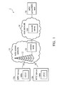
- FIG. 1 is a system diagram of an exemplary telecommunication system 1 supporting machine type communication.
- the telecommunication system 1 comprises MTC devices 10a and 10b, a radio access network 11, a core network 16, and an MTC server/MTC user 18.
- the MTC devices 10a and 10b are wirelessly coupled to the radio access network 11, and the core network 16, subsequently to the MTC server/MTC user 18 through wired, wireless, or combinational connection.
- the radio access network 11 comprises base station 12 and a control node 14 coupled thereto.
- the MTC devices 10a and 10b are in communication with the base station 12 through radio channels therebetween.
- the MTC devices 10a and 10b are user equipments configured for the MTC, and may be handhold mobile phones, laptop equipped with broadband network adaptors, or any other device capable of communicating.
- the base station 12 provides cell coverage area to serve telecommunication services to any mobile device therein. Although only one base station 12 is shown in the telecommunication system 1, it should be appreciated that more than one base station may be incorporated to provide the cell coverage area, and the base station 12 can serve more than one cell coverage area.
- the telecommunication service may include second, third, fourth generation telecommunication systems such as Global System for Mobile communications (GSM) system, Universal Mobile Telecommunications System (UMTS), and Long Term Evolution (LTE) system, etc.
- GSM Global System for Mobile communications
- UMTS Universal Mobile Telecommunications System
- LTE Long Term Evolution
- the control node 14 may be a base station controller (BSC) in the GSM system, or a radio network controller (RNC) in the UMTS radio access network (UTRAN).
- the control node 14 may be a base station controller (BSC) in the GSM system, or a radio network controller (RNC) in the UMTS radio access network (UTRAN).
- the control node 14 controls operations of the base station 12 and provides access to the core network 16.
- the core network 16 provides various services to mobile stations subscriber thereto through the access network.
- the core network 16 may be a public land mobile network (PLMN) that provides mobile communication services to the public.
- the core network 16 may comprise a network server 160 that serves to monitor and report MTC events in an MTC group of the MTC devices 10a and 10b.
- the network server 160 may be Serving GPRS Support Node / Mobility Management Entity (SGSN/MME), Gateway GPRS Support Node / Packet data network GateWay (GGSN/P-GW), PCRF, Home Location Register / Home Subscriber Server(HLR/HSS), or a combination thereof.
- SGSN/MME Serving GPRS Support Node / Mobility Management Entity
- GGSN/P-GW Gateway GPRS Support Node / Packet data network GateWay
- PCRF Home Location Register / Home Subscriber Server
- MTC devices Although only two MTC devices are shown in the FIG. 1 , it should be appreciated that more MTC devices may be incorporated in the MTC group.
- An MTC subscriber is the MTC server/MTC user 18 that subscribes to one or more MTC service from a network operator to monitor the MTC devices in the MTC groups.
- the MTC server/MTC user 18 configures the MTC event that it is interested in monitoring at the network server 160.
- the network provider such as a GSM operator provides the MTC service by monitoring the corresponding MTC event in the MTC group of the MTC devices, such that when the corresponding MTC event occurs at one MTC device in the MTC group, the network provider can detect the corresponding MTC event and report to the MTC server/MTC user 18.
- the MTC server and MTC user are bundled together in the FIG. 1 , those skilled in the art should appreciate that the MTC server and the MTC user may be implemented at different locations.
- the MTC server may be located at the core network 16.
- the MTC server has an interface accessible by the MTC user, performs service for the MTC user and communicates with the network server 160.
- the MTC monitoring MTC feature comprises one or more of the following MTC event type, but not limited thereto:
- FIG. 2 is a flowchart of an exemplary MTC event monitoring method 3 according to the invention, incorporating the network server 160 in FIG. 1 .
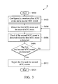
- Step S300 the network server 160 is initiated to monitor any configured MTC event at one or more MTC devices in an MTC group according to the MTC event monitoring method 3.
- the network operator / MTC server / MTC user 18 configures one or more MTC events to be monitored during initiation in Step S300, where the configured MTC event is of different MTC event type.
- a detection sensitivity (DS) threshold Th DS at the network server 160 is configured by the network operator, the MTC server, or the MTC user.
- the DS threshold Th DS may be associated with a time, a distance, a number of occurrences, or a probability. The higher the DS threshold Th DS is, the less sensitive it is for the network server 160 to detect an MTC event.
- the measure unit of the DS threshold TH DS may be fixed or configurable by the network operator or the MTC server/ MTC user 18.
- the MTC user 18 can configure the network server 160 to detect any behavior not aligned with an activated time controlled MTC feature and set up a first DS threshold TH DS to 4 time units representing the difference of time duration between the transmission duration and allocated grant transmission duration, wherein the time unit thereof is defined by the network operator.
- the network server 160 performs specific actions if the network server 160 detects the event with difference of time duration larger than or equal to 4 time units.
- the MTC features include time control, low mobility, small data transmission, etc, which are stored in the subscription of the MTC device in HSS/HLR.
- the configured DS threshold TH DS can be stored in a register or memory unit in the network server 160.
- the Network operator, the MTC server, or the MTC user can configure specific DS thresholds TH DS corresponding to MTC events to be detected.
- the DS thresholds TH DS for any MTC event may be the same for all MTC devices in any MTC group.
- Step S304 the network server 160 determines the MTC event in the MTC device and an associated DS parameter P DS .
- the associated DS parameter P DS has the same data type and measure unit as the DS threshold TH DS . Therefore the associated DS parameter P DS may also be associated with a time, a distance, a number of occurrences, or a probability.
- the network server 160 receives uplink transmission from the MTC device 10a outside of the grant time interval for 1 time unit, thus, the network server 160 determines the MTC event as the behavior is not aligned with the activated time control MTC feature. If this is the very first detected MTC event upon startup of the method 3, the associated DS parameter P DS is set as 1 time unit. Otherwise the P DS is incremented by 1 (P DS +1).
- the associated DS parameter P DS is reset to zero when no MTC event is identified in a time interval of one time unit.
- Step S306 the network server 160 compares the associated DS parameter P DS with the DS threshold TH DS to determine whether the associated DS parameter P DS equals to or exceeds the DS threshold Th DS . If so, the MTC event monitoring method 3 continues on step S308, and returns to step S304 if otherwise. If the associated DS parameter P DS is less than or equal to the DS threshold Th DS , the detected MTC event is not affirmative enough to be considered as a confirmed MTC event, thus the MTC event monitoring method 3 returns to steps S304 and continues monitoring the MTC event and the associated DS parameter P DS until the associated DS parameter P DS equals to or exceeds the DS threshold Th DS and the MTC event is confirmed.
- Step S308 the network server 160 reports the MTC event to the MTC server / MTC user 18.
- the network server 160 determines that the detected MTC event is a confirmed event and reports the MTC event to the MTC user through the MTC server.
- the MTC event report may comprise the MTC device, the detected MTC event thereof, and the associated DS parameter P DS .
- the MTC event report may further comprise a notification informing vandalism or theft of the MTC device.
- the network server 160 may reduce the transmission resource allocated to the MTC device according to the associated DS parameter P DS .
- the transmission resource may comprise the grant time interval, communication window, and bandwidth for data transmission, etc.
- the network server 160 may reduce the allocated transmission resource with increasing value of the associated DS parameter P DS .
- the network server 160 may also allocate no transmission resource to the MTC device when the associated DS parameter P DS equals to or exceeds the DS threshold Th DS .
- Step S310 the MTC event monitoring method 3 is complete and exited.
- the network server 160 may also perform one or more MTC event detection according to the MTC event monitoring method 3 concurrently or separately.
- the DS threshold TH DS is a time difference between the grant time interval and a transmission duration threshold
- the associated DS parameter P DS is a time difference between the grant time interval and detected transmission duration.
- the network operator / MTC server / MTC user 18 sets the DS threshold Th DS at the network server 160 (S302).
- the network server 160 determines that the DS parameter P DS is associated with the MTC event according to the detected transmission duration (S304), and compares the associated DS parameter P DS with the DS threshold TH DS (S306).
- the network server 160 reports the MTC event to the MTC server / MTC user 18 whenever detecting that the MTC event is not aligned with the time controlled MTC feature (S308).
- the DS threshold TH DS is 4, the network server 160 reports the MTC event to the MTC server / MTC user 18 when the time difference between the grant time interval and detected transmission duration is equal to or exceeded by 4 time units (S308).
- the DS threshold TH DS is a distance difference between the predetermined area (points of attachment) and an area threshold
- the associated DS parameter P DS is a distance difference between the predetermined area and a current location of the MTC device.
- the HLR/HSS holds information representing the predetermined area.
- the information may comprise allowed points of attachment of the MTC device.
- the allowed points of attachment and the current location may be indicated by tracking area indexes (TAI).
- TAI tracking area indexes
- the network operator / MTC server / MTC user 18 configures the network server 160 to monitor the current location (point of the attachment) for the MTC devices in the MTC group (S300).
- the network server 160 may be a SGSN/MME, a HLR/HSS, or both.
- the network operator / MTC server / MTC user 18 sets the DS threshold Th DS at the network server 160 (S302).
- the SGSN/MME 2 determines that the DS parameter P DS is associated with the MTC event according to the current location (S304), and compares the associated DS parameter P DS with the DS threshold TH DS (S306).
- the network server 160 reports the MTC event to the MTC server / MTC user 18 whenever detecting that the current location is equal to or exceeds the predetermined area (S308).
- the network server 160 reports the MTC event when the distance difference between the predetermined area and a current location of the MTC device equals to or exceeds 10 distance units (S308).
- the MTC device is allowed to attach to a neighboring SGSN/MME exceeding the predetermined points of attachment.
- the distance unit can be fixed or configurable by the network operator / MTC server / MTC user, and may be, for example, 10 meter.
- the DS threshold TH DS is a number of occurrences of an MTC event.
- the network operator / MTC server / MTC user 18 configures the network server 160 to monitor the event of loss of connectivity at the MTC device.
- the network operator / MTC server / MTC user 18 sets the DS threshold Th DS at the network server 160 (S302).
- the network server 160 determines the DS parameter P DS associated with the MTC event according to the number of times the connectivity is lost (S304), and compares the associated DS parameter P DS with the DS threshold Th DS (S306).
- the network server 160 reports the MTC event to the MTC server / MTC user 18 whenever detecting the loss of the connectivity to the MTC device (S308).
- the network server 160 reports the MTC event to the MTC server / MTC user 18 when the connectivity to the MTC is lost for 4 or more times (S308).
- the maximum number of occurrences of the DS threshold TH DS is fixed or configurable by the network operator or the MTC server/user.
- the DS threshold Th DS is time duration of an MTC event.
- the MTC server / MTC user 18 configures the network server 160 to monitor any loss of connectivity at the MTC device.
- the network operator / MTC server / MTC user 18 sets the DS threshold Th DS at the network server 160 (S302).
- the network server 160 determines the DS parameter P DS associated with the MTC event according to the time duration of the lost connectivity to the MTC device(S304), and compares the associated DS parameter P DS with the DS threshold TH DS (S306).
- the network server 160 reports the MTC event to the MTC server / MTC user 18 whenever detecting that the loss of the connectivity to the MTC device has occurred for longer than 1 time unit (S308).
- the network server 160 reports the MTC event when the connectivity to the MTC is lost for longer than 4 time units (S308).
- the time unit may be 10 minutes, and is fixed or configurable by the network operator or the MTC server/user.
- the MTC event monitoring method 3 employs the detection sensitivity threshold to reduce incorrect MTC event detection, and increase reliability of the MTC event determination.
- FIG. 3 is a flowchart of an exemplary MTC event monitoring method 4 according to the invention, incorporating the network server 160 in FIG. 1 .
- Step S400 the network server 160 is initiated to monitor two or more MTC events at one or more MTC devices according to the MTC event monitoring method 4.
- the network server 160 may be a SGSN/MME, a GGSN/P-GW, a PCRF, or HLR/HSS, or a combination thereof.
- the MTC event monitoring method 4 employs multiple MTC events to reduce incorrect MTC event detection and increase reliability of MTC event determination.
- the network server 160 are configured to monitor a first MTC event and a second MTC event sequentially or in parallel.
- the first and second MTC events are either of different event types occurred at the same MTC device, or of the same event type occurred at different MTC devices within a MTC group.
- Step S404 the network server 160 detects the first MTC event and the second MTC event configured in Step S402. If the first MTC event is detected, since any single MTC event may be detected due to a random accident or erroneous determination, the network server 160 withholds the MTC event report for the first MTC event and in Step S406, proceeds to check if the second MTC event is detected. Since the second MTC event may be correlated to the first one, when the first and second MTC events are both detected, the first MTC event is more probable to happen, than if just the first MTC event is detected. Thus, in Step 408, it is determined whether the first and second MTC events are both detected. If so, the MTC event monitoring method 4 continues on to Step S412, and if otherwise the method 4 returns to Step S404 to continuously detect the second MTC event.
- Step S412 the network server 160 reports the first and the second MTC events.
- the network server 160 determines that both MTC events are correct and reports both MTC events to the MTC server / MTC user 18.
- the network server 160 may reduce transmission resources allocated to the first or second MTC device when both the first and second MTC events are detected concurrently or consecutively.
- Step S414 the MTC event monitoring method 4 is complete and exited.
- the detection sensitivity threshold and parameter used in the MTC event monitoring method 3 can also be applied in the MTC event monitoring method 4, so as to increase the reliability and accuracy of the MTC event monitoring method 4.
- the detection sensitivity threshold and parameter e.g. the number of occurrence
- the detection sensitivity threshold and parameter can be introduced here to reduce incorrect MTC event detection and increase reliability of the MTC event monitoring method 4.
- the first and second MTC events are of different event types occurred at the same MTC device.
- the network operator/MTC server/MTC user 18 configures two or more MTC event types to be monitored during the initiation of the MTC event monitoring method 4. For instance, the network server 160 detects a loss of connectivity from an MTC device as the first MTC event (S404). The network sever 160 is then triggered to check if the second MTC event is detected on the same MTC device(S406).
- the type of the second MTC event is different from that of the first MTC event, and may be, for example, a change in the point of the attachment.
- the network server 160 determines whether the first and second MTC events have both occurred (S408). If so, the network server 160 reports both the first and second MTC events to the MTC server / MTC user 18 (S412), and the method 4 is exited (S414). If not, the network server 160 returns to Step 406 to continuously check if the second MTC event is detected. It should be noted that people skilled in the art can easily extend this embodiment to the case where more than two correlated MTC event types are monitored.
- the first and second MTC events are of the same event type occurred at different MTC devices within a MTC group.
- the network server 160 detects a loss of connectivity from a first MTC device as the first MTC event (S404). Subsequently, the network sever 160 checks if the second MTC event of a loss of connectivity is detected in a second MTC device (S406). The first and second MTC devices belong to the same MTC group. Next, the network server 160 determines whether the first and second MTC events have both occurred (S408). If so, the network server 160 reports both the first and second MTC events to the MTC server/MTC user 18 (S412), and the method 4 is exited (S414).
- Step 404 to Step 408 are repeated until the network server 160 guarantees that the evaluated false alarm probability is lower than the pre-configured false alarm probability, which is configured by the network operator / MTC server / MTC user.
- FIG. 4 is a flowchart of an exemplary MTC event reporting method 5 according to the invention, incorporating the network server 160 in FIG. 1 .
- Step S500 the network server 160 is initiated to report a configured MTC event to an MTC server / MTC user according to the MTC event monitoring method 5.
- the network server may be a SGSN/MME, a GGSN/P-GW, a PCRF, HLR/HSS server, or a combination thereof.
- the network operator / MTC server / MTC user 18 configures the MTC event to be monitored during the initiation in Step S500.
- the configured MTC event comprises one or more MTC event types.
- Step S502 the network server 160 determines that an MTC event has occurred at the MTC device. For example, the network server 160 determines the MTC device has loss connectivity thereof. The determined MTC event may be recorded at the memory module 24.
- Step S504 in response to the MTC event detection, the network server 160 reports the MTC event to the MTC server/MTC user 18.
- the network server 160 reports the MTC event.
- the network server 160 transmits a notification message comprising a cause value corresponding to a type of the MTC event.
- the cause value is hexadecimal
- the MTC event "change in the point of attachment" is indicated by H '2'
- the MTC event "loss of connectivity" is indicated by H '3'.
- the MTC server / MTC user 18 may confirm or resolve the MTC event accordingly. For example, the MTC user 18 may send an employee to check and correct the MTC event.
- Step S506 the network server 160 receives an MTC event response from the MTC server/ MTC user 18. After confirming or correcting the MTC event, the MTC server/ MTC user 18 sends the MTC event response informing that the reported MTC event has been confirmed, resolved, or cleared.
- Step S508 the network server 160 allocates a transmission resource to the MTC device according to the MTC event response.
- the MTC event response indicates that the MTC event has been resolved or cleared
- the network server 160 resets all MTC events.
- the network server 160 reduces the transmission resources allocated to the MTC device.
- the reduction in the transmission resources may be configured by the network operator / MTC server / MTC user 18 in a configured quantization level.
- the transmission resource comprises the grant time interval, transmission rate, or transmission bandwidth, etc.
- the network server 160 When the MTC event response indicates that the MTC event at the MTC device has been confirmed, the network server 160 reduces the grant time interval for the MTC device by a half thereof. When the MTC event response indicates that another MTC event at the MTC device has been confirmed, the network server 160 reduces the grant time interval for the MTC device by another half thereof.
- the HLR/HSS may comprise an MTC event response limit accessible by the network server 160. When the network server 160 receives a number of MTC event responses which are equal to or exceed the MTC event response limit, the MTC device will no longer receive any transmission resources from the network.
- Step S510 the MTC event reporting method 5 is complete and exited.
- the MTC event reporting method 5 utilizes the MTC event response from the MTC server / MTC user to confirm the MTC event, thus the network server 160 can take network action to the MTC device according to the MTC event response, resulting in decreased impact on the MTC network.
- the MTC event method 3, 4, and 5 can be utilized separately or conjointly by the network server 160, those who skilled in the art can adapt the methods described herein without deviation from to the principle of the invention to meet their own preference of MTC event methods.
- determining encompasses calculating, computing, processing, deriving, investigating, looking up (e.g., looking up in a table, a database or another data structure), ascertaining and the like. Also, “determining” may include resolving, detecting, selecting, choosing, establishing and the like.
- DSP digital signal processor
- ASIC application specific integrated circuit
- FPGA field programmable gate array signal
- a general purpose processor may be a microprocessor, but in the alternative, the processor may be any commercially available processor, controller, microcontroller or state machine.
Landscapes
- Engineering & Computer Science (AREA)
- Computer Networks & Wireless Communication (AREA)
- Signal Processing (AREA)
- Mobile Radio Communication Systems (AREA)
- Data Exchanges In Wide-Area Networks (AREA)
- Telephonic Communication Services (AREA)
Abstract
Description
- The present invention relates to machine type communication (MTC), and in particular relates to methods for monitoring and reporting an MTC event.
- Machine Type Communication (MTC) is the communication between devices without human interaction or intervention. The MTC may include establishing a connection between a network server and an MTC device identified in an MTC subscription. The MTC subscription is provided by the network operator to an MTC user. The network server communicates with the MTC device to detect an MTC event based on the MTC subscription, so that a network action can be performed to the MTC device upon the detection of the MTC event. However, incorrect MTC events may arise due to erroneous detection. Thus, methods for monitoring and reporting the MTC event are in need, to reduce incorrect MTC event detection and decrease impact on the MTC network and MTC device upon detecting that the MTC event.
- A detailed description is given in the following embodiments with reference to the accompanying drawings.
- An embodiment of an MTC event monitoring method in a network server is described, comprising
- a. configuring, by the network server, a detection sensitivity threshold,
- b. determining, by the network server, an MTC event at an MTC device and an associated detection sensitivity parameter, and
- c. reporting, by the network server, the MTC event to an MTC server only when the associated detection sensitivity parameter equals to or exceeds the detection sensitivity threshold.
- Another embodiment of an MTC event monitoring method in a network server is disclosed, comprising
- a. being configured to monitor a first MTC event and a second MTC event,
- b. detecting, by the network server, the first MTC event and the second MTC event,
- c. checking , by the network server, if the second MTC event is detected when the first MTC event is detected, and
- d. reporting, by the network server, at least one of the first and second MTC events only when the first and second MTC events are detected.
- Still another embodiment of an MTC event reporting method in a network server is revealed, comprising
- a. reporting, by the network server, the MTC event of an MTC device to an MTC server upon determination of the MTC event,
- b. receiving, by the network server, an MTC event response indicating that the MTC event has been resolved from the MTC server, and
- c. allocating, by the network server, a transmission resource to the MTC device according to the MTC event response.
- The present invention can be more fully understood by reading the subsequent detailed description and examples with references made to the accompanying drawings, wherein:
-
FIG. 1 is a system diagram of an exemplary telecommunication system 1 supporting machine type communication. -
FIG. 2 is a flowchart of an exemplary MTCevent monitoring method 3 according to the invention. -
FIG. 3 is a flowchart of an exemplary MTCevent monitoring method 4 according to the invention. -
FIG. 4 is a flowchart of an exemplary MTC event reporting method 5 according to the invention. - The following description is of the best-contemplated mode of carrying out the invention. This description is made for the purpose of illustrating the general principles of the invention and should not be taken in a limiting sense. The scope of the invention is best determined by reference to the appended claims. The 3GPP specifications are used to teach the spirit of the invention, and the invention is not limited thereto.
-
FIG. 1 is a system diagram of an exemplary telecommunication system 1 supporting machine type communication. The telecommunication system 1 comprisesMTC devices radio access network 11, acore network 16, and an MTC server/MTC user 18. TheMTC devices radio access network 11, and thecore network 16, subsequently to the MTC server/MTC user 18 through wired, wireless, or combinational connection. Theradio access network 11 comprisesbase station 12 and acontrol node 14 coupled thereto. TheMTC devices base station 12 through radio channels therebetween. TheMTC devices - The
base station 12 provides cell coverage area to serve telecommunication services to any mobile device therein. Although only onebase station 12 is shown in the telecommunication system 1, it should be appreciated that more than one base station may be incorporated to provide the cell coverage area, and thebase station 12 can serve more than one cell coverage area. The telecommunication service may include second, third, fourth generation telecommunication systems such as Global System for Mobile communications (GSM) system, Universal Mobile Telecommunications System (UMTS), and Long Term Evolution (LTE) system, etc. - The
control node 14 may be a base station controller (BSC) in the GSM system, or a radio network controller (RNC) in the UMTS radio access network (UTRAN). Thecontrol node 14 may be a base station controller (BSC) in the GSM system, or a radio network controller (RNC) in the UMTS radio access network (UTRAN). Thecontrol node 14 controls operations of thebase station 12 and provides access to thecore network 16. - The
core network 16 provides various services to mobile stations subscriber thereto through the access network. Thecore network 16 may be a public land mobile network (PLMN) that provides mobile communication services to the public. Thecore network 16 may comprise anetwork server 160 that serves to monitor and report MTC events in an MTC group of theMTC devices network server 160 may be Serving GPRS Support Node / Mobility Management Entity (SGSN/MME), Gateway GPRS Support Node / Packet data network GateWay (GGSN/P-GW), PCRF, Home Location Register / Home Subscriber Server(HLR/HSS), or a combination thereof. - Although only two MTC devices are shown in the
FIG. 1 , it should be appreciated that more MTC devices may be incorporated in the MTC group. - An MTC subscriber is the MTC server/
MTC user 18 that subscribes to one or more MTC service from a network operator to monitor the MTC devices in the MTC groups. The MTC server/MTC user 18 configures the MTC event that it is interested in monitoring at thenetwork server 160. The network provider such as a GSM operator provides the MTC service by monitoring the corresponding MTC event in the MTC group of the MTC devices, such that when the corresponding MTC event occurs at one MTC device in the MTC group, the network provider can detect the corresponding MTC event and report to the MTC server/MTC user 18. - Although the MTC server and MTC user are bundled together in the
FIG. 1 , those skilled in the art should appreciate that the MTC server and the MTC user may be implemented at different locations. For example, the MTC server may be located at thecore network 16. The MTC server has an interface accessible by the MTC user, performs service for the MTC user and communicates with thenetwork server 160. - The MTC monitoring MTC feature comprises one or more of the following MTC event type, but not limited thereto:
- 1. Behavior not aligned with activated MTC features. The MTC features comprise time control, low mobility, small data transmission, etc, which are stored in the subscription of the MTC device in HSS/HLR. One of the MTC features is time control, where the MTC devices are informed or randomly choose a grant time interval or a communication window, and the MTC devices are forbidden to access the
core network 16 outside of the grant time interval or the communication window. In one example, the MTC user/MTC server 18 activates the MTC feature of time control for the MTC group in thenetwork server 160 such as the HLR/HSS. When the MTC device in the MTC group accesses thecore network 16 outside of the grant time interval, the MTC event is triggered, and the HLR/HSS 160 reports the MTC event as the behavior is not aligned with the activated time control MTC feature. - 2. Change in the point of attachment. The MTC devices in each MTC group are defined by predetermined points of attachment. The predetermined point of attachment can be set up by the
MTC user 18 at thenetwork server 160 to define an area that theMTC device network server 160 can detect the change in the point of attachment and inform the MTC event to the MTC server/MTC user 18. - 3. Change of the association between the MTC device and a Universal Integrated Circuit Card (UICC). The UICC is a smart card inserted in
mobile stations MTC devices network server 160 may be the HLR/HSS that keeps a record of the IMSI and IMEI of the UICC in the MTC device, such that when theMTC device HSS 160 reports the MTC event to the MTC server/MTC user 18. - 4. Loss of connectivity. When it is no longer possible to establish signaling between the
MTC device network server 160, thenetwork server 16 determines a loss of connectivity to the MTC device thereof and reports the MTC event to the MTC server/MTC user 18. -
FIG. 2 is a flowchart of an exemplary MTCevent monitoring method 3 according to the invention, incorporating thenetwork server 160 inFIG. 1 . - In Step S300, the
network server 160 is initiated to monitor any configured MTC event at one or more MTC devices in an MTC group according to the MTCevent monitoring method 3. The network operator / MTC server /MTC user 18 configures one or more MTC events to be monitored during initiation in Step S300, where the configured MTC event is of different MTC event type. - In Step S302, a detection sensitivity (DS) threshold ThDS at the
network server 160 is configured by the network operator, the MTC server, or the MTC user. The DS threshold ThDS may be associated with a time, a distance, a number of occurrences, or a probability. The higher the DS threshold ThDS is, the less sensitive it is for thenetwork server 160 to detect an MTC event. The measure unit of the DS threshold THDS may be fixed or configurable by the network operator or the MTC server/MTC user 18.
For example, theMTC user 18 can configure thenetwork server 160 to detect any behavior not aligned with an activated time controlled MTC feature and set up a first DS threshold THDS to 4 time units representing the difference of time duration between the transmission duration and allocated grant transmission duration, wherein the time unit thereof is defined by the network operator. Thenetwork server 160 performs specific actions if thenetwork server 160 detects the event with difference of time duration larger than or equal to 4 time units. Examples of the MTC features include time control, low mobility, small data transmission, etc, which are stored in the subscription of the MTC device in HSS/HLR. - The configured DS threshold THDS can be stored in a register or memory unit in the
network server 160. The Network operator, the MTC server, or the MTC user can configure specific DS thresholds THDS corresponding to MTC events to be detected. The DS thresholds THDS for any MTC event may be the same for all MTC devices in any MTC group. - In Step S304, the
network server 160 determines the MTC event in the MTC device and an associated DS parameter PDS. The associated DS parameter PDS has the same data type and measure unit as the DS threshold THDS. Therefore the associated DS parameter PDS may also be associated with a time, a distance, a number of occurrences, or a probability. For example, thenetwork server 160 receives uplink transmission from theMTC device 10a outside of the grant time interval for 1 time unit, thus, thenetwork server 160 determines the MTC event as the behavior is not aligned with the activated time control MTC feature. If this is the very first detected MTC event upon startup of themethod 3, the associated DS parameter PDS is set as 1 time unit. Otherwise the PDS is incremented by 1 (PDS +1). The associated DS parameter PDS is reset to zero when no MTC event is identified in a time interval of one time unit. - In Step S306, the
network server 160 compares the associated DS parameter PDS with the DS threshold THDS to determine whether the associated DS parameter PDS equals to or exceeds the DS threshold ThDS. If so, the MTCevent monitoring method 3 continues on step S308, and returns to step S304 if otherwise. If the associated DS parameter PDS is less than or equal to the DS threshold ThDS, the detected MTC event is not affirmative enough to be considered as a confirmed MTC event, thus the MTCevent monitoring method 3 returns to steps S304 and continues monitoring the MTC event and the associated DS parameter PDS until the associated DS parameter PDS equals to or exceeds the DS threshold ThDS and the MTC event is confirmed. - In Step S308, the
network server 160 reports the MTC event to the MTC server /MTC user 18. When the associated DS parameter PDS equals to or exceeds the DS threshold ThDS, thenetwork server 160 determines that the detected MTC event is a confirmed event and reports the MTC event to the MTC user through the MTC server. The MTC event report may comprise the MTC device, the detected MTC event thereof, and the associated DS parameter PDS. The MTC event report may further comprise a notification informing vandalism or theft of the MTC device. - In response, the MTC user can take an action to remove or correct the MTC event in the MTC device. The
network server 160 may reduce the transmission resource allocated to the MTC device according to the associated DS parameter PDS. The transmission resource may comprise the grant time interval, communication window, and bandwidth for data transmission, etc. Thenetwork server 160 may reduce the allocated transmission resource with increasing value of the associated DS parameter PDS. Thenetwork server 160 may also allocate no transmission resource to the MTC device when the associated DS parameter PDS equals to or exceeds the DS threshold ThDS. - In Step S310, the MTC
event monitoring method 3 is complete and exited. Thenetwork server 160 may also perform one or more MTC event detection according to the MTCevent monitoring method 3 concurrently or separately. - In one example, the DS threshold THDS is a time difference between the grant time interval and a transmission duration threshold, and the associated DS parameter PDS is a time difference between the grant time interval and detected transmission duration. In Step S300, the MTC server /
MTC user 18 subscribes a MTC feature of time controlled, the network operator / MTC server /MTC user 18 configures thenetwork server 160 to monitor any behavior not aligned with the time controlled MTC feature at the MTC devices in the MTC group. Examples of the MTC features include time controlled, low mobility, small data transmission, etc, which are stored in the subscription of the MTC device in HSS/HLR. The network operator / MTC server /MTC user 18 sets the DS threshold ThDS at the network server 160 (S302). Upon detecting that the transmission duration for a data transmission of the MTC device equals to or exceeds the grant time interval, thenetwork server 160 determines that the DS parameter PDS is associated with the MTC event according to the detected transmission duration (S304), and compares the associated DS parameter PDS with the DS threshold THDS (S306). When the DS threshold ThDS is 0, thenetwork server 160 reports the MTC event to the MTC server /MTC user 18 whenever detecting that the MTC event is not aligned with the time controlled MTC feature (S308). When the DS threshold THDS is 4, thenetwork server 160 reports the MTC event to the MTC server /MTC user 18 when the time difference between the grant time interval and detected transmission duration is equal to or exceeded by 4 time units (S308). - In another example, the DS threshold THDS is a distance difference between the predetermined area (points of attachment) and an area threshold, and the associated DS parameter PDS is a distance difference between the predetermined area and a current location of the MTC device. The HLR/HSS holds information representing the predetermined area. The information may comprise allowed points of attachment of the MTC device. The allowed points of attachment and the current location may be indicated by tracking area indexes (TAI). The network operator / MTC server /
MTC user 18 configures thenetwork server 160 to monitor the current location (point of the attachment) for the MTC devices in the MTC group (S300). Thenetwork server 160 may be a SGSN/MME, a HLR/HSS, or both. The network operator / MTC server /MTC user 18 sets the DS threshold ThDS at the network server 160 (S302). Upon detecting that the MTC device at the current location equals to or exceeds the predetermined area, the SGSN/MME 2 determines that the DS parameter PDS is associated with the MTC event according to the current location (S304), and compares the associated DS parameter PDS with the DS threshold THDS (S306). When the DS threshold THDS is 0, thenetwork server 160 reports the MTC event to the MTC server /MTC user 18 whenever detecting that the current location is equal to or exceeds the predetermined area (S308). When the DS threshold THDS is 10, thenetwork server 160 reports the MTC event when the distance difference between the predetermined area and a current location of the MTC device equals to or exceeds 10 distance units (S308). As a consequence, the MTC device is allowed to attach to a neighboring SGSN/MME exceeding the predetermined points of attachment. The distance unit can be fixed or configurable by the network operator / MTC server / MTC user, and may be, for example, 10 meter. - In still another example, the DS threshold THDS is a number of occurrences of an MTC event. The network operator / MTC server /
MTC user 18 configures thenetwork server 160 to monitor the event of loss of connectivity at the MTC device. The network operator / MTC server /MTC user 18 sets the DS threshold ThDS at the network server 160 (S302). Upon detecting a loss of connectivity to the MTC device, thenetwork server 160 determines the DS parameter PDS associated with the MTC event according to the number of times the connectivity is lost (S304), and compares the associated DS parameter PDS with the DS threshold ThDS (S306). When the DS threshold ThDS is 1, thenetwork server 160 reports the MTC event to the MTC server /MTC user 18 whenever detecting the loss of the connectivity to the MTC device (S308). When the DS threshold THDS is 4, thenetwork server 160 reports the MTC event to the MTC server /MTC user 18 when the connectivity to the MTC is lost for 4 or more times (S308). The maximum number of occurrences of the DS threshold THDS is fixed or configurable by the network operator or the MTC server/user. - In yet another example, the DS threshold ThDS is time duration of an MTC event. The MTC server /
MTC user 18 configures thenetwork server 160 to monitor any loss of connectivity at the MTC device. The network operator / MTC server /MTC user 18 sets the DS threshold ThDS at the network server 160 (S302). Upon detecting a loss of connectivity to the MTC device, thenetwork server 160 determines the DS parameter PDS associated with the MTC event according to the time duration of the lost connectivity to the MTC device(S304), and compares the associated DS parameter PDS with the DS threshold THDS (S306). When the DS threshold ThDS is 1, thenetwork server 160 reports the MTC event to the MTC server /MTC user 18 whenever detecting that the loss of the connectivity to the MTC device has occurred for longer than 1 time unit (S308). When the DS threshold THDS is 4, thenetwork server 160 reports the MTC event when the connectivity to the MTC is lost for longer than 4 time units (S308). The time unit may be 10 minutes, and is fixed or configurable by the network operator or the MTC server/user. - The MTC
event monitoring method 3 employs the detection sensitivity threshold to reduce incorrect MTC event detection, and increase reliability of the MTC event determination. -
FIG. 3 is a flowchart of an exemplary MTCevent monitoring method 4 according to the invention, incorporating thenetwork server 160 inFIG. 1 . - In Step S400, the
network server 160 is initiated to monitor two or more MTC events at one or more MTC devices according to the MTCevent monitoring method 4. Thenetwork server 160 may be a SGSN/MME, a GGSN/P-GW, a PCRF, or HLR/HSS, or a combination thereof. The MTCevent monitoring method 4 employs multiple MTC events to reduce incorrect MTC event detection and increase reliability of MTC event determination. - In Step S402, the
network server 160 are configured to monitor a first MTC event and a second MTC event sequentially or in parallel. The first and second MTC events are either of different event types occurred at the same MTC device, or of the same event type occurred at different MTC devices within a MTC group. - In Step S404, the
network server 160 detects the first MTC event and the second MTC event configured in Step S402. If the first MTC event is detected, since any single MTC event may be detected due to a random accident or erroneous determination, thenetwork server 160 withholds the MTC event report for the first MTC event and in Step S406, proceeds to check if the second MTC event is detected. Since the second MTC event may be correlated to the first one, when the first and second MTC events are both detected, the first MTC event is more probable to happen, than if just the first MTC event is detected. Thus, inStep 408, it is determined whether the first and second MTC events are both detected. If so, the MTCevent monitoring method 4 continues on to Step S412, and if otherwise themethod 4 returns to Step S404 to continuously detect the second MTC event. - In Step S412, the
network server 160 reports the first and the second MTC events. When both the first and second MTC events are detected concurrently or consecutively, thenetwork server 160 determines that both MTC events are correct and reports both MTC events to the MTC server /MTC user 18. Thenetwork server 160 may reduce transmission resources allocated to the first or second MTC device when both the first and second MTC events are detected concurrently or consecutively. - In Step S414, the MTC
event monitoring method 4 is complete and exited. Please note that the detection sensitivity threshold and parameter used in the MTCevent monitoring method 3 can also be applied in the MTCevent monitoring method 4, so as to increase the reliability and accuracy of the MTCevent monitoring method 4. For example, when it is determined that the first and second MTC events are not both detected in Step S408, themethod 4 will return to Step S404. If another first MTC event is detected, then the detection sensitivity threshold and parameter (e.g. the number of occurrence) can be introduced here to reduce incorrect MTC event detection and increase reliability of the MTCevent monitoring method 4. - In one embodiment of the MTC
event monitoring method 4, the first and second MTC events are of different event types occurred at the same MTC device. Based on the subscribed MTC monitoring feature, the network operator/MTC server/MTC user 18 configures two or more MTC event types to be monitored during the initiation of the MTCevent monitoring method 4. For instance, thenetwork server 160 detects a loss of connectivity from an MTC device as the first MTC event (S404). The network sever 160 is then triggered to check if the second MTC event is detected on the same MTC device(S406). The type of the second MTC event is different from that of the first MTC event, and may be, for example, a change in the point of the attachment. Next, thenetwork server 160 determines whether the first and second MTC events have both occurred (S408). If so, thenetwork server 160 reports both the first and second MTC events to the MTC server / MTC user 18 (S412), and themethod 4 is exited (S414). If not, thenetwork server 160 returns to Step 406 to continuously check if the second MTC event is detected. It should be noted that people skilled in the art can easily extend this embodiment to the case where more than two correlated MTC event types are monitored. - In another embodiment of the MTC
event monitoring method 4, the first and second MTC events are of the same event type occurred at different MTC devices within a MTC group. For instance, thenetwork server 160 detects a loss of connectivity from a first MTC device as the first MTC event (S404). Subsequently, the network sever 160 checks if the second MTC event of a loss of connectivity is detected in a second MTC device (S406). The first and second MTC devices belong to the same MTC group. Next, thenetwork server 160 determines whether the first and second MTC events have both occurred (S408). If so, thenetwork server 160 reports both the first and second MTC events to the MTC server/MTC user 18 (S412), and themethod 4 is exited (S414). If not, thenetwork server 160 returns to Step 406 to continuously check if the second MTC event is detected. It should be noted that people skilled in the art can easily extend this another embodiment to the case where a MTC group including more than two MTC devices are monitored if a certain type of MTC event occurs. Alternatively, if this another embodiment is applied to a MTC group including more than two MTC devices, the number of occurrence of the detected MTC events can be introduced to Step S408 to help evaluate the false alarm probability. That is, the higher the number of occurrence is, the lower the false alarm probability becomes. Before reporting at Step 412, the Step 404 to Step 408 are repeated until thenetwork server 160 guarantees that the evaluated false alarm probability is lower than the pre-configured false alarm probability, which is configured by the network operator / MTC server / MTC user. -
FIG. 4 is a flowchart of an exemplary MTC event reporting method 5 according to the invention, incorporating thenetwork server 160 inFIG. 1 . - In Step S500, the
network server 160 is initiated to report a configured MTC event to an MTC server / MTC user according to the MTC event monitoring method 5. The network server may be a SGSN/MME, a GGSN/P-GW, a PCRF, HLR/HSS server, or a combination thereof. The network operator / MTC server /MTC user 18 configures the MTC event to be monitored during the initiation in Step S500. The configured MTC event comprises one or more MTC event types. - In Step S502, the
network server 160 determines that an MTC event has occurred at the MTC device. For example, thenetwork server 160 determines the MTC device has loss connectivity thereof. The determined MTC event may be recorded at the memory module 24. - Next In Step S504, in response to the MTC event detection, the
network server 160 reports the MTC event to the MTC server/MTC user 18. Thenetwork server 160 reports the MTC event. Thenetwork server 160 transmits a notification message comprising a cause value corresponding to a type of the MTC event. In one embodiment, the cause value is hexadecimal, the MTC event "change in the point of attachment" is indicated by H '2', and the MTC event "loss of connectivity" is indicated by H '3'. Upon receipt of the notification message, the MTC server /MTC user 18 may confirm or resolve the MTC event accordingly. For example, theMTC user 18 may send an employee to check and correct the MTC event. - In Step S506, the
network server 160 receives an MTC event response from the MTC server/MTC user 18. After confirming or correcting the MTC event, the MTC server/MTC user 18 sends the MTC event response informing that the reported MTC event has been confirmed, resolved, or cleared. - In Step S508, the
network server 160 allocates a transmission resource to the MTC device according to the MTC event response. When the MTC event response indicates that the MTC event has been resolved or cleared, thenetwork server 160 resets all MTC events. When the MTC event response indicates that the MTC event has been confirmed, thenetwork server 160 reduces the transmission resources allocated to the MTC device. The reduction in the transmission resources may be configured by the network operator / MTC server /MTC user 18 in a configured quantization level.
In one example, if time controlled MTC feature is activated, the transmission resource comprises the grant time interval, transmission rate, or transmission bandwidth, etc. When the MTC event response indicates that the MTC event at the MTC device has been confirmed, thenetwork server 160 reduces the grant time interval for the MTC device by a half thereof. When the MTC event response indicates that another MTC event at the MTC device has been confirmed, thenetwork server 160 reduces the grant time interval for the MTC device by another half thereof. The HLR/HSS may comprise an MTC event response limit accessible by thenetwork server 160. When thenetwork server 160 receives a number of MTC event responses which are equal to or exceed the MTC event response limit, the MTC device will no longer receive any transmission resources from the network. - In Step S510, the MTC event reporting method 5 is complete and exited.
- The MTC event reporting method 5 utilizes the MTC event response from the MTC server / MTC user to confirm the MTC event, thus the
network server 160 can take network action to the MTC device according to the MTC event response, resulting in decreased impact on the MTC network. - The
MTC event method network server 160, those who skilled in the art can adapt the methods described herein without deviation from to the principle of the invention to meet their own preference of MTC event methods. - As used herein, the term "determining" encompasses calculating, computing, processing, deriving, investigating, looking up (e.g., looking up in a table, a database or another data structure), ascertaining and the like. Also, "determining" may include resolving, detecting, selecting, choosing, establishing and the like.
- The various illustrative logical blocks, modules and circuits described in connection with the present disclosure may be implemented or performed with a general purpose processor, a digital signal processor (DSP), an application specific integrated circuit (ASIC), a field programmable gate array signal (FPGA) or other programmable logic device, discrete gate or transistor logic, discrete hardware components or any combination thereof designed to perform the functions described herein. A general purpose processor may be a microprocessor, but in the alternative, the processor may be any commercially available processor, controller, microcontroller or state machine.
- The operations and functions of the various logical blocks, modules, and circuits described herein may be implemented in circuit hardware or embedded software codes that can be accessed and executed by a processor.
- While the invention has been described by way of example and in terms of the preferred embodiments, it is to be understood that the invention is not limited to the disclosed embodiments. To the contrary, it is intended to cover various modifications and similar arrangements (as would be apparent to those skilled in the art). Therefore, the scope of the appended claims should be accorded the broadest interpretation so as to encompass all such modifications and similar arrangements.
Claims (15)
- A Machine Type Communication (MTC) event monitoring method in a network server, comprising: configuring, by the network server, a detection sensitivity threshold;
determining, by the network server, an MTC event at an MTC device and an associated detection sensitivity parameter; and
reporting, by the network server, the MTC event to an MTC server only when the associated detection sensitivity parameter equals to or exceeds the detection sensitivity threshold. - The MTC event monitoring method as claimed in claim 1, wherein:the detection sensitivity threshold and the associated detection sensitivity parameter are associated with time.
- The MTC event monitoring method as claimed in claim 1, wherein:the detection sensitivity threshold and the associated detection sensitivity parameter are associated with distance.
- The MTC event monitoring method as claimed in claim 1, wherein:the detection sensitivity threshold and the associated detection sensitivity parameter are associated with a number of occurrence.
- The MTC event monitoring method as claimed in claim 1, wherein:the detection sensitivity threshold and the associated detection sensitivity parameter are associated with a probability.
- The MTC event monitoring method as claimed in claim 1, wherein the network server is a SGSN/MME, a GGSN/P-GW, a PCRF, HLR/HSS, an MTC client, or an MTC server.
- The MTC event monitoring method as claimed in claim 1, further comprising:reducing a transmission resource allocated to the MTC device with an increasing associated detection sensitivity parameter upon determining the MTC event.
- An MTC event monitoring method in a network server, comprising: being configured to monitor a first MTC event and a second MTC event;
detecting, by the network server, the first MTC event and the second MTC event; checking , by the network server, if the second MTC event is detected when the first MTC event is detected; and
reporting, by the network server, at least one of the first and second MTC events only when the first and second MTC events are detected. - The MTC event monitoring method of Claim 8, wherein: the detecting step comprises detecting both the first MTC event and the second MTC event at a same MTC device;
wherein the first MTC event and the second MTC event are of different MTC event types. - The MTC event monitoring method of Claim 8, wherein: the detecting step comprises detecting the first MTC event at a first MTC device and detecting the second MTC event at a second MTC device;
wherein the first MTC event and the second MTC event are of a same MTC event type. - The MTC event monitoring method as claimed in claim 8, wherein the network server is a SGSN/MME, a GGSN/P-GW, a PCRF, an HLR/HSS, or a combination thereof.
- An MTC event reporting method in a network server, comprising: reporting, by the network server, the MTC event of an MTC device to an MTC server upon determination of the MTC event;
receiving, by the network server, an MTC event response indicating that the MTC event has been resolved from the MTC server; and
allocating, by the network server, a transmission resource to the MTC device according to the MTC event response. - The MTC event reporting method as claimed in claim 12, wherein the reporting step comprises:transmitting a notification message comprising a cause value corresponding to a type of the MTC event.
- The MTC event reporting method as claimed in claim 12, wherein the allocating step comprises:reducing, by the network server, a transmission resource allocated to the MTC device when the MTC event response confirms the MTC event.
- The MTC event reporting method as claimed in claim 12, further comprising:resetting, by the network server, the MTC event when the MTC event response indicates that the MTC event has been resolved.
Applications Claiming Priority (2)
| Application Number | Priority Date | Filing Date | Title |
|---|---|---|---|
| US33056610P | 2010-05-03 | 2010-05-03 | |
| US13/097,442 US8438278B2 (en) | 2010-05-03 | 2011-04-29 | Methods for monitoring and reporting MTC events |
Publications (2)
| Publication Number | Publication Date |
|---|---|
| EP2385657A2 true EP2385657A2 (en) | 2011-11-09 |
| EP2385657A3 EP2385657A3 (en) | 2011-12-07 |
Family
ID=44344030
Family Applications (1)
| Application Number | Title | Priority Date | Filing Date |
|---|---|---|---|
| EP11003609A Withdrawn EP2385657A3 (en) | 2010-05-03 | 2011-05-03 | Methods for monitoring and reporting MTC events |
Country Status (4)
| Country | Link |
|---|---|
| US (1) | US8438278B2 (en) |
| EP (1) | EP2385657A3 (en) |
| CN (1) | CN102238601B (en) |
| TW (1) | TWI428860B (en) |
Cited By (4)
| Publication number | Priority date | Publication date | Assignee | Title |
|---|---|---|---|---|
| WO2012131153A1 (en) * | 2011-03-30 | 2012-10-04 | Nokia Corporation | Random access data channel for machine type communications |
| EP3051710A1 (en) * | 2012-09-28 | 2016-08-03 | Intel Corporation | Machine type communication monitoring framework for 3gpp systems |
| WO2017152949A1 (en) * | 2016-03-08 | 2017-09-14 | Telefonaktiebolaget Lm Ericsson (Publ) | Core network signaling control |
| EP3248344A4 (en) * | 2015-01-12 | 2018-02-21 | Telefonaktiebolaget LM Ericsson (publ) | Methods and apparatus for monitoring and managing resource usage in a communication network |
Families Citing this family (26)
| Publication number | Priority date | Publication date | Assignee | Title |
|---|---|---|---|---|
| KR20110137652A (en) * | 2010-06-17 | 2011-12-23 | 삼성전자주식회사 | Wireless communication system and connection method between user terminal and mobility management entity |
| US20110310731A1 (en) * | 2010-06-18 | 2011-12-22 | Sharp Laboratories Of America, Inc. | Controlling network resource usage of machine type communication (mtc) devices |
| US9113322B2 (en) * | 2010-07-27 | 2015-08-18 | Telefonaktiebolaget L M Ericsson (Publ) | Machine-type communication subscription control |
| US8924537B2 (en) * | 2010-09-09 | 2014-12-30 | Hewlett-Packard Development Company, L.P. | Business processes tracking |
| AU2011314523B2 (en) * | 2010-10-12 | 2015-07-09 | Samsung Electronics Co., Ltd. | Method and apparatus of communicating machine type communication data over an Iu interface in a universal mobile telecommunications system |
| EP2628280B1 (en) * | 2010-10-13 | 2018-05-16 | Samsung Electronics Co., Ltd | Method and apparatus for multiplexing machine type communication data of multiple mtc devices in a wireless network environment |
| CN102548019B (en) * | 2010-12-15 | 2016-07-27 | 华为技术有限公司 | The foundation of common path and using method, the communication means of M2M and system |
| US9215645B2 (en) * | 2011-05-02 | 2015-12-15 | Telefonaktiebolaget L M Ericsson (Publ) | Controlling network accesses by radio terminals associated with access classes |
| US8655312B2 (en) * | 2011-08-12 | 2014-02-18 | F-Secure Corporation | Wireless access point detection |
| CN103096291B (en) * | 2011-11-04 | 2016-12-07 | 华为技术有限公司 | A data transmission method, mobility management entity and mobile terminal |
| EP2830338A4 (en) * | 2012-03-23 | 2015-12-30 | Nec Corp | SUBSCRIBER SERVER, MONITORING SERVER, MOBILE TERMINAL, CORRESPONDING METHOD, AND COMPUTER-READABLE MEDIUM |
| WO2013154576A1 (en) * | 2012-04-13 | 2013-10-17 | Nokia Siemens Networks Oy | Monitoring suspicious events in a cellular network |
| CN103384380B (en) * | 2012-05-02 | 2018-12-21 | 中兴通讯股份有限公司 | A kind of report method and related device of machine-type communication event |
| CN103684824B (en) * | 2012-09-13 | 2017-09-12 | 华为终端有限公司 | A kind of method and system of reporting events |
| US9973315B2 (en) | 2012-09-28 | 2018-05-15 | Intel Corporation | Systems and methods for semi-persistent scheduling of wireless communications |
| CN103716822A (en) * | 2012-10-09 | 2014-04-09 | 中兴通讯股份有限公司 | Monitoring method and apparatus |
| CN103781015A (en) * | 2012-10-17 | 2014-05-07 | 中兴通讯股份有限公司 | Method and system for monitoring machine type communication device events, and network side |
| WO2014071171A2 (en) * | 2012-11-02 | 2014-05-08 | Interdigital Patent Holdings, Inc. | Method and apparatus for machine-type communication device monitoring |
| US11463211B2 (en) * | 2012-12-21 | 2022-10-04 | Nec Corporation | MTC-IWF entity, SCS entity, signaling method, and computer readable medium |
| US10334416B2 (en) * | 2013-03-15 | 2019-06-25 | Alcatel Lucent | Control of group triggers for MTC services |
| US9173120B2 (en) * | 2013-03-28 | 2015-10-27 | Telefonaktiebolaget Lm Ericsson (Publ) | System and method for processing received data in a wireless network |
| US9210687B1 (en) * | 2013-09-25 | 2015-12-08 | Sprint Spectrum L.P. | Management of wireless service in a dual RAN arrangement |
| US10028075B2 (en) | 2013-10-03 | 2018-07-17 | At&T Intellectual Property I, L.P. | Intelligent machine-to-machine (IM2M) devices |
| CN106462536B (en) * | 2014-05-23 | 2019-11-08 | 富士通互联科技有限公司 | Machine type communication event detection method, system and non-transitory computer readable medium |
| US9930516B2 (en) | 2015-05-15 | 2018-03-27 | Samsung Electronics Co., Ltd. | UE monitoring configuration method and apparatus |
| CN107888439A (en) * | 2016-09-30 | 2018-04-06 | 中兴通讯股份有限公司 | A kind of Internet of Things monitor method, apparatus and system |
Family Cites Families (6)
| Publication number | Priority date | Publication date | Assignee | Title |
|---|---|---|---|---|
| FI108269B (en) | 1999-02-26 | 2001-12-14 | Nokia Corp | A method for determining a confidence limit in a telecommunications system |
| FR2881009B1 (en) | 2005-01-17 | 2007-04-20 | Bouygues Telecom Sa | METHOD FOR DETECTING EVENTS IN A TELECOMMUNICATIONS NETWORK |
| US20060274703A1 (en) * | 2005-06-07 | 2006-12-07 | Connelly Stephen P | Method and apparatus of filtering and viewing real-time detail records based upon user specific criteria |
| AU2011215752A1 (en) * | 2010-02-12 | 2012-09-06 | Interdigital Patent Holdings, Inc | Access control and congestion control in machine-to-machine communication |
| KR101857404B1 (en) * | 2010-02-12 | 2018-06-20 | 인터디지탈 패튼 홀딩스, 인크 | Method and apparatus for supporting machine-type communications |
| EP2567555A1 (en) * | 2010-05-03 | 2013-03-13 | Interdigital Patent Holdings, Inc. | Allocation of internet (ip) addresses and usage during short message service (sms) transmission |
-
2011
- 2011-04-29 US US13/097,442 patent/US8438278B2/en not_active Expired - Fee Related
- 2011-05-03 EP EP11003609A patent/EP2385657A3/en not_active Withdrawn
- 2011-05-03 TW TW100115431A patent/TWI428860B/en not_active IP Right Cessation
- 2011-05-03 CN CN201110113217.XA patent/CN102238601B/en not_active Expired - Fee Related
Non-Patent Citations (1)
| Title |
|---|
| None |
Cited By (10)
| Publication number | Priority date | Publication date | Assignee | Title |
|---|---|---|---|---|
| WO2012131153A1 (en) * | 2011-03-30 | 2012-10-04 | Nokia Corporation | Random access data channel for machine type communications |
| EP3051710A1 (en) * | 2012-09-28 | 2016-08-03 | Intel Corporation | Machine type communication monitoring framework for 3gpp systems |
| US9942791B2 (en) | 2012-09-28 | 2018-04-10 | Intel Corporation | Machine type communication monitoring framework for 3GPP systems |
| EP3370344A1 (en) * | 2012-09-28 | 2018-09-05 | Intel Corporation | Machine type communication monitoring framework for 3 gpp systems |
| US10524156B2 (en) | 2012-09-28 | 2019-12-31 | Intel Corporation | Machine type communication monitoring framework for 3GPP systems |
| US11089500B2 (en) | 2012-09-28 | 2021-08-10 | Apple Inc. | Machine type communication monitoring framework for 3GPP systems |
| EP3248344A4 (en) * | 2015-01-12 | 2018-02-21 | Telefonaktiebolaget LM Ericsson (publ) | Methods and apparatus for monitoring and managing resource usage in a communication network |
| US10405159B2 (en) | 2015-01-12 | 2019-09-03 | Telefonaktiebolaget Lm Ericsson (Publ) | Methods and apparatus for monitoring and managing resource usage in a communication network |
| WO2017152949A1 (en) * | 2016-03-08 | 2017-09-14 | Telefonaktiebolaget Lm Ericsson (Publ) | Core network signaling control |
| US11006361B2 (en) | 2016-03-08 | 2021-05-11 | Telefonaktiebolaget Lm Ericsson (Publ) | Core network signaling control |
Also Published As
| Publication number | Publication date |
|---|---|
| CN102238601A (en) | 2011-11-09 |
| US20110270973A1 (en) | 2011-11-03 |
| US8438278B2 (en) | 2013-05-07 |
| TW201203179A (en) | 2012-01-16 |
| TWI428860B (en) | 2014-03-01 |
| CN102238601B (en) | 2014-09-10 |
| EP2385657A3 (en) | 2011-12-07 |
Similar Documents
| Publication | Publication Date | Title |
|---|---|---|
| US8438278B2 (en) | Methods for monitoring and reporting MTC events | |
| CN101208977B (en) | Evaluation of random access lead code | |
| US8681622B2 (en) | Policy and charging rules function (PCRF) and performance intelligence center (PIC) based congestion control | |
| US10694448B2 (en) | Method and apparatus for implementing access control | |
| US8953538B2 (en) | Network access method and system for machine type communications | |
| US20130332627A1 (en) | Enabling ip-communication with a machine to machine unit | |
| EP2624656A1 (en) | Method and system for radio resource control | |
| EP2416604A1 (en) | Handling signaling congestion and related communication device | |
| EP2515583A1 (en) | Method and system for controlling machine type communication equipment to access network | |
| US11936541B2 (en) | Method and apparatus for prediction of device failure | |
| KR102058876B1 (en) | Method and apparatus for solving congestion situation in device to device communication | |
| KR101723930B1 (en) | Wireless local area network (wlan) traffic load measurement provisioning to wireless cellular networks | |
| CN105516986A (en) | Method for detecting pseudo base station, terminal, data processor and system | |
| EP3119130B1 (en) | Restriction control device and restriction control method | |
| EP1379097A1 (en) | Method of furnishing illegal mobile equipment user information | |
| EP3158806B1 (en) | Method and arrangement for triggering paging profiling | |
| EP3113558B1 (en) | Method and user equipment for generating monitoring report | |
| US20110151862A1 (en) | Performance management for a telecommunication network | |
| KR102333866B1 (en) | Method and Apparatus for Checking Problem in Mobile Communication Network | |
| JP2013519263A (en) | Method and apparatus for MTC user equipment to detect and report a predetermined event to an MTC server | |
| EP2915344B1 (en) | Method, location determiner, computer program and computer program product for determining a location of a mobile communication terminal | |
| CN113811022B (en) | Abnormal terminal rejection method, system, device and storage medium | |
| US20130051336A1 (en) | Access method and system for machine-type communication terminal and machine-type communication terminal | |
| CN102833733B (en) | A kind of method and system for monitoring the movement of Hypomobility terminal location | |
| CN102724649A (en) | Method for monitoring position change of low mobility terminal and system thereof |
Legal Events
| Date | Code | Title | Description |
|---|---|---|---|
| PUAL | Search report despatched |
Free format text: ORIGINAL CODE: 0009013 |
|
| 17P | Request for examination filed |
Effective date: 20110503 |
|
| AK | Designated contracting states |
Kind code of ref document: A2 Designated state(s): AL AT BE BG CH CY CZ DE DK EE ES FI FR GB GR HR HU IE IS IT LI LT LU LV MC MK MT NL NO PL PT RO RS SE SI SK SM TR |
|
| AX | Request for extension of the european patent |
Extension state: BA ME |
|
| PUAI | Public reference made under article 153(3) epc to a published international application that has entered the european phase |
Free format text: ORIGINAL CODE: 0009012 |
|
| AK | Designated contracting states |
Kind code of ref document: A3 Designated state(s): AL AT BE BG CH CY CZ DE DK EE ES FI FR GB GR HR HU IE IS IT LI LT LU LV MC MK MT NL NO PL PT RO RS SE SI SK SM TR |
|
| AX | Request for extension of the european patent |
Extension state: BA ME |
|
| RIC1 | Information provided on ipc code assigned before grant |
Ipc: H04L 12/24 20060101ALI20111028BHEP Ipc: H04W 72/04 20090101ALI20111028BHEP Ipc: H04L 12/26 20060101AFI20111028BHEP |
|
| 17Q | First examination report despatched |
Effective date: 20111214 |
|
| STAA | Information on the status of an ep patent application or granted ep patent |
Free format text: STATUS: THE APPLICATION IS DEEMED TO BE WITHDRAWN |
|
| 18D | Application deemed to be withdrawn |
Effective date: 20130205 |