EP2386040B1 - Kappe und entenschnabelventil für einen weichen behälter - Google Patents
Kappe und entenschnabelventil für einen weichen behälter Download PDFInfo
- Publication number
- EP2386040B1 EP2386040B1 EP20100700088 EP10700088A EP2386040B1 EP 2386040 B1 EP2386040 B1 EP 2386040B1 EP 20100700088 EP20100700088 EP 20100700088 EP 10700088 A EP10700088 A EP 10700088A EP 2386040 B1 EP2386040 B1 EP 2386040B1
- Authority
- EP
- European Patent Office
- Prior art keywords
- cap
- fitment
- probe
- duckbill
- seal
- Prior art date
- Legal status (The legal status is an assumption and is not a legal conclusion. Google has not performed a legal analysis and makes no representation as to the accuracy of the status listed.)
- Active
Links
Images



Classifications
-
- B—PERFORMING OPERATIONS; TRANSPORTING
- B65—CONVEYING; PACKING; STORING; HANDLING THIN OR FILAMENTARY MATERIAL
- B65D—CONTAINERS FOR STORAGE OR TRANSPORT OF ARTICLES OR MATERIALS, e.g. BAGS, BARRELS, BOTTLES, BOXES, CANS, CARTONS, CRATES, DRUMS, JARS, TANKS, HOPPERS, FORWARDING CONTAINERS; ACCESSORIES, CLOSURES, OR FITTINGS THEREFOR; PACKAGING ELEMENTS; PACKAGES
- B65D75/00—Packages comprising articles or materials partially or wholly enclosed in strips, sheets, blanks, tubes or webs of flexible sheet material, e.g. in folded wrappers
- B65D75/52—Details
- B65D75/58—Opening or contents-removing devices added or incorporated during package manufacture
- B65D75/5861—Spouts
- B65D75/5872—Non-integral spouts
- B65D75/5877—Non-integral spouts connected to a planar surface of the package wall
-
- Y—GENERAL TAGGING OF NEW TECHNOLOGICAL DEVELOPMENTS; GENERAL TAGGING OF CROSS-SECTIONAL TECHNOLOGIES SPANNING OVER SEVERAL SECTIONS OF THE IPC; TECHNICAL SUBJECTS COVERED BY FORMER USPC CROSS-REFERENCE ART COLLECTIONS [XRACs] AND DIGESTS
- Y10—TECHNICAL SUBJECTS COVERED BY FORMER USPC
- Y10T—TECHNICAL SUBJECTS COVERED BY FORMER US CLASSIFICATION
- Y10T137/00—Fluid handling
- Y10T137/7722—Line condition change responsive valves
- Y10T137/7837—Direct response valves [i.e., check valve type]
- Y10T137/7879—Resilient material valve
- Y10T137/788—Having expansible port
- Y10T137/7882—Having exit lip
Definitions
- the present disclosure relates to a fitment for use with a collapsible container for dispensing liquids or semi-solids from the collapsible container. More particularly, the present disclosure relates to a fitment comprising a duckbill flip cap for use on a collapsible container for dispensing liquids and semi-solids from the container.
- Many systems are used for dispensing liquids or semi-solids from a disposable package consisting of a flexible collapsible bag in a corrugated box. Such a package is commonly referred to as a bag-in-box dispensing package.
- these systems include a bag that is provided with a fitment in the form of a spout through which filling and dispensing occur. It is generally desirable to provide a quick-disconnect coupling between the spout and the service line of the pump or other type of beverage mixing and dispensing system.
- closures often employ complicated sealing structures to provide an adequate seal that prevents a product spill.
- elastomeric check-valves and O-ring seals have been employed.
- these closure valves are not cost effective, as multiple parts are required for assembly.
- connection types that include an insert and/or cap connected with a fluid source, such as, a bag or bag-in-box.
- the insert is coupled with a connector or coupler body that can access a fluid dispensing system, such as, a fluid line.
- a fluid dispensing system such as, a fluid line.
- connectors employ a piercing member at one end so as to puncture a membrane seal disposed on the insert when the connector is mated with the insert for fluid dispensing.
- connectors used to mate with the insert on the fluid source are produced so as to be reusable.
- the present invention provides a non-disposable coupling valve assembly that can be utilized with a variety of fluid conduit adaptors.
- Disposable containers are routinely used in commercial and industrial applications to transport and dispense a variety of liquids or fluids, such as, food products, cleaning solutions, detergents, and other products.
- Some containers are constructed of semi-rigid plastic while others are constructed of flexible plastic and are often supported within a protective box.
- valve structures that facilitate dispensing fluids to or from the containers.
- the valve structures are preferably designed to quickly couple with exterior coupling members.
- the female coupling includes a releasable locking or quick-connecting/disconnecting mechanism for locking the male and female couplings together in a coupled state.
- U.S. Pat. No. 4,436,125 discloses a quick-connect/disconnect coupling assembly.
- a female coupling member includes a poppet valve assembly that functions as an automatic shut-off of the fluid passageway in the female coupling member when the female coupling member is not interconnected to the male coupling member.
- the present invention is a fitment for use on a collapsible bag for dispensing of liquids and semi-solids from the bag, the fitment comprising:
- the term “about” or “approximately” means within 20%, preferably within 10%, and more preferably within 5% of a given value or range.
- the fitment of the present invention is attached to a liquid container, which usually is a flexible bag of a plastic material or a semi-rigid container, also of a plastic material, that holds liquids or semi-solids that are to be dispensed.
- a liquid container which usually is a flexible bag of a plastic material or a semi-rigid container, also of a plastic material, that holds liquids or semi-solids that are to be dispensed.
- the fitment can be tailored to the size of the bag or container so that a desired level of flow can be achieved.
- a wide variety of liquids or semi-solids can be dispensed using the fitment, such as liquid foods, for example, coffee, soda, milk, cooking oil, or liquid chemicals of various types, such as, detergents, cleaning liquids, hand soap, pastes, glue.
- FIG. 1 shows an exploded bottom view of the filment assembly of this invention.
- a probe 10 is fitted into flip cap 30 having a flip lid 31 with a pull tab 34.
- Cap duckbill 20 is positioned in the bottom of the flip cap 30.
- a duckbill lock ring 23 is positioned between the cap duckbill 20 and the spout 50.
- the duckbill lock ring 23 Upon engagement of the cap duckbill 20 with the duckbill lock ring 23 and the spout 50, the duckbill lock ring 23 locks into cap 30 and holds the duckbill product flow opening 21 in the cap duckbill 20, closed, and prevents seepage or leakage of liquid that is to be dispensed from the bag or container (not shown) to which spout 50 is attached. Extended periods of holding the liquid container at cold temperatures can cause distortion of the cap duckbill 20 thereby allowing liquid to seep through the flow opening 21. The use of the duckbill locking ring 23 prevents such seepage.
- Probe 10 through which material from the bag or container is dispensed typically is a molded thermoplastic material usually a polyolefin, such as, polyethylene, copolymers and terpolymers of polyethylene, polypropylene, copolymers and terpolymers of polypropylene, polybutylene and copolymers and terpolymers thereof, fluorocarbon polymers and copolymers thereof, polyvinyl chloride and copolymers thereof, polyvinylidene chloride and fluorocarbon polymers and copolymers thereof.
- Thermosetting polymers such as epoxy resins, phenolic resins, melamine resins can also be used for dispersing some substances.
- polyethylene, polypropylene and copolymers and terpolymers thereof are used for most applications.
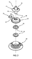
- FIG. 2 shows a top view of an exploded assembly of the fitment of this invention.
- Probe 10 is fitted into the inner circular opening 32 of cap 30 having flip lid 31 attached thereto by hinge 37.
- Hinge 37 fits into the recessed area 38 of cap 30 allowing flip lid 31 to recess into the inner circular opening 32 of cap 30 thereby providing a level and even surface to the top of cap 30 when flip lid 31 is in a closed position.
- Duckbill lock ring 23 is positioned between cap duckbill 20 and the top of spout 50 and locks into cap 30.
- FIG. 3 shows a side view of an exploded assembly of the fitment of FIG. 1 .
- the probe 10 which typically is a molded plastic part, has a nozzle 16 and a flange 11 molded to the nozzle 16 that presses against the cap 30.
- the flange 11 is reinforced with a flange-strengthening rib 12.
- a locking bead 13 is molded to flange strengthening rib 12 of the probe 10.
- the locking bead 13 of the probe 10 is attached to the cap 30 and forms a seal with the cap 30.
- the probe lead-in 15 need not have these product flow slots 14 and still be operative and allow for flow of fluid from the bag or container.
- the total length of the probe 10 is about 2.54 - 5.08 cm (1 to 2 inches), typically 3.56 cm (1.4 inches), and the nozzle 16 of the probe 10 is about 1.9 cm 0.75 inches.
- the outer diameter of the nozzle 16 of the probe is about 1.27 cm (0.5 inches).
- the diameter of the flange 11 that presses against the cap 30 depends on the width of the cap but typically is about 3.366 cm (1.325 inches).
- the thickness of the wall of the probe 10 is about 0.2413 cm (0.095 inch) in the nozzle section and about 0.127 cm (0.05 inch) at the seal at the edge of the flange 11.
- the above dimensions can vary depending on the liquid being dispensed.
- the inner diameter of the nozzle 16 of the probe 10 is about 0.635 cm (0.25 inch) and a variety of hoses typically can be attached to the nozzle 16.
- the hoses are attached to the nozzle 16 by a friction fit of the hose to the nozzle; however, other methods also can be used, such as, a hose clamp or the exterior of the nozzle may be provided with ribs or with a roughened surface for a better friction fit.
- the cap duckbill 20 is a molded elastomeric product or a soft flexible plastic material having a duckbill product flow opening 21. (See FIG. 1 also.)
- the duckbill seal 22 is fitted into the bottom of the probe 10 and engages with the inner wall of the nozzle 16.
- the duckbill product flow opening 21 (illustrated in FIG. 1 in a closed position) of the cap duckbill 20 typically is a re-closable opening, such as a slit in the cap duckbill 20 that allows fluid to flow from the bag or container upon engagement of the probe 10 by application of a downward force applied to the duckbill 20.
- the duckbill lock ring 23 prevents seepage of liquid through the product flow opening 21 until there is engagement by the probe 10.
- the product flow opening 21 of the cap duckbill 20 can be molded in such a manner that it would be broken open on engagement of probe 10.
- the product flow opening 21 can be sealed with a thin layer of material that is broken on engagement of the probe 10, or the opening itself can be sealed but breakable on engagement of the probe 10 and then re-sealable when the probe is disengaged.
- the duckbill seal 22 fits into cap 30 and forms a seal with inner circular opening 32 of the flip cap 30.
- the duckbill seal 22 can be permanently attached to the flip cap 30 by welding or heat sealing it to the cap 30.
- the primary advantage of the use of the cap duckbill 20 is to prevent back flow from the bag or container through the cap 30 when the probe 10 is not engaged and the hose attached to the probe 10 is removed.
- the cap duckbill shape as shown in FIG. 1 is preferred but other shapes can be used that would provide the same function.
- the length of the cap duckbill 20 is from about 0.95 - 2.54 cm (0.375 to 1.000 inch) and the width about 0.76 cm (0.3 inch), but these dimensions may vary depending on the design of the fitment.
- the cap duckbill 20 is molded from an elastomeric material or a soft flexible plastic material that can withstand the effects of the fluid being dispensed.
- elastomers are styrene/butadiene copolymers, butyl rubbers, polysulfide rubbers, polyisoprene, ethylene-propylene terpolymers (EPDM rubber), silicone rubbers, polyurethane rubbers, and the like.
- a soft flexible plastic material can also be used such a linear low molecular weight polyethylene or copolymers and blends thereof.
- the duckbill lock ring 23 also can be molded from any of the above materials, preferably, a plastic material, such as high density polyethylene or high density polypropylene.
- the flip cap 30 is a molded plastic part preferably formed of polyethylene but any of the aforementioned thermoplastics can be used.
- the flip cap 30 has attached to it a flip lid 31 by hinge 37 which can be moved and engaged with the opening of the flip cap 32 and forms a seal to retain liquid in the bag or container when the probe 10 is not inserted into or when it is removed from the opening of the flip cap 32.
- a seal of a thin film of plastic, coated paper, metal foil and the like can be sealed over the opening 32 of the flip cap to keep liquid product in the container or bag fresh and prevent spoilage. This seal can readily be removed, broken, or punctured at the time when product is to be removed from the container or bag.
- a pull tab 34 is molded to the flip lid 31 for easy opening and closing of the flip lid 31.
- the flip cap 30 has a handling flange 33 for holding the cap 30 while it is being moved over the spout 50 or removed there-from.
- the interior of the cap 30 fits over the sealing bead(s) 53 of the spout 50 to form liquid tight seal with the spout 50.
- the spout 50 also has a sealing flange 52 molded thereto and forms a liquid tight seal with the bag or container (not shown) when attached there-to.
- the flip lid 31 of the flip cap 30 is an optional feature and can be eliminated in particular when a seal is positioned over the opening 32 of the cap 30 and when the fitment is used only for an initial installation and the bag or container is not subsequently removed or closed after disengagement of the probe 10.
- the hinge 37 of the flip lid 31 can be recessed into a slot or recessed area 38 in the flip cap 30 to form a even surface on the on the flip lid 30.
- the recessed area 38 in the flip cap 30 is of a sufficient depth so that the flip lid 31 and the pull tab 34 are also recessed in the flip cap 30.
- FIG. 4 which is a cross sectional view of the assembly of the fitment (taken at line A-A' in FIG. 3 ) shows the positioning of the cap duckbill 20 in the flip cap 30 and the flip cap onto the spout 50.
- the flip cap 30 has two U-shaped collar openings: 35, which is the outer opening, and 36, which is the inner opening.
- the duckbill seal 22 of the cap duckbill 20 fits into the U-shaped collar opening 36 of the cap duckbill 20 and forms a seal.
- the flow opening 21 closes and seals and prevents further flow of any fluid from the bag.
- Duckbill lock ring 23 holds the flow opening 21 of the cap duckbill 20 closed until the probe 10 engages the cap duckbill 20 to allow flow of liquid and the top ring of the duckbill lock ring 23 fits into the inner opening 36 of the flip cap 30 and forms a seal with the flip cap 30.
- the flip cap 30 fits over the spout 50.
- the proximal end of the spout 50 fits into the outer U-shaped collar opening 35 of the flip cap 30 and a seal is formed with the spout seal beads 53 of the spout 50.
- Spout 50 is attached to a bag not shown via the molded sealing flange 52.
- the sealing flange 52 is heat sealed to the bag or container.
- the spout 50 has a handling flange 51 for ease of handling the fitment and the bag when attached.
- the spout 50 is molded from any of the aforementioned thermoplastic materials, although, polyethylene is preferred.
Landscapes
- Engineering & Computer Science (AREA)
- Mechanical Engineering (AREA)
- Closures For Containers (AREA)
- Packages (AREA)
- Bag Frames (AREA)
- Quick-Acting Or Multi-Walled Pipe Joints (AREA)
- Medical Preparation Storing Or Oral Administration Devices (AREA)
Claims (15)
- Zubehörteil zur Verwendung an einem zusammenklappbaren Beutel zum Ausgeben von Flüssigkeiten und halbfesten Materialien aus dem Beutel, wobei das Zubehörteil Folgendes umfasst:(a) eine Tülle (50), die einen im Allgemeinen hohlen zylindrischen Körper umfasst, welcher eine Außenfläche hat, die mit einer Kappe zusammenpasst, wobei die Tülle an einem Ende einen Basisabschnitt zum Befestigen der Tülle am zusammenklappbaren Beutel hat;(b) eine Kappe (30), die eine äußere Manschette (35) und eine innere Manschette (36) hat, wobei die äußere Manschette und die innere Manschette jeweils eine Innen- und Außenfläche haben, die Innenfläche der äußeren Manschette und die Außenfläche der inneren Manschette einen Hohlraum bilden, der zum lösbaren Befestigen an der Tülle ausgelegt ist, die Innenfläche der inneren Manschette an einem Kappen-Entenschnabel befestigt werden kann, die Kappe ferner einen hohlen Zylinderabschnitt umfasst, der ein proximales Ende und ein distales Ende hat, wobei jedes eine Innen- und Außenfläche hat, der Zylinderabschnitt an seinem distalen Ende an der inneren Manschette fest angeschlossen ist, die Innenfläche der inneren Manschette und die Außenfläche des proximalen Endes des Zylinders einen Hohlraum bilden;(c) eine gleitfähig abnehmbare Sonde (10);
dadurch gekennzeichnet, dass das Zubehörteil Folgendes umfasst:(d) einen im Wesentlichen hohlen Kappen-Entenschnabel (20), der dafür ausgelegt ist, sich mit dem proximalen Ende des hohlen Zylinderabschnitts der Kappe zu verbinden, und der eine Dichtung innerhalb des Zubehörteils bildet, die durch Einführen der Sonde in das Zubehörteil durch den hohlen Zylinder der Kappe geöffnet wird, wobei der Kappen-Entenschnabel ein konisches Ende und ein Ejektionsende hat, das konische Ende einen reversibel abdichtbaren Schlitz hat, der Fluid am Strömen durch die Kappe beim Entfernen der Sonde aus dem Zubehörteil hindern kann. - Zubehörteil nach Anspruch 1, wobei die Sonde einen im Allgemeinen hohlen zylindrischen Körper umfasst, der ein proximales Ende und ein distales Ende umfasst, wobei das distale Ende eine Düse (16) bildet, die einen Nippel hat, der sich mit einem Rohr verbinden kann, das proximale Ende eine Außenfläche hat, die zum Verbinden mit der Innenfläche des distalen Endes der Kappe ausgelegt ist, das proximale Ende ferner mindestens eine Vertiefung hat, die Fluid durch die Sonde strömen lässt, wenn die Haube, die durch den Entenschnabel der Kappendichtung gebildet wird, durch die Sonde kollabiert ist, das proximale Ende und das distale Ende durch einen Flansch auf der Außenfläche der Sonde getrennt sind, der sich um den Umfang der Sonde erstreckt, die Sonde bei Verbindung mit der Kappe die Haube der Kappendichtung zusammenfallen lässt, wodurch die Dichtung der Kappendichtung entfernt wird, so dass Fluid aus dem Beutel durch das Zubehörteil fließen kann, und die Sonde nach dem Entfernen aus der Verbindung mit der Kappe das Zusammenklappen der Haube der Kappendichtung aufhebt, wodurch die Kappendichtung wieder abgedichtet wird.
- Zubehörteil nach Anspruch 1 oder 2, das ferner einen im Wesentlichen hohlen Sonden-Entenschnabel umfasst, der zum Verbinden mit der Innenfläche der Sonde nahe dem proximalen Ende der Sonde ausgelegt ist, wobei der Sonden-Entenschnabel ein konisches Ende und ein Aufnahmeende hat, das konische Ende einen reversibel abdichtbaren Schlitz hat, der den Rückfluss von Fluid beim Entfernen des Rohres aus der Sonde verhindern kann, das Aufnahmeende in Fluidkommunikation mit dem Strom aus der Tülle ist, wenn die Dichtung zwischen der Kappe und der Kappendichtung entfernt wurde.
- Zubehörteil nach Anspruch 1, 2 oder 3, wobei die Kappe ferner einen Klappdeckel (31) umfasst, der mit der Kappe durch ein Scharnier (37) verbunden ist, welches dem Klappdeckel ermöglicht, sich zwischen einer geschlossenen Position an der Kappe, durch die der hohle Zylinderabschnitt abgedeckt wird, und einer offenen Position weg vom hohlen Zylinder zu bewegen.
- Zubehörteil nach Anspruch 4, wobei die Kappe und der Klappdeckel ein Mittel (13) zum Verriegeln des Klappdeckels in der geschlossenen Position auf der Kappe haben.
- Zubehörteil nach Anspruch 1, wobei die Kappe ferner eine entfernbare oder zerbrechliche weitere Dichtung umfasst, die das distale Ende der Kappe abdeckt.
- Zubehörteil nach Anspruch 6, wobei die zerbrechliche Dichtung durch die erste Einführung der Sonde (10) in den Zylinder der Kappe zerbrochen wird.
- Zubehörteil nach Anspruch 6, wobei die Dichtung ein dünnes Material umfasst, das aus der Gruppe bestehend aus Kunststoff, Papier oder Metallfolie ausgewählt ist.
- Zubehörteil nach Anspruch 1, wobei die Sonde eine Maschinensonde ist.
- Zubehörteil nach Anspruch 1, wobei der Kappen-Entenschnabel fest an der Innenfläche der Manschette der Kappe befestigt ist.
- Zubehörteil nach Anspruch 10, wobei der Kappen-Entenschnabel dadurch befestigt wird, dass er an die Manschette der Kappe angeschweißt oder heiß verklebt wird.
- Zubehörteil nach Anspruch 1, wobei der reversibel abgedichtete Schlitz des Entenschnabels dicht verschlossen ist und beim Aufstechen durch die Sonde geöffnet wird und dann beim Entfernen der Sonde sich wieder abdichtet.
- Zubehörteil nach Anspruch 4, wobei das Scharnier des Klappdeckels in der Kappe versenkt ist und dadurch dem Klappdeckel ermöglicht, in den Hohlraum in der Kappe versenkt zu werden.
- Zubehörteil nach Anspruch 1, das einen Entenschnabel-Verschlussring (23) im Eingriff mit dem Kappen-Entenschnabel hat, um das Fließen von Flüssigkeit aus dem Beutel zu verhindern, bis die Sonde in den Kappen-Entenschnabel eingreift.
- Zubehörteil nach Anspruch 1, wobei die Kappe einen Flansch (33) umfasst, die fest an die Außenfläche der äußeren Manschette angeschlossen ist.
Applications Claiming Priority (4)
| Application Number | Priority Date | Filing Date | Title |
|---|---|---|---|
| US14362209P | 2009-01-09 | 2009-01-09 | |
| US16288309P | 2009-03-24 | 2009-03-24 | |
| US16606509P | 2009-04-02 | 2009-04-02 | |
| PCT/US2010/020351 WO2010080897A1 (en) | 2009-01-09 | 2010-01-07 | Duckbill flip cap fitment for a collapsible container |
Publications (2)
| Publication Number | Publication Date |
|---|---|
| EP2386040A1 EP2386040A1 (de) | 2011-11-16 |
| EP2386040B1 true EP2386040B1 (de) | 2015-03-11 |
Family
ID=41571409
Family Applications (1)
| Application Number | Title | Priority Date | Filing Date |
|---|---|---|---|
| EP20100700088 Active EP2386040B1 (de) | 2009-01-09 | 2010-01-07 | Kappe und entenschnabelventil für einen weichen behälter |
Country Status (11)
| Country | Link |
|---|---|
| US (1) | US8413857B2 (de) |
| EP (1) | EP2386040B1 (de) |
| JP (1) | JP5655008B2 (de) |
| CN (2) | CN102308138B (de) |
| AU (1) | AU2010203591B2 (de) |
| CA (1) | CA2749308C (de) |
| CO (1) | CO6410252A2 (de) |
| ES (1) | ES2538472T3 (de) |
| MX (1) | MX2011007314A (de) |
| PL (1) | PL216609B1 (de) |
| WO (1) | WO2010080897A1 (de) |
Cited By (1)
| Publication number | Priority date | Publication date | Assignee | Title |
|---|---|---|---|---|
| WO2016198380A1 (en) | 2015-06-08 | 2016-12-15 | Nestec S.A. | Collapsible fluid dispensing package and valve fitment for dispensing fluid such as foodstuffs |
Families Citing this family (37)
| Publication number | Priority date | Publication date | Assignee | Title |
|---|---|---|---|---|
| DE102011080923A1 (de) * | 2011-08-12 | 2013-02-14 | Robert Bosch Gmbh | Kunststoffverschlussvorrichtung für Schlauchbeutel |
| USD679940S1 (en) | 2011-08-16 | 2013-04-16 | Glenn B. Paige | Fill cap for a drink container |
| US8931522B2 (en) * | 2011-08-16 | 2015-01-13 | Glenn B. Paige | Fill cap for a drink container |
| EP2751466B1 (de) * | 2011-08-29 | 2018-12-12 | Liqui-Box Corporation | Aseptischer einklappbarer entenschnabeleinsatz für einen zusammenklappbaren beutel und verfahren zum füllen eines zusammenklappbaren beutels |
| USD727730S1 (en) | 2012-03-23 | 2015-04-28 | S.C. Johnson & Son, Inc. | Cap |
| USD736634S1 (en) | 2012-03-23 | 2015-08-18 | S.C. Johnson & Son, Inc. | Container with cap |
| US8988228B2 (en) * | 2012-04-03 | 2015-03-24 | Swipesense, Inc. | Electronic module for tracking hand hygiene |
| BR112014029234B1 (pt) | 2012-05-25 | 2020-06-16 | Vitop Moulding S.R.L. | Sistema para o esvaziamento controlado de líquidos de recipientes |
| US9132238B2 (en) * | 2012-06-26 | 2015-09-15 | Becton, Dickinson And Company | Blow fill seal luer syringe |
| WO2014074220A1 (en) * | 2012-09-14 | 2014-05-15 | Illinois Tool Works Inc. | Access structure for a bag in a box container |
| JP6271574B2 (ja) * | 2012-11-29 | 2018-01-31 | インテグリス・インコーポレーテッド | キーコード付きの使い捨ての分配ヘッド |
| NO2951104T3 (de) * | 2013-02-04 | 2018-04-28 | ||
| GB2513840B (en) * | 2013-02-04 | 2015-08-05 | Mark Anthony Bradley | Container with irremovable closure to facilitate dispensation of contents |
| US9573736B2 (en) * | 2013-07-03 | 2017-02-21 | Scholle Ipn Corporation | Connector assembly for a self sealing fitment |
| JP6183017B2 (ja) * | 2013-07-10 | 2017-08-23 | 大日本印刷株式会社 | 注出口部材および注出口部材付き袋 |
| JP6183018B2 (ja) * | 2013-07-10 | 2017-08-23 | 大日本印刷株式会社 | 注出口部材および注出口部材付き袋 |
| GB201417128D0 (en) | 2014-09-29 | 2014-11-12 | Ds Smith Plastics Ltd | Dispensing assembly |
| US11027960B2 (en) * | 2015-08-13 | 2021-06-08 | David G. Kraenzle | Apparatus, systems, and methods relating to transfer of liquids to/from containers and/or storage of liquids in containers |
| US10005654B2 (en) | 2015-08-13 | 2018-06-26 | David G. Kraenzle | Apparatus, systems, and methods relating to transfer of fluids to/from containers and/or storage/transport of fluids in containers |
| US9827582B2 (en) | 2015-11-04 | 2017-11-28 | Ecolab Usa Inc. | Refillable dispensing systems and components |
| US10827659B2 (en) | 2015-11-29 | 2020-11-03 | Trong D Nguyen | Personal microwave autoclave and process using the same for sterilizing N95 masks |
| US9618130B1 (en) * | 2015-11-29 | 2017-04-11 | Trong D Nguyen | Multi-purpose valve for extending shelf-life using vacuuming or injecting gas |
| US10151396B2 (en) | 2015-11-29 | 2018-12-11 | Trong D Nguyen | Multi-purpose valve for vacuuming, de-vacuuming, gas injecting and pressure regulating |
| GB2549097A (en) * | 2016-04-04 | 2017-10-11 | Harding Edward | Tube closure |
| WO2017210151A1 (en) * | 2016-05-31 | 2017-12-07 | Carrier Commercial Refrigeration, Inc. | Valve assembly for a food product container of a food product dispensing machine |
| CN106122634B (zh) * | 2016-08-08 | 2019-05-07 | 张誉元 | 自闭锁快插接头及防脱落快速插接器 |
| CN109922665A (zh) * | 2016-10-11 | 2019-06-21 | 泰而勒商用食品服务公司 | 用于冷冻食品分配机器的软管配合组件和组装方法 |
| EP3687921A4 (de) * | 2017-09-27 | 2021-06-23 | Liqui-Box Corporation | Design einer leicht zu entfernenden kappe |
| US11117710B2 (en) * | 2017-12-04 | 2021-09-14 | Rapak, Llc | Valve assembly for bags |
| WO2020010295A1 (en) * | 2018-07-06 | 2020-01-09 | Liqui-Box Corporation | Dispensing probe for dispensing flowable material |
| US12179993B2 (en) * | 2019-06-14 | 2024-12-31 | Daizo Corporation | Discharge apparatus |
| CA3137852A1 (en) * | 2019-07-05 | 2021-01-14 | James W. Johnson | Probe |
| CN114761332B (zh) | 2020-03-12 | 2022-11-01 | Rlm集团有限公司 | 包括鸭嘴阀和防漏关闭机构的容器 |
| WO2021247697A1 (en) | 2020-06-02 | 2021-12-09 | RLM Group Ltd. | Sustainable packaging assemblies |
| AU2022240495B2 (en) * | 2021-03-16 | 2024-08-29 | Liqui-Box Corporation | Pierceable closure valve assembly |
| US12420992B2 (en) | 2022-05-05 | 2025-09-23 | Liqui-Box Corporation | Dispensing system |
| CN117282615B (zh) * | 2023-11-23 | 2024-02-02 | 苏州派特纳智能科技有限公司 | 一种防滴漏装置、石材养护药剂打膏机构和养护机器人 |
Family Cites Families (15)
| Publication number | Priority date | Publication date | Assignee | Title |
|---|---|---|---|---|
| USRE32354E (en) * | 1980-07-21 | 1987-02-17 | Scholle Corporation | Container for holding and dispensing fluid |
| US4436125A (en) * | 1982-03-17 | 1984-03-13 | Colder Products Company | Quick connect coupling |
| US5010925A (en) * | 1990-04-09 | 1991-04-30 | Vernay Laboratories, Inc. | Normally closed duckbill valve assembly |
| US5988705A (en) * | 1993-05-24 | 1999-11-23 | Pilot Industries, Inc. | Quick connect coupling |
| US5755269A (en) * | 1993-12-09 | 1998-05-26 | Ciba Corning Diagnostics Corp. | Fluid delivery system |
| JPH0735363U (ja) * | 1993-12-17 | 1995-06-27 | ドッドウエル・エンド・コムパニー・リミテッド | 液体収容バッグ |
| JP3270310B2 (ja) * | 1995-10-13 | 2002-04-02 | キッコーマン株式会社 | バッグインボックスの封入液注出装置 |
| US6044859A (en) * | 1997-03-03 | 2000-04-04 | Filtertek Inc | Valve apparatus and method |
| JP4605568B2 (ja) * | 2000-11-24 | 2011-01-05 | 大日本印刷株式会社 | バッグインボックス用充填口 |
| JP4401038B2 (ja) * | 2001-05-30 | 2010-01-20 | 株式会社吉野工業所 | スリットバルブ付きキャップ |
| US7404542B2 (en) * | 2004-02-13 | 2008-07-29 | Rapak, Llc | Valve for a flexible container |
| WO2007059083A2 (en) * | 2005-11-10 | 2007-05-24 | International Dispensing Corporation | Dispensing valve for fluids stored under pressure |
| US20070267451A1 (en) * | 2006-05-17 | 2007-11-22 | Owens-Illinois Closure Inc. | Dispensing closure, closure and container package, and method of manufacture |
| MX354654B (es) * | 2006-08-28 | 2018-03-14 | Liqui Box Canada Inc | Montaje y collar de válvula de corredera. |
| US8070014B2 (en) * | 2007-08-24 | 2011-12-06 | Seaquist Closures L.L.C. | Liner piercing twist closure |
-
2010
- 2010-01-07 WO PCT/US2010/020351 patent/WO2010080897A1/en not_active Ceased
- 2010-01-07 PL PL397212A patent/PL216609B1/pl unknown
- 2010-01-07 CN CN2010800070502A patent/CN102308138B/zh not_active Expired - Fee Related
- 2010-01-07 AU AU2010203591A patent/AU2010203591B2/en active Active
- 2010-01-07 EP EP20100700088 patent/EP2386040B1/de active Active
- 2010-01-07 MX MX2011007314A patent/MX2011007314A/es active IP Right Grant
- 2010-01-07 CN CN201310301818.2A patent/CN103538778B/zh not_active Expired - Fee Related
- 2010-01-07 US US12/683,865 patent/US8413857B2/en active Active
- 2010-01-07 CA CA2749308A patent/CA2749308C/en active Active
- 2010-01-07 JP JP2011545424A patent/JP5655008B2/ja active Active
- 2010-01-07 ES ES10700088.7T patent/ES2538472T3/es active Active
-
2011
- 2011-08-02 CO CO11097384A patent/CO6410252A2/es active IP Right Grant
Cited By (1)
| Publication number | Priority date | Publication date | Assignee | Title |
|---|---|---|---|---|
| WO2016198380A1 (en) | 2015-06-08 | 2016-12-15 | Nestec S.A. | Collapsible fluid dispensing package and valve fitment for dispensing fluid such as foodstuffs |
Also Published As
| Publication number | Publication date |
|---|---|
| CN102308138A (zh) | 2012-01-04 |
| CA2749308A1 (en) | 2010-07-15 |
| US20100176152A1 (en) | 2010-07-15 |
| WO2010080897A1 (en) | 2010-07-15 |
| AU2010203591A1 (en) | 2011-07-21 |
| MX2011007314A (es) | 2011-08-12 |
| CN103538778A (zh) | 2014-01-29 |
| PL216609B1 (pl) | 2014-04-30 |
| EP2386040A1 (de) | 2011-11-16 |
| CO6410252A2 (es) | 2012-03-30 |
| PL397212A1 (pl) | 2012-06-04 |
| CA2749308C (en) | 2018-01-09 |
| HK1163782A1 (en) | 2012-09-14 |
| JP2012514567A (ja) | 2012-06-28 |
| CN103538778B (zh) | 2016-08-10 |
| CN102308138B (zh) | 2013-08-14 |
| AU2010203591B2 (en) | 2015-10-08 |
| US8413857B2 (en) | 2013-04-09 |
| ES2538472T3 (es) | 2015-06-22 |
| JP5655008B2 (ja) | 2015-01-14 |
Similar Documents
| Publication | Publication Date | Title |
|---|---|---|
| US8413857B2 (en) | Duckbill flip cap fitment for a collapsible container | |
| EP2751466B1 (de) | Aseptischer einklappbarer entenschnabeleinsatz für einen zusammenklappbaren beutel und verfahren zum füllen eines zusammenklappbaren beutels | |
| EP2385919B1 (de) | Tellerdichtungsansatz für einen zusammenfaltbaren beutel | |
| US5467806A (en) | Two-part coupling structure having cooperating parts effecting fluid flow upon connection an mutual resealing upon disconnection | |
| ES2676579T3 (es) | Conjunto de válvula de corredera para envase aséptico | |
| US11142377B2 (en) | Easy to remove cap design | |
| HK1163782B (en) | Duckbill flip cap fitment for a collapsible container | |
| RU2506486C2 (ru) | Укупорочное средство с откидным колпачком и клапаном утиный нос для сжимаемой емкости |
Legal Events
| Date | Code | Title | Description |
|---|---|---|---|
| PUAI | Public reference made under article 153(3) epc to a published international application that has entered the european phase |
Free format text: ORIGINAL CODE: 0009012 |
|
| 17P | Request for examination filed |
Effective date: 20110803 |
|
| AK | Designated contracting states |
Kind code of ref document: A1 Designated state(s): AT BE BG CH CY CZ DE DK EE ES FI FR GB GR HR HU IE IS IT LI LT LU LV MC MK MT NL NO PL PT RO SE SI SK SM TR |
|
| DAX | Request for extension of the european patent (deleted) | ||
| REG | Reference to a national code |
Ref country code: HK Ref legal event code: DE Ref document number: 1163782 Country of ref document: HK |
|
| GRAP | Despatch of communication of intention to grant a patent |
Free format text: ORIGINAL CODE: EPIDOSNIGR1 |
|
| GRAJ | Information related to disapproval of communication of intention to grant by the applicant or resumption of examination proceedings by the epo deleted |
Free format text: ORIGINAL CODE: EPIDOSDIGR1 |
|
| GRAP | Despatch of communication of intention to grant a patent |
Free format text: ORIGINAL CODE: EPIDOSNIGR1 |
|
| INTG | Intention to grant announced |
Effective date: 20140919 |
|
| INTG | Intention to grant announced |
Effective date: 20140930 |
|
| GRAS | Grant fee paid |
Free format text: ORIGINAL CODE: EPIDOSNIGR3 |
|
| GRAA | (expected) grant |
Free format text: ORIGINAL CODE: 0009210 |
|
| AK | Designated contracting states |
Kind code of ref document: B1 Designated state(s): AT BE BG CH CY CZ DE DK EE ES FI FR GB GR HR HU IE IS IT LI LT LU LV MC MK MT NL NO PL PT RO SE SI SK SM TR |
|
| REG | Reference to a national code |
Ref country code: GB Ref legal event code: FG4D |
|
| REG | Reference to a national code |
Ref country code: CH Ref legal event code: EP |
|
| REG | Reference to a national code |
Ref country code: IE Ref legal event code: FG4D |
|
| REG | Reference to a national code |
Ref country code: AT Ref legal event code: REF Ref document number: 715548 Country of ref document: AT Kind code of ref document: T Effective date: 20150415 |
|
| REG | Reference to a national code |
Ref country code: DE Ref legal event code: R096 Ref document number: 602010023008 Country of ref document: DE Effective date: 20150423 |
|
| REG | Reference to a national code |
Ref country code: ES Ref legal event code: FG2A Ref document number: 2538472 Country of ref document: ES Kind code of ref document: T3 Effective date: 20150622 |
|
| REG | Reference to a national code |
Ref country code: NL Ref legal event code: VDEP Effective date: 20150311 |
|
| REG | Reference to a national code |
Ref country code: NL Ref legal event code: VDEP Effective date: 20150311 |
|
| PG25 | Lapsed in a contracting state [announced via postgrant information from national office to epo] |
Ref country code: LT Free format text: LAPSE BECAUSE OF FAILURE TO SUBMIT A TRANSLATION OF THE DESCRIPTION OR TO PAY THE FEE WITHIN THE PRESCRIBED TIME-LIMIT Effective date: 20150311 Ref country code: SE Free format text: LAPSE BECAUSE OF FAILURE TO SUBMIT A TRANSLATION OF THE DESCRIPTION OR TO PAY THE FEE WITHIN THE PRESCRIBED TIME-LIMIT Effective date: 20150311 Ref country code: HR Free format text: LAPSE BECAUSE OF FAILURE TO SUBMIT A TRANSLATION OF THE DESCRIPTION OR TO PAY THE FEE WITHIN THE PRESCRIBED TIME-LIMIT Effective date: 20150311 Ref country code: NO Free format text: LAPSE BECAUSE OF FAILURE TO SUBMIT A TRANSLATION OF THE DESCRIPTION OR TO PAY THE FEE WITHIN THE PRESCRIBED TIME-LIMIT Effective date: 20150611 Ref country code: FI Free format text: LAPSE BECAUSE OF FAILURE TO SUBMIT A TRANSLATION OF THE DESCRIPTION OR TO PAY THE FEE WITHIN THE PRESCRIBED TIME-LIMIT Effective date: 20150311 |
|
| REG | Reference to a national code |
Ref country code: LT Ref legal event code: MG4D |
|
| PG25 | Lapsed in a contracting state [announced via postgrant information from national office to epo] |
Ref country code: LV Free format text: LAPSE BECAUSE OF FAILURE TO SUBMIT A TRANSLATION OF THE DESCRIPTION OR TO PAY THE FEE WITHIN THE PRESCRIBED TIME-LIMIT Effective date: 20150311 Ref country code: GR Free format text: LAPSE BECAUSE OF FAILURE TO SUBMIT A TRANSLATION OF THE DESCRIPTION OR TO PAY THE FEE WITHIN THE PRESCRIBED TIME-LIMIT Effective date: 20150612 |
|
| PG25 | Lapsed in a contracting state [announced via postgrant information from national office to epo] |
Ref country code: NL Free format text: LAPSE BECAUSE OF FAILURE TO SUBMIT A TRANSLATION OF THE DESCRIPTION OR TO PAY THE FEE WITHIN THE PRESCRIBED TIME-LIMIT Effective date: 20150311 |
|
| PG25 | Lapsed in a contracting state [announced via postgrant information from national office to epo] |
Ref country code: SK Free format text: LAPSE BECAUSE OF FAILURE TO SUBMIT A TRANSLATION OF THE DESCRIPTION OR TO PAY THE FEE WITHIN THE PRESCRIBED TIME-LIMIT Effective date: 20150311 Ref country code: CZ Free format text: LAPSE BECAUSE OF FAILURE TO SUBMIT A TRANSLATION OF THE DESCRIPTION OR TO PAY THE FEE WITHIN THE PRESCRIBED TIME-LIMIT Effective date: 20150311 Ref country code: RO Free format text: LAPSE BECAUSE OF FAILURE TO SUBMIT A TRANSLATION OF THE DESCRIPTION OR TO PAY THE FEE WITHIN THE PRESCRIBED TIME-LIMIT Effective date: 20150311 Ref country code: PT Free format text: LAPSE BECAUSE OF FAILURE TO SUBMIT A TRANSLATION OF THE DESCRIPTION OR TO PAY THE FEE WITHIN THE PRESCRIBED TIME-LIMIT Effective date: 20150713 Ref country code: EE Free format text: LAPSE BECAUSE OF FAILURE TO SUBMIT A TRANSLATION OF THE DESCRIPTION OR TO PAY THE FEE WITHIN THE PRESCRIBED TIME-LIMIT Effective date: 20150311 |
|
| PG25 | Lapsed in a contracting state [announced via postgrant information from national office to epo] |
Ref country code: PL Free format text: LAPSE BECAUSE OF FAILURE TO SUBMIT A TRANSLATION OF THE DESCRIPTION OR TO PAY THE FEE WITHIN THE PRESCRIBED TIME-LIMIT Effective date: 20150311 Ref country code: IS Free format text: LAPSE BECAUSE OF FAILURE TO SUBMIT A TRANSLATION OF THE DESCRIPTION OR TO PAY THE FEE WITHIN THE PRESCRIBED TIME-LIMIT Effective date: 20150711 |
|
| REG | Reference to a national code |
Ref country code: DE Ref legal event code: R097 Ref document number: 602010023008 Country of ref document: DE |
|
| REG | Reference to a national code |
Ref country code: HK Ref legal event code: GR Ref document number: 1163782 Country of ref document: HK |
|
| REG | Reference to a national code |
Ref country code: FR Ref legal event code: PLFP Year of fee payment: 7 |
|
| PG25 | Lapsed in a contracting state [announced via postgrant information from national office to epo] |
Ref country code: IT Free format text: LAPSE BECAUSE OF FAILURE TO SUBMIT A TRANSLATION OF THE DESCRIPTION OR TO PAY THE FEE WITHIN THE PRESCRIBED TIME-LIMIT Effective date: 20150311 |
|
| PLBE | No opposition filed within time limit |
Free format text: ORIGINAL CODE: 0009261 |
|
| STAA | Information on the status of an ep patent application or granted ep patent |
Free format text: STATUS: NO OPPOSITION FILED WITHIN TIME LIMIT |
|
| PG25 | Lapsed in a contracting state [announced via postgrant information from national office to epo] |
Ref country code: DK Free format text: LAPSE BECAUSE OF FAILURE TO SUBMIT A TRANSLATION OF THE DESCRIPTION OR TO PAY THE FEE WITHIN THE PRESCRIBED TIME-LIMIT Effective date: 20150311 |
|
| 26N | No opposition filed |
Effective date: 20151214 |
|
| PG25 | Lapsed in a contracting state [announced via postgrant information from national office to epo] |
Ref country code: SI Free format text: LAPSE BECAUSE OF FAILURE TO SUBMIT A TRANSLATION OF THE DESCRIPTION OR TO PAY THE FEE WITHIN THE PRESCRIBED TIME-LIMIT Effective date: 20150311 |
|
| PG25 | Lapsed in a contracting state [announced via postgrant information from national office to epo] |
Ref country code: LU Free format text: LAPSE BECAUSE OF FAILURE TO SUBMIT A TRANSLATION OF THE DESCRIPTION OR TO PAY THE FEE WITHIN THE PRESCRIBED TIME-LIMIT Effective date: 20160107 |
|
| REG | Reference to a national code |
Ref country code: CH Ref legal event code: PL |
|
| PG25 | Lapsed in a contracting state [announced via postgrant information from national office to epo] |
Ref country code: MC Free format text: LAPSE BECAUSE OF FAILURE TO SUBMIT A TRANSLATION OF THE DESCRIPTION OR TO PAY THE FEE WITHIN THE PRESCRIBED TIME-LIMIT Effective date: 20150311 |
|
| REG | Reference to a national code |
Ref country code: AT Ref legal event code: UEP Ref document number: 715548 Country of ref document: AT Kind code of ref document: T Effective date: 20150311 |
|
| PG25 | Lapsed in a contracting state [announced via postgrant information from national office to epo] |
Ref country code: LI Free format text: LAPSE BECAUSE OF NON-PAYMENT OF DUE FEES Effective date: 20160131 Ref country code: CH Free format text: LAPSE BECAUSE OF NON-PAYMENT OF DUE FEES Effective date: 20160131 |
|
| REG | Reference to a national code |
Ref country code: IE Ref legal event code: MM4A |
|
| REG | Reference to a national code |
Ref country code: FR Ref legal event code: PLFP Year of fee payment: 8 |
|
| PG25 | Lapsed in a contracting state [announced via postgrant information from national office to epo] |
Ref country code: IE Free format text: LAPSE BECAUSE OF NON-PAYMENT OF DUE FEES Effective date: 20160107 |
|
| PG25 | Lapsed in a contracting state [announced via postgrant information from national office to epo] |
Ref country code: MT Free format text: LAPSE BECAUSE OF FAILURE TO SUBMIT A TRANSLATION OF THE DESCRIPTION OR TO PAY THE FEE WITHIN THE PRESCRIBED TIME-LIMIT Effective date: 20150311 |
|
| REG | Reference to a national code |
Ref country code: FR Ref legal event code: PLFP Year of fee payment: 9 |
|
| PG25 | Lapsed in a contracting state [announced via postgrant information from national office to epo] |
Ref country code: HU Free format text: LAPSE BECAUSE OF FAILURE TO SUBMIT A TRANSLATION OF THE DESCRIPTION OR TO PAY THE FEE WITHIN THE PRESCRIBED TIME-LIMIT; INVALID AB INITIO Effective date: 20100107 Ref country code: SM Free format text: LAPSE BECAUSE OF FAILURE TO SUBMIT A TRANSLATION OF THE DESCRIPTION OR TO PAY THE FEE WITHIN THE PRESCRIBED TIME-LIMIT Effective date: 20150311 Ref country code: CY Free format text: LAPSE BECAUSE OF FAILURE TO SUBMIT A TRANSLATION OF THE DESCRIPTION OR TO PAY THE FEE WITHIN THE PRESCRIBED TIME-LIMIT Effective date: 20150311 |
|
| PG25 | Lapsed in a contracting state [announced via postgrant information from national office to epo] |
Ref country code: TR Free format text: LAPSE BECAUSE OF FAILURE TO SUBMIT A TRANSLATION OF THE DESCRIPTION OR TO PAY THE FEE WITHIN THE PRESCRIBED TIME-LIMIT Effective date: 20150311 Ref country code: MT Free format text: LAPSE BECAUSE OF FAILURE TO SUBMIT A TRANSLATION OF THE DESCRIPTION OR TO PAY THE FEE WITHIN THE PRESCRIBED TIME-LIMIT Effective date: 20160131 Ref country code: MK Free format text: LAPSE BECAUSE OF FAILURE TO SUBMIT A TRANSLATION OF THE DESCRIPTION OR TO PAY THE FEE WITHIN THE PRESCRIBED TIME-LIMIT Effective date: 20150311 |
|
| PG25 | Lapsed in a contracting state [announced via postgrant information from national office to epo] |
Ref country code: BG Free format text: LAPSE BECAUSE OF FAILURE TO SUBMIT A TRANSLATION OF THE DESCRIPTION OR TO PAY THE FEE WITHIN THE PRESCRIBED TIME-LIMIT Effective date: 20150311 |
|
| REG | Reference to a national code |
Ref country code: DE Ref legal event code: R082 Ref document number: 602010023008 Country of ref document: DE |
|
| P01 | Opt-out of the competence of the unified patent court (upc) registered |
Effective date: 20230518 |
|
| PGFP | Annual fee paid to national office [announced via postgrant information from national office to epo] |
Ref country code: GB Payment date: 20260126 Year of fee payment: 17 |
|
| PGFP | Annual fee paid to national office [announced via postgrant information from national office to epo] |
Ref country code: ES Payment date: 20260210 Year of fee payment: 17 |
|
| PGFP | Annual fee paid to national office [announced via postgrant information from national office to epo] |
Ref country code: DE Payment date: 20260127 Year of fee payment: 17 |
|
| PGFP | Annual fee paid to national office [announced via postgrant information from national office to epo] |
Ref country code: AT Payment date: 20260119 Year of fee payment: 17 |
|
| PGFP | Annual fee paid to national office [announced via postgrant information from national office to epo] |
Ref country code: BE Payment date: 20260123 Year of fee payment: 17 |
|
| PGFP | Annual fee paid to national office [announced via postgrant information from national office to epo] |
Ref country code: FR Payment date: 20260126 Year of fee payment: 17 |