EP2386508A2 - Appareil de transport de papier, appareil d'alimentation en papier et appareil de formation d'image - Google Patents
Appareil de transport de papier, appareil d'alimentation en papier et appareil de formation d'image Download PDFInfo
- Publication number
- EP2386508A2 EP2386508A2 EP11164440A EP11164440A EP2386508A2 EP 2386508 A2 EP2386508 A2 EP 2386508A2 EP 11164440 A EP11164440 A EP 11164440A EP 11164440 A EP11164440 A EP 11164440A EP 2386508 A2 EP2386508 A2 EP 2386508A2
- Authority
- EP
- European Patent Office
- Prior art keywords
- paper
- roller shaft
- cover member
- roller
- transport
- Prior art date
- Legal status (The legal status is an assumption and is not a legal conclusion. Google has not performed a legal analysis and makes no representation as to the accuracy of the status listed.)
- Withdrawn
Links
Images




Classifications
-
- G—PHYSICS
- G03—PHOTOGRAPHY; CINEMATOGRAPHY; ANALOGOUS TECHNIQUES USING WAVES OTHER THAN OPTICAL WAVES; ELECTROGRAPHY; HOLOGRAPHY
- G03G—ELECTROGRAPHY; ELECTROPHOTOGRAPHY; MAGNETOGRAPHY
- G03G15/00—Apparatus for electrographic processes using a charge pattern
-
- B—PERFORMING OPERATIONS; TRANSPORTING
- B65—CONVEYING; PACKING; STORING; HANDLING THIN OR FILAMENTARY MATERIAL
- B65H—HANDLING THIN OR FILAMENTARY MATERIAL, e.g. SHEETS, WEBS, CABLES
- B65H5/00—Feeding articles separated from piles; Feeding articles to machines
- B65H5/06—Feeding articles separated from piles; Feeding articles to machines by rollers or balls, e.g. between rollers
- B65H5/062—Feeding articles separated from piles; Feeding articles to machines by rollers or balls, e.g. between rollers between rollers or balls
-
- B—PERFORMING OPERATIONS; TRANSPORTING
- B41—PRINTING; LINING MACHINES; TYPEWRITERS; STAMPS
- B41J—TYPEWRITERS; SELECTIVE PRINTING MECHANISMS, i.e. MECHANISMS PRINTING OTHERWISE THAN FROM A FORME; CORRECTION OF TYPOGRAPHICAL ERRORS
- B41J13/00—Devices or arrangements of selective printing mechanisms, e.g. ink-jet printers or thermal printers, specially adapted for supporting or handling copy material in short lengths, e.g. sheets
-
- B—PERFORMING OPERATIONS; TRANSPORTING
- B65—CONVEYING; PACKING; STORING; HANDLING THIN OR FILAMENTARY MATERIAL
- B65H—HANDLING THIN OR FILAMENTARY MATERIAL, e.g. SHEETS, WEBS, CABLES
- B65H2402/00—Constructional details of the handling apparatus
- B65H2402/40—Details of frames, housings or mountings of the whole handling apparatus
- B65H2402/44—Housings
- B65H2402/441—Housings movable for facilitating access to area inside the housing, e.g. pivoting or sliding
-
- B—PERFORMING OPERATIONS; TRANSPORTING
- B65—CONVEYING; PACKING; STORING; HANDLING THIN OR FILAMENTARY MATERIAL
- B65H—HANDLING THIN OR FILAMENTARY MATERIAL, e.g. SHEETS, WEBS, CABLES
- B65H2404/00—Parts for transporting or guiding the handled material
- B65H2404/10—Rollers
- B65H2404/13—Details of longitudinal profile
- B65H2404/134—Axle
- B65H2404/1341—Elastic mounting, i.e. subject to biasing means
-
- B—PERFORMING OPERATIONS; TRANSPORTING
- B65—CONVEYING; PACKING; STORING; HANDLING THIN OR FILAMENTARY MATERIAL
- B65H—HANDLING THIN OR FILAMENTARY MATERIAL, e.g. SHEETS, WEBS, CABLES
- B65H2404/00—Parts for transporting or guiding the handled material
- B65H2404/10—Rollers
- B65H2404/14—Roller pairs
- B65H2404/144—Roller pairs with relative movement of the rollers to / from each other
-
- B—PERFORMING OPERATIONS; TRANSPORTING
- B65—CONVEYING; PACKING; STORING; HANDLING THIN OR FILAMENTARY MATERIAL
- B65H—HANDLING THIN OR FILAMENTARY MATERIAL, e.g. SHEETS, WEBS, CABLES
- B65H2404/00—Parts for transporting or guiding the handled material
- B65H2404/60—Other elements in face contact with handled material
- B65H2404/61—Longitudinally-extending strips, tubes, plates, or wires
- B65H2404/611—Longitudinally-extending strips, tubes, plates, or wires arranged to form a channel
Definitions
- the present invention relates to a paper transporting apparatus, a paper feeding unit including the paper transporting apparatus, and an image forming apparatus including the paper feeding unit.
- An image forming apparatus such as a printer, a facsimile device, and a copier, includes a paper feeding apparatus configured to feed paper from a paper feed cassette to an image forming unit.
- a paper feeding apparatus generally includes a pair of transport rollers arranged above the sides of the paper feed cassette, and paper in the paper feed cassette are transported to the image forming unit by the pair of transport rollers.
- a paper feeding apparatus with a more specific configuration will be described.
- an open-close cover which covers the pair of transport rollers is provided, and a roller shaft which supports one of the pair of transport rollers is attached to the open-close cover.
- Another roller shaft which supports the other of the pair of transport rollers is attached to a main body of the paper feeding apparatus. Since the transport rollers are separated from each other when the open-close cover is opened, paper jammed near the pair of transport rollers can be removed.
- preferred embodiments of the present invention provide a paper transporting apparatus which can maintain an adequate transport force from the pair of transport rollers, even if the cover member to which one of the pair of transport rollers is attached cambers.
- the present invention also provides a paper feeding unit including the paper transporting apparatus and an image forming apparatus including the paper feeding unit.
- a paper transporting apparatus includes a pair of transport rollers, a first roller shaft, a second roller shaft, a cover member, and an urging member.
- the pair of transport rollers includes a first transport roller and a second transport roller opposed to the first transport roller, and transports paper.
- the first roller shaft is inserted through the first transport roller, and the second roller shaft is inserted through the second transport roller.
- the cover member can be opened and closed.
- the urging member is attached to the inner face of the cover member, and supports the second roller shaft. The urging member urges the second roller shaft toward the first roller shaft when the cover member is closed.
- paper is transported by the first and the second transport rollers which are attached respectively to the first and the second roller shafts.
- the urging member attached to the inner face of the cover member supports the second roller shaft, and urges the second roller shaft toward the first roller shaft when the cover member is closed.
- the second roller shaft which is not directly attached to the cover member, is supported by the urging member attached to the cover member and is urged toward the first roller shaft. Consequently, even if the cover member cambers outward, separation of the second roller from the first roller following the camber of the cover member can be prevented, and the nip force from the first and the second transport rollers therefore can be maintained. As a result, adequate transport force from the pair of transport rollers can be maintained even if the cover member, to which one of the pair of transport rollers is attached, cambers.
- the paper feeding unit includes a storage unit and a paper transporting apparatus.
- the storage unit contains paper.
- the paper transporting apparatus transports paper from the storage unit.
- the paper transporting apparatus includes a pair of transport rollers, a first roller shaft, a second roller shaft, a cover member, and an urging member.
- the pair of transport rollers includes a first transport roller and a second transport roller opposed to the first transport roller, and transports paper.
- the first roller shaft is inserted through the first transport roller.
- the second roller shaft is inserted through the second transport roller.
- the cover member can be opened and closed.
- the urging member attached to the inner face of the cover member, supports the second roller shaft, and urges the second roller shaft towards the first roller shaft when the cover member is closed.
- the paper feeding unit according to the present invention can maintain adequate transport force from the pair of transport rollers so as to transport paper from the storage unit even if the cover member, to which one of the pair of transport rollers is attached, cambers.
- An image forming apparatus includes an image forming unit, a storage unit, and a paper transporting apparatus.
- the image forming unit forms an image on paper.
- the storage unit contains paper.
- the paper transporting apparatus transports paper from the storage unit to the image forming unit.
- the paper transporting apparatus includes a pair of transport rollers, a first roller shaft, a second roller shaft, a cover member, and an urging member.
- the pair of transport rollers includes a first transport roller and a second transport roller opposed to the first transport roller, and transports the paper.
- the first roller shaft is inserted through the first transport roller.
- the second roller shaft is inserted through the second transport roller.
- the cover member can be opened and closed.
- the urging member attached to the inner face of the cover member supports the second roller shaft, and urges the second roller shaft towards the first roller shaft when the cover member is closed.
- the image forming apparatus can maintain adequate transport force from the pair of transport rollers so as to transport paper from the storage unit to the image forming unit even if the cover member, to which one of the pair of transport rollers is attached, cambers.
- the cover member is formed into a substantially rectangular shape and includes a base end section that serves as an axis of rotation for opening and closing the cover member, and that the base end section of the urging member is attached to the side of the base end section of the cover member, and the head section of the urging member is located on the side of the head section of the cover member to support the second roller shaft and urge the second roller shaft towards the first roller shaft when the cover member is closed.
- the base end section of the urging member is attached to the side of the base end section of the cover member, where relatively less camber occurs, and the head section of the urging member is located on the side of the head section of the cover member to support the second roller shaft and urge the second roller shaft towards the first roller shaft. Consequently, the base end section of the urging member is less affected by the camber of the head section of the cover member, where the camber occurs relatively frequently, thereby ensuring the state in which the second roller shaft is urged towards the first roller shaft.
- the urging member is a leaf spring.
- the second roller shaft can be urged with a relatively easy configuration.
- the cover member is made of resin. It is further preferable that the cover member is made of acrylonitrile butadiene styrene copolymer (ABS).
- Fig. 1 is a cross section view of a multifunction peripheral according to an embodiment of the image forming apparatus of an embodiment of the present invention.
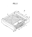
- Fig. 2 is an external perspective view of the paper feeding unit according to the embodiment, included in the multifunction peripheral.
- Fig. 3 is a perspective view of the paper transporting apparatus according to the embodiment, included in the paper feeding unit.
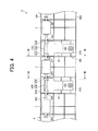
- Fig. 4 is a drawing illustrating a configuration of a cover unit included in the paper transporting apparatus.
- Fig. 5 is a perspective view of the urging member included in the paper transporting apparatus.
- Fig. 6 is a side view of the urging member included in the paper transporting apparatus.
- Fig. 7 is a cross section view of Fig. 4 along the line VII-VII.
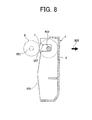
- Fig. 8 is a cross section view of Fig. 4 along the line VIII-VIII.
- a general configuration of a multifunction peripheral 1 according to an embodiment of the image forming apparatus of the present invention will be described with reference to Fig. 1.
- Fig. 1 is a cross section view of the multifunction peripheral 1.
- the multifunction peripheral 1 includes a paper transporting apparatus 3 according to the embodiment of the present invention.
- the multifunction peripheral 1 includes a print function which prints an image on paper, and also functions as a copier, a scanner, and a facsimile device.
- the paper transporting apparatus 3 of the multifunction peripheral 1 is configured to maintain an adequate transport force from a driven roller 7 and a driving roller 6 opposed to the driven roller 7, even if an open-close cover 5 to which the driven roller 7 is attached cambers outward after several years of use.
- the multifunction peripheral 1 includes an image reading unit 9 arranged in the upper part of the main body of the multifunction peripheral 1, a paper feeding section 11 arranged in the lower part of the main body of the multifunction peripheral 1, and an image forming unit 13 arranged above the paper feeding section 11.
- the image reading unit 9 includes a document tray 15 arranged at the top, and documents placed on the document tray 15 are passed through a reading position 19 and then ejected to a document eject tray 21 by an automatic document feeder (ADF) 17.
- ADF automatic document feeder
- the documents placed on the document tray 15 are picked up by a pick up roller 23, separated one by one by a separate pad 25, and then transported to a driving roller 27.
- Two driven rollers 29, 31 are arranged on the driving roller 27, and each document is transported through a curved transport path along the periphery of the driving roller 27 to the reading position 19 arranged below the driving roller 27.
- the document is read by a reading apparatus 33 arranged below the reading position 19, and then ejected to the document eject tray 21 by a pair of eject rollers 35.
- document data read by the reading apparatus 33 is printed on paper by the image forming unit 13.
- the image forming unit 13 When performing a printing process, paper fed from the paper feeding section 11 is transported to the image forming unit 13 at a predetermined time after being registered by a pair of registration rollers 39.
- the image forming unit 13 forms an image on paper with an electrographic method.
- the image forming unit 13 includes a transferring unit 41 and a fixing unit 43, both of which are arranged along the transport path.
- the transferring unit 41 includes a charged roller 47, an LED unit 49, a develop roller 51, and a transfer roller 53, all of which are arranged around a photoreceptor drum 45.
- an electrostatic latent image is formed on the photoreceptor drum 45 by the LED unit 49 after the photoreceptor drum 45 has been homogeneously charged by the charged roller 47.
- Toner is transported from the develop roller 51, which contains the toner in a toner room 55, onto the electrostatic latent image on the photoreceptor drum 45, thereby forming a toner image on the photoreceptor drum 45. And then, the transported paper is nipped through the photoreceptor drum 45 and the transfer roller 53 with a voltage applied, thereby transferring the toner image on the photoreceptor drum 45 onto paper.
- the fixing unit 43 includes a heat roller 57 and a press roller 59.
- a heat roller 57 and a press roller 59 By nipping the paper, on which the toner image has been transferred, with the heat roller 57 and the press roller 59, the paper on which the toner image has been formed is heated and pressured, thereby fixing the toner on the paper to complete the printing process.
- the paper on which the image has been printed is then ejected to the eject tray 63 by an eject roller 61.
- the paper feeding section 11 includes a paper cassette 65 which contains paper, and a pair of paper feed rollers 67 that feed the paper from the paper cassette 65.
- the paper cassette 65 is formed into a substantially rectangular parallelepiped.
- a lifting board 73 is arranged in the paper cassette 65 and has an end portion near an end face of the paper cassette 65. The end portion of the lifting board 73 is urged upward by a spring (not illustrated). Accordingly, paper placed on the lifting board 73 would be in a state in which an end of the paper is pressed against a pick up roller 75 arranged on the upper part of the end face of the paper cassette 65.
- the pair of paper feed rollers 67 includes a driving roller 79 arranged on the side of the paper cassette 65, and a driven roller 81 opposed to the driving roller 79.
- the driven roller 81 is attached to an open-close cover 83 attached to the side of the main body of the multifunction peripheral 1.
- the open-close cover 83 is attached to the main body of the multifunction peripheral 1 in a way that it may be opened and closed around an axis of a hinge pin 85, and the driven roller 81 is attached to the inner face of the open-close cover 83 through a roller shaft. Accordingly, the driving roller 79 and the driven roller 81 are opposed to each other when the open-close cover 83 is closed so as to nip and transport the paper.
- the paper feeding section 11 further includes a paper feeding unit 69 according to the embodiment of the present invention.
- the paper feeding unit 69 is an optional cassette added as an option.
- the paper feeding unit 69 will be described with reference to Fig. 2.
- Fig. 2 is an external perspective view of the paper feeding unit 69.
- the paper feeding unit 69 is arranged under the paper cassette 65. While a single stage of the paper feeding unit 69 is arranged in the embodiment, a plurality of stages of the paper feeding unit 69 can be arranged.
- the paper feeding unit 69 includes a containing unit 87 arranged in a frame body 70 formed into a substantially rectangular parallelepiped, and the paper transporting apparatus 3.
- the containing unit 87 is formed into a substantially rectangular parallelepiped and has the same configuration as the paper cassette 65. That is, paper is placed on a lifting board 89 having an end portion near an end face 92 of the containing unit 87. The end portion of the lifting board 89 is urged upward by a spring (not illustrated). Accordingly, the end of the paper placed on the lifting board 89 is pressed against a pick up roller 91 arranged on the upper part of the end face 92 of the containing unit 87.
- the paper transporting apparatus 3 is arranged on the side of the end face 92 of the containing unit 87.
- the paper transporting apparatus 3 will be described with reference to Fig. 3.
- Fig. 3 is a perspective view of the paper transporting apparatus 3.
- the paper transporting apparatus 3 includes three pairs of transport rollers 93, a pair of roller shafts 95, an open-close cover 5, and urging members 97.
- the urging members 97 are shown in a hatched manner in Figs. 2 and 3 for clarification.
- the pair of roller shafts 95 includes a driving roller shaft 951 and a driven roller shaft 952.
- the driving roller shaft 951 and the driven roller shaft 952 are arranged on the upper part of the end face 92 in a way so as to be parallel to the upper edge of the end face 92.
- the driving roller shaft 95 arranged more towards the side of the containing unit 87 than the driven roller shaft 952, is attached to the frame body 70 of the paper feeding unit 69.
- One end of the driving roller shaft 951 is connected to a motor 99 so that the driving roller shaft 951 rotates in response to the motor 99.
- the driven roller shaft 952 is attached to the open-close cover 5, which is arranged to cover the side of the end face 92 of the containing unit 87, through the urging member 97.
- the above configuration may also be changed to one in which a gear fixed to the driving roller shaft 951 receives a driving force from the motor 99, thereby rotating the driving roller shaft 951 so as to rotate the driving roller 6.
- the three pairs of the transport rollers 93 transport the paper picked up by the pick up roller 91 from the containing unit 87 to the image forming unit 13.
- Each pair of the transport rollers 93 includes the driving roller 6 and the driven roller 7 opposed to each other.
- the driving roller 6 rotates in response to the motor 99 since the driving roller 6 is fixed to the driving roller shaft 951.
- the driven roller 7 is attached to the driven roller shaft 952. In other words, the driven roller 7 is attached to the open-close cover 5 through the driven roller shaft 952.
- Fig. 4 is a front view of the cover unit 4.
- the open-close cover 5 is formed into a substantially rectangular shape.
- the longer sides of the open-close cover 5 are arranged to be parallel to the driving roller shaft 951 and the driven roller shaft 952.
- the open-close cover 5 is attached to the frame body 70 through a hinge pin 501.
- the one at the lower part is a base end section 503, which serves as an axis for opening and closing the open-close cover 5.
- the other longer side, which is at the upper part, is a head section 505.
- the driving roller 6 made of rubber and the driven roller 7 made of resin are opposed to each other when the open-close cover 5 is closed, so as to nip and transport paper.
- the open-close cover 5 is open, the three pairs of driving roller 6 and the driven roller 7 are respectively separated so that the paper jammed near the transport rollers 93 can be removed.
- the open-close cover 5 is made of resin such as acrylonitrile butadiene styrene copolymer (ABS).
- ABS acrylonitrile butadiene styrene copolymer
- a center part of the head section 505 tends to curve outward after several years of use due to age deterioration, open-close operations, high temperature, humidity, and the like.
- Figs. 5 and 6 illustrate the urging member 97 before it is installed to the open-close cover 5.
- Fig. 5 is a perspective view of the urging member 97
- Fig. 6 is a side view thereof.
- the urging member 97 is a leaf spring, and formed through, for example, press working of a metal sheet such as a stainless steel sheet.
- the urging member 97 includes a first face 971 and a second face 972, both of which are formed as a rectangular sheet, and a level face 973 which connects the first face 971 and the second face 972.
- the end part of the first face 971 is a base end section 974 to be attached to the open-close cover 5, and the first face 971 has a screw hole 975.
- a long hole 977, where a boss for positioning formed on the open-close cover 5, is inserted into is arranged more towards the side of the head section 976 than the screw hole 975.
- the first face 971 is attached to the side of the base end section 503 of the inner face of the open-close cover 5 with a screw.
- the level face 973 is a face which folds up from an end of the first face 971 towards the head section 976 side in a substantially vertical direction.
- the level face 973 increases the elasticity of the urging member 97.
- an angle 981 formed between the second face 972 and the level face 973 is substantially 90 degree or more.
- the second face 972 is wider towards its head section 976 side, and the head section 976 has two cuts in the longitudinal direction such that it is divided into three parts.
- a center part 978 of the three parts of the head section 976 is the widest part, and the head of the center part 978 is folded up in a substantially vertical direction.
- the side parts 979 project farther from the base end side than the position where the head of the center part 978 is folded, and curve in a horseshoe shape. Accordingly, when looked at the urging member 97 from the side as illustrated in Fig. 6 , a support section 980, which has a hole where a driven roller shaft 952 can be inserted through, is formed by the center part 978 and the side parts 979.
- the base end section 974 of the urging member 97 is attached to the side of the base end section 503 of the open-close cover 5 so that the head section 976 of the urging member 97 is located on the side of the head section 505 of the open-close cover 5.
- the driven roller shaft 952 inserted through the three driven rollers 7 is inserted through the support section 980 formed by the head sections 976 of the two urging members 97 attached to the open-close cover 5, and is supported thereby.
- the driven rollers 7 when looking at the cover unit 4 from the front, the driven rollers 7 are arranged at the center part and the two end portions of the driven roller shaft 952, and each head section 976 of the urging member 97 is located between the respective driven rollers 7.
- Fig. 7 is a cross section view of the cover unit 4 of Fig. 4 along the line VII-VII.
- the line VII-VII cross section is perpendicular to the longitudinal direction of the open-close cover 5, and the cross section viewed from the line VII-VII includes a face of the side parts 979 of the head section 976 of the urging member 97.
- Fig. 7 illustrates a situation when the cover unit 4 is closed, and the driving roller 6 and the driving roller shaft 951 are illustrated with a two-dot chain line for reference.
- the driving roller 6 and the driven roller 7 are opposed to each other when the open-close cover 5 is closed.
- the angle 981 formed between the level face 973 and the second face 972 of the urging member 97 becomes smaller when the open-close cover 5 is closed, compared with that when the open-close cover 5 is open.
- the second face 972 of the urging member 97 is bent when the open-close cover 5 is closed, resulting in the deformation of the urging member 97.
- the driven roller shaft 952 is pressed towards the driving roller shaft 951 by the head section 976 arranged to support the driven roller shaft 952.
- the head section 976 that supports the driven roller shaft 952 urges the driven roller shaft 952 towards the driving roller shaft 951, thereby pressing the driven roller 7 to the driving roller 6. While the center part of the head section 505 in the open-close cover 5 may camber outward, the driven roller 7 is pressed to the driving roller 6 by the urging member 97, thereby maintaining enough nip force to transport paper.
- ribs 506 are arranged on the inner face of the open-close cover 5 for strengthening.
- the ribs 506 are formed perpendicular to the inner face of the open-close cover 5 and parallel to the direction of the shorter side of the open-close cover 5.
- Fig. 8 is a cross section view of the cover unit 4 of Fig. 4 along the line VIII-VIII.
- the line VIII-VIII cross section is perpendicular to the longitudinal direction of the open-close cover 5 and the cross section viewed from the line VIII-VIII shows the shape of the ribs 506.
- Fig. 8 illustrates a situation when the open-close cover 5 is closed, and the driving roller 6 and the driving roller shaft 951 are illustrated with a two-dot chain line.
- the rib 506 has a notch 507 in which the driven roller shaft 952 can move. If the open-close cover 5 cambers, the open-close cover 5 is shifted towards the direction 508 which is outward from the open-close cover 5. However, the rib 506 has the notch 507 so that the driven roller shaft 952 stays separate from the ribs 506 and would not follow the ribs 506. Consequently, a reduction in the nip force from the driven roller 7 and the driving roller 6 following the camber of the open-close cover 5 can be prevented.
- the urging member 97 is attached to the inner face of the open-close cover 5. Further, the urging member 97 supports the driven roller shaft 952 and urges the driven roller shaft 952 towards the driving roller shaft 951 when the open-close cover 5 is closed. Accordingly, even if the open-close cover 5 cambers outward, departure of the driven roller from the driving roller due to the camber of the open-close cover 5 can be prevented, thereby maintaining the nip force from the driving roller 6 and the driven roller 7. Consequently, adequate transport force from the pair of transport rollers 93 can be maintained even if the open-close cover 5, to which the driven roller 7 constituting the pair of transport rollers 93 is attached, cambers.
- the base end section 974 of the urging member 97 is attached to the side of the base end section 503 of the open-close cover 5, where relatively less camber occurs. Furthermore, the head section 976 of the urging member 97 is located on the side of the head section 505 of the open-close cover 5, thereby supporting the driven roller shaft 952 and urging the driven roller shaft 952 towards the driving roller shaft 951. Accordingly, the base end section 974 of the urging member 97 is less affected by the camber of the head section of the open-close cover 5, where the camber occurs relatively frequently.
- the paper feeding unit 69 includes the paper transporting apparatus 3, adequate transport force from the pair of transport rollers 93 can be maintained even if the open-close cover 5, to which the driven roller 7 of the pair of transport rollers 93 is attached, cambers. As a result, this configuration can reduce occurrence of jams of papers, which are transported from the containing unit 87 to the image forming unit 13.
- the multifunction peripheral 1 includes the paper feeding unit 69, adequate transport force from the pair of transport rollers 93 can be maintained even if the open-close cover 5, to which the driven roller 7 of the pair of the transport rollers 93 is attached, cambers. As a result, this configuration can reduce occurrence of jams of papers, which are transported from the containing unit 87 to the image forming unit 13.
- the configuration described above may be changed to one in which the urging member urges the driven roller shaft 952 towards the driving roller shaft 951 through forming a long hole in the ribs 506 of the open-close cover 5 and inserting the driven roller shaft 952 through the long hole.
- the open-close cover 5 cambers significantly outward for some reason, the long hole would be shifted outward, and the driven roller shaft 952 inserted through the long hole would also be shifted outward. As a result, the nip force from the driving roller 6 and the driven roller 7 would be reduced.
- the driven roller shaft 952 is supported by the urging member 97 and urged towards the driving roller shaft 951 so that the driven roller shaft 952 is not affected by the camber of the open-close cover 5, thereby maintaining the nip force.
- the present invention is not limited to this, and the described embodiment may be modified in various manners.
- the paper transporting apparatus 3 is included in the paper feeding unit 69, which functions as an optional cassette
- the present invention is not limited to this case.
- the case may be changed to one in which the paper transporting apparatus of the present invention is included in the multifunction peripheral 1 as an apparatus configured to transport paper from the paper cassette 65 of the multifunction peripheral 1.
- the driving roller 79 and the driven roller 81 arranged near the paper cassette 65 correspond to the pair of transport rollers included in the paper transporting apparatus of the present invention
- the open-close cover 83 corresponds to the cover member included in the paper transporting apparatus of the present invention.
- the roller shaft which is inserted through the driving roller 79 is attached to the main body of the multifunction peripheral 1.
- the urging member is attached to the open-close cover 83.
- the head section of the urging member supports the roller shaft of the driven roller 81, and urges the roller shaft of the driven roller 81 towards the roller shaft of the driving roller 79.
- the case may be changed to one in which the paper transporting apparatus according to the present invention is included in the multifunction peripheral 1 as an apparatus configured to transport paper to the reading position 19 in ADF 17.
- the driving roller 27 and the driven roller 29 correspond to the pair of transport rollers included in the paper transporting apparatus of the present invention
- the cover member 30 arranged above the driven roller 29 corresponds to the cover member included in the paper transporting apparatus of the present invention.
- the roller shaft inserted through the driving roller 27 is attached to the main body of the multifunction peripheral 1.
- the cover member 30 is arranged to be opened and closed, and has the urging member attached on the inner face thereof.
- the head section of the urging member supports the roller shaft of the driven roller 29, and urges the roller shaft of the driven roller 29 towards the roller shaft of the driving roller 27.
Landscapes
- Engineering & Computer Science (AREA)
- Mechanical Engineering (AREA)
- Physics & Mathematics (AREA)
- General Physics & Mathematics (AREA)
- Delivering By Means Of Belts And Rollers (AREA)
Applications Claiming Priority (1)
| Application Number | Priority Date | Filing Date | Title |
|---|---|---|---|
| JP2010110409A JP2011236033A (ja) | 2010-05-12 | 2010-05-12 | 用紙搬送装置、給紙ユニット、及び画像形成装置 |
Publications (2)
| Publication Number | Publication Date |
|---|---|
| EP2386508A2 true EP2386508A2 (fr) | 2011-11-16 |
| EP2386508A3 EP2386508A3 (fr) | 2014-04-09 |
Family
ID=44462009
Family Applications (1)
| Application Number | Title | Priority Date | Filing Date |
|---|---|---|---|
| EP11164440.7A Withdrawn EP2386508A3 (fr) | 2010-05-12 | 2011-05-02 | Appareil de transport de papier, appareil d'alimentation en papier et appareil de formation d'image |
Country Status (5)
| Country | Link |
|---|---|
| US (1) | US20110278792A1 (fr) |
| EP (1) | EP2386508A3 (fr) |
| JP (1) | JP2011236033A (fr) |
| KR (1) | KR20110125167A (fr) |
| CN (2) | CN202156798U (fr) |
Cited By (2)
| Publication number | Priority date | Publication date | Assignee | Title |
|---|---|---|---|---|
| EP3150523A4 (fr) * | 2014-05-30 | 2017-10-25 | Kyocera Document Solutions Inc. | Dispositif de transport de document automatique et appareil de formation d'image le comprenant |
| CN110467020A (zh) * | 2018-05-11 | 2019-11-19 | 兄弟工业株式会社 | 片材输送装置和图像形成设备 |
Families Citing this family (5)
| Publication number | Priority date | Publication date | Assignee | Title |
|---|---|---|---|---|
| JP2011236033A (ja) * | 2010-05-12 | 2011-11-24 | Murata Machinery Ltd | 用紙搬送装置、給紙ユニット、及び画像形成装置 |
| JP5970895B2 (ja) * | 2012-03-22 | 2016-08-17 | 富士ゼロックス株式会社 | シート搬送装置、画像読取装置及び画像形成装置 |
| JP6003522B2 (ja) * | 2012-03-30 | 2016-10-05 | ブラザー工業株式会社 | シート搬送装置 |
| CN204010120U (zh) * | 2014-06-30 | 2014-12-10 | 山东新北洋信息技术股份有限公司 | 纸币清分机 |
| JP7089666B2 (ja) * | 2018-03-28 | 2022-06-23 | セイコーエプソン株式会社 | 媒体搬送装置 |
Family Cites Families (16)
| Publication number | Priority date | Publication date | Assignee | Title |
|---|---|---|---|---|
| US4431179A (en) * | 1982-02-16 | 1984-02-14 | Bell & Howell Company | Transport channel systems |
| JP2545362Y2 (ja) * | 1988-11-08 | 1997-08-25 | 沖電気工業株式会社 | 自動給紙装置 |
| US5137270A (en) * | 1990-10-31 | 1992-08-11 | Xerox Corporation | Customer installable bypass sheet transport with cover assembly and locating springs |
| JP2649026B2 (ja) * | 1991-11-30 | 1997-09-03 | 三田工業株式会社 | 用紙搬送装置 |
| JP2953606B2 (ja) * | 1994-03-16 | 1999-09-27 | 東芝テック株式会社 | 紙送り装置 |
| JP4536897B2 (ja) * | 2000-10-02 | 2010-09-01 | キヤノン株式会社 | 画像形成装置 |
| KR100429084B1 (ko) * | 2001-04-12 | 2004-04-29 | 주식회사 에프엘테크놀로지 | 현금자동지급기 |
| JP3789115B2 (ja) * | 2003-03-07 | 2006-06-21 | キヤノン株式会社 | シート搬送装置及び画像形成装置 |
| JP4204995B2 (ja) * | 2004-02-16 | 2009-01-07 | 株式会社リコー | 用紙搬送装置 |
| JP2005324939A (ja) * | 2004-05-14 | 2005-11-24 | Ricoh Co Ltd | 加圧板バネ、原稿画像読取装置、被転写体給送装置、及び画像形成装置 |
| US7455294B2 (en) * | 2005-12-13 | 2008-11-25 | Foxlink Image Technology Co., Ltd. | Paper-releasing mechanism |
| JP2007293058A (ja) * | 2006-04-25 | 2007-11-08 | Murata Mach Ltd | 画像形成装置 |
| JP4375368B2 (ja) * | 2006-08-10 | 2009-12-02 | 村田機械株式会社 | 用紙搬送機構及びこれを備えた画像形成装置 |
| US7454159B2 (en) * | 2006-08-28 | 2008-11-18 | Xerox Corporation | Jam clearance release mechanism for printer guides |
| JP4697244B2 (ja) * | 2008-02-26 | 2011-06-08 | ブラザー工業株式会社 | 画像形成装置 |
| JP2011236033A (ja) * | 2010-05-12 | 2011-11-24 | Murata Machinery Ltd | 用紙搬送装置、給紙ユニット、及び画像形成装置 |
-
2010
- 2010-05-12 JP JP2010110409A patent/JP2011236033A/ja active Pending
-
2011
- 2011-04-11 KR KR1020110033309A patent/KR20110125167A/ko not_active Withdrawn
- 2011-05-02 EP EP11164440.7A patent/EP2386508A3/fr not_active Withdrawn
- 2011-05-04 CN CN2011201378419U patent/CN202156798U/zh not_active Expired - Fee Related
- 2011-05-04 CN CN2011101142646A patent/CN102275755A/zh active Pending
- 2011-05-11 US US13/105,000 patent/US20110278792A1/en not_active Abandoned
Non-Patent Citations (1)
| Title |
|---|
| None |
Cited By (2)
| Publication number | Priority date | Publication date | Assignee | Title |
|---|---|---|---|---|
| EP3150523A4 (fr) * | 2014-05-30 | 2017-10-25 | Kyocera Document Solutions Inc. | Dispositif de transport de document automatique et appareil de formation d'image le comprenant |
| CN110467020A (zh) * | 2018-05-11 | 2019-11-19 | 兄弟工业株式会社 | 片材输送装置和图像形成设备 |
Also Published As
| Publication number | Publication date |
|---|---|
| CN102275755A (zh) | 2011-12-14 |
| CN202156798U (zh) | 2012-03-07 |
| KR20110125167A (ko) | 2011-11-18 |
| EP2386508A3 (fr) | 2014-04-09 |
| JP2011236033A (ja) | 2011-11-24 |
| US20110278792A1 (en) | 2011-11-17 |
Similar Documents
| Publication | Publication Date | Title |
|---|---|---|
| EP2386508A2 (fr) | Appareil de transport de papier, appareil d'alimentation en papier et appareil de formation d'image | |
| JP3962605B2 (ja) | シート処理装置及び画像形成装置 | |
| JP5823454B2 (ja) | 給紙装置および画像形成装置 | |
| JP2006065188A (ja) | 画像形成装置 | |
| EP2597530B1 (fr) | Appareil de formation d'images | |
| JP2008287020A (ja) | 定着装置及びそれを備えた画像形成装置 | |
| US20220063940A1 (en) | Document feeder and image forming apparatus | |
| US20190300321A1 (en) | Sheet processing apparatus and image forming apparatus | |
| JP2016005983A (ja) | 用紙排出装置及び画像形成装置 | |
| JPH07252004A (ja) | 画像形成装置 | |
| JPH11119496A (ja) | 画像形成装置及びそのトレイ構造 | |
| US20160229650A1 (en) | Image forming apparatus | |
| JP3731849B2 (ja) | 給紙装置 | |
| JP2004137070A (ja) | 画像形成装置 | |
| JPH10129858A (ja) | シート積載装置及びシート給送装置及び画像形成装置 | |
| JP4037296B2 (ja) | 原稿給送装置 | |
| JP2005154052A (ja) | 分離給紙装置 | |
| JP2006044830A (ja) | 給紙装置 | |
| JP2006016176A (ja) | 給紙装置 | |
| JP2000198560A (ja) | 画像形成装置 | |
| JP4665844B2 (ja) | 給紙装置及び画像形成装置 | |
| JP2025098816A (ja) | シート給送装置及び画像形成装置 | |
| JP2008094523A (ja) | 分離給紙装置 | |
| JP2025173388A (ja) | シート搬送装置、画像読取装置及び画像形成装置 | |
| JP2006016174A (ja) | 給紙装置 |
Legal Events
| Date | Code | Title | Description |
|---|---|---|---|
| AK | Designated contracting states |
Kind code of ref document: A2 Designated state(s): AL AT BE BG CH CY CZ DE DK EE ES FI FR GB GR HR HU IE IS IT LI LT LU LV MC MK MT NL NO PL PT RO RS SE SI SK SM TR |
|
| AX | Request for extension of the european patent |
Extension state: BA ME |
|
| PUAI | Public reference made under article 153(3) epc to a published international application that has entered the european phase |
Free format text: ORIGINAL CODE: 0009012 |
|
| PUAL | Search report despatched |
Free format text: ORIGINAL CODE: 0009013 |
|
| AK | Designated contracting states |
Kind code of ref document: A3 Designated state(s): AL AT BE BG CH CY CZ DE DK EE ES FI FR GB GR HR HU IE IS IT LI LT LU LV MC MK MT NL NO PL PT RO RS SE SI SK SM TR |
|
| AX | Request for extension of the european patent |
Extension state: BA ME |
|
| RIC1 | Information provided on ipc code assigned before grant |
Ipc: B65H 5/06 20060101AFI20140305BHEP |
|
| 17P | Request for examination filed |
Effective date: 20140704 |
|
| RBV | Designated contracting states (corrected) |
Designated state(s): AL AT BE BG CH CY CZ DE DK EE ES FI FR GB GR HR HU IE IS IT LI LT LU LV MC MK MT NL NO PL PT RO RS SE SI SK SM TR |
|
| STAA | Information on the status of an ep patent application or granted ep patent |
Free format text: STATUS: THE APPLICATION HAS BEEN WITHDRAWN |
|
| 18W | Application withdrawn |
Effective date: 20160331 |