EP2386723A2 - verstellbare Turbinenleitschaufelanordnung - Google Patents
verstellbare Turbinenleitschaufelanordnung Download PDFInfo
- Publication number
- EP2386723A2 EP2386723A2 EP11165448A EP11165448A EP2386723A2 EP 2386723 A2 EP2386723 A2 EP 2386723A2 EP 11165448 A EP11165448 A EP 11165448A EP 11165448 A EP11165448 A EP 11165448A EP 2386723 A2 EP2386723 A2 EP 2386723A2
- Authority
- EP
- European Patent Office
- Prior art keywords
- vane
- ring
- turbine
- rotational
- nozzle
- Prior art date
- Legal status (The legal status is an assumption and is not a legal conclusion. Google has not performed a legal analysis and makes no representation as to the accuracy of the status listed.)
- Granted
Links
Images



Classifications
-
- F—MECHANICAL ENGINEERING; LIGHTING; HEATING; WEAPONS; BLASTING
- F01—MACHINES OR ENGINES IN GENERAL; ENGINE PLANTS IN GENERAL; STEAM ENGINES
- F01D—NON-POSITIVE DISPLACEMENT MACHINES OR ENGINES, e.g. STEAM TURBINES
- F01D9/00—Stators
- F01D9/02—Nozzles; Nozzle boxes; Stator blades; Guide conduits, e.g. individual nozzles
- F01D9/04—Nozzles; Nozzle boxes; Stator blades; Guide conduits, e.g. individual nozzles forming ring or sector
- F01D9/041—Nozzles; Nozzle boxes; Stator blades; Guide conduits, e.g. individual nozzles forming ring or sector using blades
-
- F—MECHANICAL ENGINEERING; LIGHTING; HEATING; WEAPONS; BLASTING
- F01—MACHINES OR ENGINES IN GENERAL; ENGINE PLANTS IN GENERAL; STEAM ENGINES
- F01D—NON-POSITIVE DISPLACEMENT MACHINES OR ENGINES, e.g. STEAM TURBINES
- F01D17/00—Regulating or controlling by varying flow
- F01D17/10—Final actuators
- F01D17/12—Final actuators arranged in stator parts
- F01D17/14—Final actuators arranged in stator parts varying effective cross-sectional area of nozzles or guide conduits
- F01D17/16—Final actuators arranged in stator parts varying effective cross-sectional area of nozzles or guide conduits by means of nozzle vanes
- F01D17/162—Final actuators arranged in stator parts varying effective cross-sectional area of nozzles or guide conduits by means of nozzle vanes for axial flow, i.e. the vanes turning around axes which are essentially perpendicular to the rotor centre line
-
- F—MECHANICAL ENGINEERING; LIGHTING; HEATING; WEAPONS; BLASTING
- F04—POSITIVE - DISPLACEMENT MACHINES FOR LIQUIDS; PUMPS FOR LIQUIDS OR ELASTIC FLUIDS
- F04D—NON-POSITIVE-DISPLACEMENT PUMPS
- F04D29/00—Details, component parts, or accessories
- F04D29/40—Casings; Connections of working fluid
- F04D29/52—Casings; Connections of working fluid for axial pumps
- F04D29/54—Fluid-guiding means, e.g. diffusers
- F04D29/56—Fluid-guiding means, e.g. diffusers adjustable
- F04D29/563—Fluid-guiding means, e.g. diffusers adjustable specially adapted for elastic fluid pumps
-
- F—MECHANICAL ENGINEERING; LIGHTING; HEATING; WEAPONS; BLASTING
- F05—INDEXING SCHEMES RELATING TO ENGINES OR PUMPS IN VARIOUS SUBCLASSES OF CLASSES F01-F04
- F05D—INDEXING SCHEME FOR ASPECTS RELATING TO NON-POSITIVE-DISPLACEMENT MACHINES OR ENGINES, GAS-TURBINES OR JET-PROPULSION PLANTS
- F05D2240/00—Components
- F05D2240/40—Use of a multiplicity of similar components
-
- F—MECHANICAL ENGINEERING; LIGHTING; HEATING; WEAPONS; BLASTING
- F05—INDEXING SCHEMES RELATING TO ENGINES OR PUMPS IN VARIOUS SUBCLASSES OF CLASSES F01-F04
- F05D—INDEXING SCHEME FOR ASPECTS RELATING TO NON-POSITIVE-DISPLACEMENT MACHINES OR ENGINES, GAS-TURBINES OR JET-PROPULSION PLANTS
- F05D2250/00—Geometry
- F05D2250/40—Movement of components
- F05D2250/41—Movement of components with one degree of freedom
- F05D2250/411—Movement of components with one degree of freedom in rotation
-
- Y—GENERAL TAGGING OF NEW TECHNOLOGICAL DEVELOPMENTS; GENERAL TAGGING OF CROSS-SECTIONAL TECHNOLOGIES SPANNING OVER SEVERAL SECTIONS OF THE IPC; TECHNICAL SUBJECTS COVERED BY FORMER USPC CROSS-REFERENCE ART COLLECTIONS [XRACs] AND DIGESTS
- Y10—TECHNICAL SUBJECTS COVERED BY FORMER USPC
- Y10T—TECHNICAL SUBJECTS COVERED BY FORMER US CLASSIFICATION
- Y10T29/00—Metal working
- Y10T29/49—Method of mechanical manufacture
- Y10T29/49316—Impeller making
- Y10T29/4932—Turbomachine making
- Y10T29/49323—Assembling fluid flow directing devices, e.g., stators, diaphragms, nozzles
Definitions
- the present disclosure relates to a gas turbine engine turbine section, and more particularly to a variable area turbine in which alternate vanes rotate to modulate turbine throat area.
- Typical turbine nozzles such as high pressure and low pressure turbine nozzles, have fixed vane configurations and fixed turbine nozzle throat areas.
- Variable cycle engines are being developed to maximize performance and efficiency over subsonic and supersonic flight conditions. Some engines provide variability in compressor turbine vanes by mounting each vane on a radial spindle and collectively rotating each row of compressor vanes with an annular unison ring.
- a ring vane nozzle for a gas turbine engine includes a multiple of fixed turbine vanes between an inner vane ring and an outer vane ring and a multiple of rotational turbine vanes between the inner vane ring and the outer vane ring, each of the rotational turbine vanes rotatable about an axis of rotation.
- a ring vane nozzle for a gas turbine engine includes a multiple of fixed turbine vanes between an inner vane ring and an outer vane ring, the multiple of fixed turbine vanes interspersed with a multiple of spaces.
- Figure 1 schematically illustrates a gas turbine engine 10 which generally includes a fan section 12, a compressor section 14, a combustor section 16, a turbine section 18, and a nozzle section 20 along a longitudinal axis X.
- the gas turbine engine 10 of the disclosed embodiment is a relatively low bypass gas turbine engine. It should be understood that although a low bypass gas turbine engine is schematically illustrated, other gas turbine engines including geared architecture engines, direct drive turbofans, turboshaft engines and others will benefit from the disclosure.
- the engine 10 is configured to provide a variable area turbine nozzle to selectively control the flow of combustion gas from the combustor section 16 through the turbine section 18.
- the engine 10 includes a variable vane geometry within, for example, the High Pressure Turbine (HPT), Intermediate Turbine (IT), the Low Pressure Turbine (LPT) modules (not shown) and combinations thereof - all located within the turbine section 18.
- HPT High Pressure Turbine
- IT Intermediate Turbine
- LPT Low Pressure Turbine
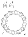
- a full ring vane nozzle 30 includes an outer diameter vane ring 32 and an inner diameter vane ring 34 defined about the engine axis X such that the outer diameter vane ring 32 and the inner diameter vane ring 34 are radially separated.
- the outer diameter vane ring 32 may form a portion of an outer core engine structure and the inner diameter vane ring 34 may form a portion of an inner core engine structure to at least partially define an annular gas flow path.
- the full ring vane nozzle 30 includes a multiple of circumferentially spaced apart turbine vanes 38, 40 which extend radially between the vane rings 32, 34.
- the full ring vane nozzle 30 includes a multiple of fixed turbine vanes 38 ( Figure 3 ) and a multiple of rotational turbine vanes 40 ( Figure 4 ) to provide a rigid structural assembly which accommodates thermal and aerodynamic loads during operation.
- the full, annular ring of the full ring vane nozzle 30 (also shown in Figure 5 ) provides a vane portion of one stage in the turbine section 18.
- the full ring vane nozzle 30 may be cast in one 360 degree piece with the outer diameter vane ring 32 and the inner diameter vane ring 34 having the fixed turbine vanes 38 cast therebetween with every other airfoil location - where the rotational turbine vanes 40 will be located.
- each one of the multiple of fixed turbine vanes 38 alternates with each one of the multiple of rotational turbine vanes 40. It should be understood, however, that any number of the multiple of fixed turbine vanes 38 may be interspersed with the rotational turbine vanes 40. That is, other non-limiting embodiments may include two or more fixed turbine vanes 38 interspersed between each rotational turbine vane 40.
- Each turbine vane 38, 40 includes a respective airfoil portion 42F, 42R defined by an outer airfoil wall surface 44F 44R between the leading edge 46F, 46R and a trailing edge 48F, 48R.
- Each turbine vane 38, 40 may include a fillet 52 to provide a transition between the airfoil portion 42F, 42R and the vane rings 32, 34.
- the outer airfoil wall surface 44F, 44R is typically shaped for use in a HPT, IT, or LPT of the turbine section 18.
- the outer airfoil wall surface 44F, 44R typically have a generally concave shaped portion forming a pressure side 44FP, 44RP and a generally convex shaped portion forming a suction side 44FS, 44RS. It should be understood that respective airfoil portion 42F, 42R defined by the outer airfoil wall surface 44F 44R may be generally equivalent or separately tailored to optimize flow characteristics and transient thermal expansion issues.
- An actuator system 54 includes an actuator such as an outer diameter unison ring (illustrated schematically at 56) which rotates an actuator ann 58 and thereby a spindle 60 of each rotational turbine vane 40.
- the spindle 60 rotates each rotational turbine vane 40 about a vane axis of rotation 62 relative the adjacent fixed turbine vanes 38 to selectively vary the turbine nozzle throat area. That is, movement of the rotational turbine vanes 40 relative the adjacent fixed turbine vanes 38 effectuates a change in throat area of the full ring vane nozzle 30.
- the spindle 60 may additionally facilitate cooling airflow into each rotational turbine vane 40 through, in on non-limiting embodiment, a hollow spindle 60. It should be understood that various cooling arrangements may alternatively or additionally be provided.
- the fixed turbine vane 38 provides a structural tie between the vane rings 32, 34 without internal seals or moving parts. Since the fixed turbine vane 38 and vane rings 32, 34 provide a rigid structure, the rotational turbine vane 40 may include a relatively less complicated rotation, support and sealing structure to provide the variable nozzle throat area capability which minimizes turbine pressure loss, leakage, expense and weight.
- the ring structure of the full ring vane nozzle 30 also readily transmits load between the inner structure and the outer structure of the engine 10 without transmitting loads through the rotational components.
- the vane axis of rotation 62 may be located approximately midway between the trailing edges of an adjacent fixed turbine vane 38 and rotational turbine vane 40 to selectively close the throat area between the rotational turbine vane 40 and the adjacent fixed turbine vanes 38 on either side of the rotational turbine vane 40. It should be understood that various rotational and positional schemes may benefit herefrom. Airfoils are conventionally rotated around the geometric center of gravity (CG) of the airfoil cross section.
- the rotational turbine vane 40 vane axis of rotation 62 may be biased toward the trailing edge 48R of the rotational turbine vane 40.
- a distance L is defined between the trailing edges of an adjacent fixed turbine vane 38 and rotational turbine vane 40.
- the rotational turbine vane 40 axis of rotation 62 is then positioned at L/2 from each adjacent fixed turbine vane 38 such that the axis of rotation 62 is located axially aft of the conventional geometric CG.
- the outer diameter vane ring 32 and the inner diameter vane ring 34 include a respective aperture 32A, 34A to receive a rotationally support assembly 66, 68 for the rotational turbine vane 40.
- the inner diameter rotationally support assembly 68 includes a bearing cartridge 70 and the outer diameter rotationally support assembly 66 includes a bearing assembly 72 and a fastener 74 which are received onto a spindle section 60A.
- each rotational turbine vane 40 is rotated and angled such that the spindle section 60A is received into the aperture 32A.
- the aperture 32A may be of a relatively enlarged diameter as compared to conventional arrangements to accommodate the angled insertion arrangement with the bearing assembly 72 sized to close the aperture 32A. That is, the bearing assembly 72 is enlarged and may include seal features to close aperture 32A.
- the fastener 74 is received on the spindle section 60A and may include the actuator arm 58 ( Figure 6 ) or other features.
- the bearing cartridge 70 is received through the aperture 34A and into a pocket 40A formed in the rotational turbine vane 40 to rotationally retain the rotational turbine vane 40 between the outer diameter vane ring 32 and the inner diameter vane ring 34. It should be understood that various mount, support, seal, and actuator arrangements may alternately or additionally be provided.
- rotation of the rotational turbine vanes 40 between a nominal position and a rotated position selectively changes the turbine nozzle throat area as each rotational turbine vane 40 concurrently changes the throat area between itself and the adjacent fixed turbine vanes 38. Since only half the vanes are rotated, the complexity and load requirements of the actuator system 54 are reduced. It should be understood that the angle of rotation may be larger for each rotational turbine vane 40, however, the air exit angle may be different for each side of the rotational turbine vane 40. Through CFD, however, this difference is known and may be utilized to provide an airfoil shape that addresses this differential flow behavior.
- the alternating rotational-fixed vane arrangement also facilitates a relatively less complicated rotation, support and sealing structure to provide the variable nozzle throat area capability to minimize turbine pressure loss, leakage, expense and weight.
- the present disclosure reduces moving parts and endwall losses typical of other systems yet provides an effective structural tie between the outer to inner flowpath. Since the entire rotational turbine vane 40 rotates - rather than a section thereof - there are no discontinuities in the airfoil surface to penalize efficiency and require cooling purge flow. Furthermore, the integrity of the airfoils is not dependent on the wear of relatively small moving parts and seals inside the vanes. Extensive steady and unsteady CFD studies have shown the aerodynamic risks of the alternating vane system are low, and the resultant aero-elastic environment is predictable with existing tools. The alternating vane geometry also provides the unique possibility of influencing the aero-elastic driver amplitude for the primary vane count frequency and half vane count frequency as a function of vane actuation.
Landscapes
- Engineering & Computer Science (AREA)
- Mechanical Engineering (AREA)
- General Engineering & Computer Science (AREA)
- Control Of Turbines (AREA)
- Turbine Rotor Nozzle Sealing (AREA)
- Supercharger (AREA)
Applications Claiming Priority (1)
| Application Number | Priority Date | Filing Date | Title |
|---|---|---|---|
| US12/778,084 US8007229B2 (en) | 2007-05-24 | 2010-05-11 | Variable area turbine vane arrangement |
Publications (3)
| Publication Number | Publication Date |
|---|---|
| EP2386723A2 true EP2386723A2 (de) | 2011-11-16 |
| EP2386723A3 EP2386723A3 (de) | 2012-01-18 |
| EP2386723B1 EP2386723B1 (de) | 2018-04-11 |
Family
ID=44147619
Family Applications (1)
| Application Number | Title | Priority Date | Filing Date |
|---|---|---|---|
| EP11165448.9A Active EP2386723B1 (de) | 2010-05-11 | 2011-05-10 | Verstellbare Turbinenleitschaufelanordnung |
Country Status (2)
| Country | Link |
|---|---|
| US (1) | US8007229B2 (de) |
| EP (1) | EP2386723B1 (de) |
Cited By (1)
| Publication number | Priority date | Publication date | Assignee | Title |
|---|---|---|---|---|
| WO2013165512A3 (en) * | 2012-02-28 | 2013-12-19 | United Technologies Corporation | Variable area turbine |
Families Citing this family (42)
| Publication number | Priority date | Publication date | Assignee | Title |
|---|---|---|---|---|
| US8943796B2 (en) | 2011-06-28 | 2015-02-03 | United Technologies Corporation | Variable cycle turbine engine |
| US9279335B2 (en) | 2011-08-03 | 2016-03-08 | United Technologies Corporation | Vane assembly for a gas turbine engine |
| US9273565B2 (en) | 2012-02-22 | 2016-03-01 | United Technologies Corporation | Vane assembly for a gas turbine engine |
| US9273566B2 (en) | 2012-06-22 | 2016-03-01 | United Technologies Corporation | Turbine engine variable area vane |
| US9103222B2 (en) | 2012-06-22 | 2015-08-11 | United Technologies Corporation | Turbine engine variable area vane with feather seal |
| US10215048B2 (en) | 2013-01-21 | 2019-02-26 | United Technologies Corporation | Variable area vane arrangement for a turbine engine |
| EP2948642B1 (de) | 2013-01-28 | 2020-10-21 | United Technologies Corporation | Mehrsegmentale verstellbare statorschaufel für schaufelanordnung mit einem variablen bereich |
| US9932988B2 (en) | 2013-02-15 | 2018-04-03 | United Technologies Corporation | Bushing arranged between a body and a shaft, and connected to the shaft |
| US10036264B2 (en) | 2013-06-14 | 2018-07-31 | United Technologies Corporation | Variable area gas turbine engine component having movable spar and shell |
| US9500122B2 (en) | 2013-06-28 | 2016-11-22 | General Electric Company | Variable geometry nozzle and associated method of operation |
| EP3907374B1 (de) | 2013-08-21 | 2025-05-28 | RTX Corporation | Turbinenanordnung mit variabler fläche und sekundärströmungsmodulation |
| EP3904641B1 (de) * | 2013-09-16 | 2023-09-06 | Raytheon Technologies Corporation | Verstellbare leitschaufelreihenanordnung einer turbine |
| EP3060763B1 (de) * | 2013-10-21 | 2020-04-15 | United Technologies Corporation | Vermeidung von strömung durch den spalt einer fehlertoleranten turbinenschaufel |
| EP3063374B1 (de) | 2013-10-31 | 2023-07-19 | Raytheon Technologies Corporation | Gasturbinentriebwerk und verfahren zum betreiben eines gasturbinentriebwerks |
| EP3090146B8 (de) * | 2013-11-25 | 2021-04-07 | Raytheon Technologies Corporation | Verfahren zur bereitstellung von kühlflüssigkeit an eine bewegliche schaufel |
| EP2980361B1 (de) | 2014-07-28 | 2018-02-14 | United Technologies Corporation | Kühlsystem einer statoranordnung für einen gasturbinenmotor mit variablem kühlflussmechanismus und verfahren zum betrieb |
| US9333603B1 (en) * | 2015-01-28 | 2016-05-10 | United Technologies Corporation | Method of assembling gas turbine engine section |
| US10018075B2 (en) * | 2015-04-22 | 2018-07-10 | General Electric Company | Methods for positioning neighboring nozzles of a gas turbine engine |
| US20170342854A1 (en) * | 2015-11-19 | 2017-11-30 | Barry J. Brown | Twin spool industrial gas turbine engine with variable inlet guide vanes |
| WO2017189566A2 (en) * | 2016-04-25 | 2017-11-02 | Florida Turbine Technologies, Inc. | Twin spool industrial gas turbine engine with variable inlet guide vanes |
| JP6631688B2 (ja) * | 2016-02-19 | 2020-01-15 | 株式会社Ihi | ノズル駆動機構、過給機、および、可変容量型過給機 |
| US10253648B2 (en) | 2016-03-04 | 2019-04-09 | General Electric Company | Modulated hybrid variable area turbine nozzle for gas turbine engine |
| US10458271B2 (en) | 2016-03-24 | 2019-10-29 | United Technologies Corporation | Cable drive system for variable vane operation |
| US10294813B2 (en) | 2016-03-24 | 2019-05-21 | United Technologies Corporation | Geared unison ring for variable vane actuation |
| US10415596B2 (en) | 2016-03-24 | 2019-09-17 | United Technologies Corporation | Electric actuation for variable vanes |
| US10443430B2 (en) | 2016-03-24 | 2019-10-15 | United Technologies Corporation | Variable vane actuation with rotating ring and sliding links |
| US10443431B2 (en) | 2016-03-24 | 2019-10-15 | United Technologies Corporation | Idler gear connection for multi-stage variable vane actuation |
| US10107130B2 (en) | 2016-03-24 | 2018-10-23 | United Technologies Corporation | Concentric shafts for remote independent variable vane actuation |
| US10329946B2 (en) | 2016-03-24 | 2019-06-25 | United Technologies Corporation | Sliding gear actuation for variable vanes |
| US10288087B2 (en) | 2016-03-24 | 2019-05-14 | United Technologies Corporation | Off-axis electric actuation for variable vanes |
| US10301962B2 (en) | 2016-03-24 | 2019-05-28 | United Technologies Corporation | Harmonic drive for shaft driving multiple stages of vanes via gears |
| US10190599B2 (en) | 2016-03-24 | 2019-01-29 | United Technologies Corporation | Drive shaft for remote variable vane actuation |
| US10329947B2 (en) | 2016-03-24 | 2019-06-25 | United Technologies Corporation | 35Geared unison ring for multi-stage variable vane actuation |
| GB201614803D0 (en) * | 2016-09-01 | 2016-10-19 | Rolls Royce Plc | Variable stator vane rigging |
| FR3062876B1 (fr) * | 2017-02-14 | 2021-03-12 | Safran Aircraft Engines | Compresseur haute pression pour turbomachine |
| US10711640B2 (en) | 2017-04-11 | 2020-07-14 | Raytheon Technologies Corporation | Cooled cooling air to blade outer air seal passing through a static vane |
| US10883376B2 (en) | 2019-02-01 | 2021-01-05 | Rolls-Royce Plc | Turbine vane assembly with ceramic matrix composite vanes |
| US11512667B2 (en) | 2019-02-25 | 2022-11-29 | Rolls-Royce North American Technologies Inc. | Anti-unstart for combined cycle high mach vehicles |
| US11480111B2 (en) * | 2019-05-15 | 2022-10-25 | Honeywell International Inc. | Variable area turbine nozzle and method |
| US11591915B2 (en) * | 2019-09-30 | 2023-02-28 | Raytheon Technologies Corporation | Multi-flow cooling circuit for gas turbine engine flowpath component |
| US11867069B2 (en) * | 2021-06-28 | 2024-01-09 | Rtx Corporation | Hybrid electric variable area turbine |
| US11773735B2 (en) | 2021-12-22 | 2023-10-03 | Rolls-Royce Plc | Vane ring assembly with ceramic matrix composite airfoils |
Family Cites Families (18)
| Publication number | Priority date | Publication date | Assignee | Title |
|---|---|---|---|---|
| US2819732A (en) * | 1954-07-14 | 1958-01-14 | Thompson Prod Inc | Variable area turbine entrance nozzle |
| US2994509A (en) * | 1959-04-10 | 1961-08-01 | Curtiss Wright Corp | Variable area turbine nozzle |
| US3966352A (en) * | 1975-06-30 | 1976-06-29 | United Technologies Corporation | Variable area turbine |
| FR2583820B1 (fr) * | 1985-06-20 | 1989-04-28 | Snecma | Dispositif de variation de section de passage d'un distributeur de turbine |
| US4990056A (en) * | 1989-11-16 | 1991-02-05 | General Motors Corporation | Stator vane stage in axial flow compressor |
| JP2865834B2 (ja) * | 1990-09-05 | 1999-03-08 | 株式会社日立製作所 | 遠心圧縮機 |
| US5690469A (en) * | 1996-06-06 | 1997-11-25 | United Technologies Corporation | Method and apparatus for replacing a vane assembly in a turbine engine |
| US5931636A (en) * | 1997-08-28 | 1999-08-03 | General Electric Company | Variable area turbine nozzle |
| US6536216B2 (en) | 2000-12-08 | 2003-03-25 | General Electric Company | Apparatus for injecting fuel into gas turbine engines |
| US6419464B1 (en) | 2001-01-16 | 2002-07-16 | Honeywell International Inc. | Vane for variable nozzle turbocharger |
| US6681558B2 (en) | 2001-03-26 | 2004-01-27 | General Electric Company | Method of increasing engine temperature limit margins |
| US6629817B2 (en) | 2001-07-05 | 2003-10-07 | General Electric Company | System and method for airfoil film cooling |
| CA2389484A1 (en) | 2002-06-06 | 2003-12-06 | Pratt & Whitney Canada Inc. | Optical measuremnet of vane ring throat area |
| GB2400416B (en) * | 2003-04-12 | 2006-08-16 | Rolls Royce Plc | Improvements in or relating to control of variable stator vanes in a gas turbine engine |
| FR2858027B1 (fr) * | 2003-07-21 | 2005-09-23 | Snecma Moteurs | Compresseur haute pression a cycle hybride et turbomachine comprenant un tel compresseur |
| US7134271B2 (en) | 2004-11-05 | 2006-11-14 | General Electric Company | Thrust vectoring aft FLADE engine |
| US7690889B2 (en) * | 2005-07-20 | 2010-04-06 | United Technologies Corporation | Inner diameter variable vane actuation mechanism |
| US20090067978A1 (en) * | 2007-05-24 | 2009-03-12 | Suljak Jr George T | Variable area turbine vane arrangement |
-
2010
- 2010-05-11 US US12/778,084 patent/US8007229B2/en active Active
-
2011
- 2011-05-10 EP EP11165448.9A patent/EP2386723B1/de active Active
Non-Patent Citations (1)
| Title |
|---|
| None |
Cited By (2)
| Publication number | Priority date | Publication date | Assignee | Title |
|---|---|---|---|---|
| WO2013165512A3 (en) * | 2012-02-28 | 2013-12-19 | United Technologies Corporation | Variable area turbine |
| US9957832B2 (en) | 2012-02-28 | 2018-05-01 | United Technologies Corporation | Variable area turbine |
Also Published As
| Publication number | Publication date |
|---|---|
| EP2386723B1 (de) | 2018-04-11 |
| US20100247293A1 (en) | 2010-09-30 |
| US8007229B2 (en) | 2011-08-30 |
| EP2386723A3 (de) | 2012-01-18 |
Similar Documents
| Publication | Publication Date | Title |
|---|---|---|
| EP2386723B1 (de) | Verstellbare Turbinenleitschaufelanordnung | |
| EP2071135B1 (de) | Dreidimensional konturierte Leitschaufelendwand für eine einstellbare Turbinenleitschaufelanordnung | |
| EP2995777B1 (de) | Leitschaufelring für einen gasturbinenmotor | |
| US10344601B2 (en) | Contoured flowpath surface | |
| EP2369138B1 (de) | Gasturbinenmotor mit nicht-axialsymmetrischer, oberflächenkonturierter Schaufelplattform | |
| US10287902B2 (en) | Variable stator vane undercut button | |
| EP3032033B2 (de) | Schaufelanordnung eines gasturbinenmotors | |
| US20090067978A1 (en) | Variable area turbine vane arrangement | |
| EP2169182A2 (de) | Integrierte Leitschaufelanordnung | |
| EP2817490B1 (de) | Schaufelanordnung für einen gasturbinenmotor | |
| EP2372102A2 (de) | Laufschaufelplattform einer Gasturbine | |
| EP3084139B1 (de) | Integral beschaufelter rotor eines gasturbinenmotor mit asymmetrischen grabenfillets | |
| US20150030443A1 (en) | Split damped outer shroud for gas turbine engine stator arrays | |
| EP3064711A1 (de) | Bauteil, zugehöriges gasturbinentriebwerk und verfahren | |
| US20230250723A1 (en) | Airfoil assembly with a differentially oriented stage | |
| EP3690189B1 (de) | Konturierte endwand für ein gasturbinentriebwerk | |
| EP3118414B1 (de) | Gasturbinentriebwerksschaufel | |
| EP3486496B1 (de) | Fan mit zwischendeckband für zweistromturbostrahltriebwerke | |
| EP3190266B1 (de) | Gasturbine mit rotornabendichtung | |
| EP2458154B1 (de) | Rotorscheibe mit asymmetrischer Nut für eine Laufschaufel, zugehörige Rotorscheibenanordnung und Herstellungsverfahren | |
| EP3461993B1 (de) | Gasturbinenlaufschaufel | |
| EP3428408B1 (de) | Einsatzelement am ende einer verstellbaren schaufel in einem gasturbinentriebwerk | |
| EP3034805B1 (de) | Dichtstreifen mit einem konischen radialabschnitt und abschnitt eines gasturbinenmotors mit einem solchen dichtstreifen | |
| EP3848558A1 (de) | Konturierter anschlag für leitschaufeln einer turbine mit variablem durchlass | |
| EP3623587B1 (de) | Schaufelprofilanordnug für ein gasturbinentriebwerk |
Legal Events
| Date | Code | Title | Description |
|---|---|---|---|
| AK | Designated contracting states |
Kind code of ref document: A2 Designated state(s): AL AT BE BG CH CY CZ DE DK EE ES FI FR GB GR HR HU IE IS IT LI LT LU LV MC MK MT NL NO PL PT RO RS SE SI SK SM TR |
|
| AX | Request for extension of the european patent |
Extension state: BA ME |
|
| PUAI | Public reference made under article 153(3) epc to a published international application that has entered the european phase |
Free format text: ORIGINAL CODE: 0009012 |
|
| PUAL | Search report despatched |
Free format text: ORIGINAL CODE: 0009013 |
|
| AK | Designated contracting states |
Kind code of ref document: A3 Designated state(s): AL AT BE BG CH CY CZ DE DK EE ES FI FR GB GR HR HU IE IS IT LI LT LU LV MC MK MT NL NO PL PT RO RS SE SI SK SM TR |
|
| AX | Request for extension of the european patent |
Extension state: BA ME |
|
| RIC1 | Information provided on ipc code assigned before grant |
Ipc: F01D 17/16 20060101ALI20111215BHEP Ipc: F01D 9/04 20060101AFI20111215BHEP |
|
| 17P | Request for examination filed |
Effective date: 20120718 |
|
| 17Q | First examination report despatched |
Effective date: 20151026 |
|
| RAP1 | Party data changed (applicant data changed or rights of an application transferred) |
Owner name: UNITED TECHNOLOGIES CORPORATION |
|
| STAA | Information on the status of an ep patent application or granted ep patent |
Free format text: STATUS: EXAMINATION IS IN PROGRESS |
|
| REG | Reference to a national code |
Ref country code: DE Ref legal event code: R079 Ref document number: 602011047319 Country of ref document: DE Free format text: PREVIOUS MAIN CLASS: F01D0009040000 Ipc: F04D0029560000 |
|
| GRAP | Despatch of communication of intention to grant a patent |
Free format text: ORIGINAL CODE: EPIDOSNIGR1 |
|
| STAA | Information on the status of an ep patent application or granted ep patent |
Free format text: STATUS: GRANT OF PATENT IS INTENDED |
|
| RIC1 | Information provided on ipc code assigned before grant |
Ipc: F04D 29/56 20060101AFI20171003BHEP Ipc: F01D 17/16 20060101ALI20171003BHEP Ipc: F01D 9/04 20060101ALI20171003BHEP |
|
| INTG | Intention to grant announced |
Effective date: 20171026 |
|
| GRAS | Grant fee paid |
Free format text: ORIGINAL CODE: EPIDOSNIGR3 |
|
| GRAA | (expected) grant |
Free format text: ORIGINAL CODE: 0009210 |
|
| STAA | Information on the status of an ep patent application or granted ep patent |
Free format text: STATUS: THE PATENT HAS BEEN GRANTED |
|
| AK | Designated contracting states |
Kind code of ref document: B1 Designated state(s): AL AT BE BG CH CY CZ DE DK EE ES FI FR GB GR HR HU IE IS IT LI LT LU LV MC MK MT NL NO PL PT RO RS SE SI SK SM TR |
|
| REG | Reference to a national code |
Ref country code: GB Ref legal event code: FG4D |
|
| REG | Reference to a national code |
Ref country code: CH Ref legal event code: EP |
|
| REG | Reference to a national code |
Ref country code: AT Ref legal event code: REF Ref document number: 988340 Country of ref document: AT Kind code of ref document: T Effective date: 20180415 |
|
| REG | Reference to a national code |
Ref country code: IE Ref legal event code: FG4D |
|
| REG | Reference to a national code |
Ref country code: DE Ref legal event code: R096 Ref document number: 602011047319 Country of ref document: DE |
|
| REG | Reference to a national code |
Ref country code: NL Ref legal event code: MP Effective date: 20180411 |
|
| REG | Reference to a national code |
Ref country code: LT Ref legal event code: MG4D |
|
| PG25 | Lapsed in a contracting state [announced via postgrant information from national office to epo] |
Ref country code: NL Free format text: LAPSE BECAUSE OF FAILURE TO SUBMIT A TRANSLATION OF THE DESCRIPTION OR TO PAY THE FEE WITHIN THE PRESCRIBED TIME-LIMIT Effective date: 20180411 |
|
| PG25 | Lapsed in a contracting state [announced via postgrant information from national office to epo] |
Ref country code: BG Free format text: LAPSE BECAUSE OF FAILURE TO SUBMIT A TRANSLATION OF THE DESCRIPTION OR TO PAY THE FEE WITHIN THE PRESCRIBED TIME-LIMIT Effective date: 20180711 Ref country code: NO Free format text: LAPSE BECAUSE OF FAILURE TO SUBMIT A TRANSLATION OF THE DESCRIPTION OR TO PAY THE FEE WITHIN THE PRESCRIBED TIME-LIMIT Effective date: 20180711 Ref country code: FI Free format text: LAPSE BECAUSE OF FAILURE TO SUBMIT A TRANSLATION OF THE DESCRIPTION OR TO PAY THE FEE WITHIN THE PRESCRIBED TIME-LIMIT Effective date: 20180411 Ref country code: SE Free format text: LAPSE BECAUSE OF FAILURE TO SUBMIT A TRANSLATION OF THE DESCRIPTION OR TO PAY THE FEE WITHIN THE PRESCRIBED TIME-LIMIT Effective date: 20180411 Ref country code: ES Free format text: LAPSE BECAUSE OF FAILURE TO SUBMIT A TRANSLATION OF THE DESCRIPTION OR TO PAY THE FEE WITHIN THE PRESCRIBED TIME-LIMIT Effective date: 20180411 Ref country code: AL Free format text: LAPSE BECAUSE OF FAILURE TO SUBMIT A TRANSLATION OF THE DESCRIPTION OR TO PAY THE FEE WITHIN THE PRESCRIBED TIME-LIMIT Effective date: 20180411 Ref country code: LT Free format text: LAPSE BECAUSE OF FAILURE TO SUBMIT A TRANSLATION OF THE DESCRIPTION OR TO PAY THE FEE WITHIN THE PRESCRIBED TIME-LIMIT Effective date: 20180411 Ref country code: PL Free format text: LAPSE BECAUSE OF FAILURE TO SUBMIT A TRANSLATION OF THE DESCRIPTION OR TO PAY THE FEE WITHIN THE PRESCRIBED TIME-LIMIT Effective date: 20180411 |
|
| PG25 | Lapsed in a contracting state [announced via postgrant information from national office to epo] |
Ref country code: LV Free format text: LAPSE BECAUSE OF FAILURE TO SUBMIT A TRANSLATION OF THE DESCRIPTION OR TO PAY THE FEE WITHIN THE PRESCRIBED TIME-LIMIT Effective date: 20180411 Ref country code: RS Free format text: LAPSE BECAUSE OF FAILURE TO SUBMIT A TRANSLATION OF THE DESCRIPTION OR TO PAY THE FEE WITHIN THE PRESCRIBED TIME-LIMIT Effective date: 20180411 Ref country code: HR Free format text: LAPSE BECAUSE OF FAILURE TO SUBMIT A TRANSLATION OF THE DESCRIPTION OR TO PAY THE FEE WITHIN THE PRESCRIBED TIME-LIMIT Effective date: 20180411 Ref country code: GR Free format text: LAPSE BECAUSE OF FAILURE TO SUBMIT A TRANSLATION OF THE DESCRIPTION OR TO PAY THE FEE WITHIN THE PRESCRIBED TIME-LIMIT Effective date: 20180712 |
|
| REG | Reference to a national code |
Ref country code: CH Ref legal event code: PL |
|
| REG | Reference to a national code |
Ref country code: AT Ref legal event code: MK05 Ref document number: 988340 Country of ref document: AT Kind code of ref document: T Effective date: 20180411 |
|
| PG25 | Lapsed in a contracting state [announced via postgrant information from national office to epo] |
Ref country code: PT Free format text: LAPSE BECAUSE OF FAILURE TO SUBMIT A TRANSLATION OF THE DESCRIPTION OR TO PAY THE FEE WITHIN THE PRESCRIBED TIME-LIMIT Effective date: 20180813 |
|
| REG | Reference to a national code |
Ref country code: DE Ref legal event code: R097 Ref document number: 602011047319 Country of ref document: DE |
|
| REG | Reference to a national code |
Ref country code: BE Ref legal event code: MM Effective date: 20180531 |
|
| PG25 | Lapsed in a contracting state [announced via postgrant information from national office to epo] |
Ref country code: EE Free format text: LAPSE BECAUSE OF FAILURE TO SUBMIT A TRANSLATION OF THE DESCRIPTION OR TO PAY THE FEE WITHIN THE PRESCRIBED TIME-LIMIT Effective date: 20180411 Ref country code: AT Free format text: LAPSE BECAUSE OF FAILURE TO SUBMIT A TRANSLATION OF THE DESCRIPTION OR TO PAY THE FEE WITHIN THE PRESCRIBED TIME-LIMIT Effective date: 20180411 Ref country code: RO Free format text: LAPSE BECAUSE OF FAILURE TO SUBMIT A TRANSLATION OF THE DESCRIPTION OR TO PAY THE FEE WITHIN THE PRESCRIBED TIME-LIMIT Effective date: 20180411 Ref country code: CZ Free format text: LAPSE BECAUSE OF FAILURE TO SUBMIT A TRANSLATION OF THE DESCRIPTION OR TO PAY THE FEE WITHIN THE PRESCRIBED TIME-LIMIT Effective date: 20180411 Ref country code: MC Free format text: LAPSE BECAUSE OF FAILURE TO SUBMIT A TRANSLATION OF THE DESCRIPTION OR TO PAY THE FEE WITHIN THE PRESCRIBED TIME-LIMIT Effective date: 20180411 Ref country code: SK Free format text: LAPSE BECAUSE OF FAILURE TO SUBMIT A TRANSLATION OF THE DESCRIPTION OR TO PAY THE FEE WITHIN THE PRESCRIBED TIME-LIMIT Effective date: 20180411 Ref country code: DK Free format text: LAPSE BECAUSE OF FAILURE TO SUBMIT A TRANSLATION OF THE DESCRIPTION OR TO PAY THE FEE WITHIN THE PRESCRIBED TIME-LIMIT Effective date: 20180411 |
|
| PLBE | No opposition filed within time limit |
Free format text: ORIGINAL CODE: 0009261 |
|
| STAA | Information on the status of an ep patent application or granted ep patent |
Free format text: STATUS: NO OPPOSITION FILED WITHIN TIME LIMIT |
|
| REG | Reference to a national code |
Ref country code: IE Ref legal event code: MM4A |
|
| PG25 | Lapsed in a contracting state [announced via postgrant information from national office to epo] |
Ref country code: SM Free format text: LAPSE BECAUSE OF FAILURE TO SUBMIT A TRANSLATION OF THE DESCRIPTION OR TO PAY THE FEE WITHIN THE PRESCRIBED TIME-LIMIT Effective date: 20180411 Ref country code: IT Free format text: LAPSE BECAUSE OF FAILURE TO SUBMIT A TRANSLATION OF THE DESCRIPTION OR TO PAY THE FEE WITHIN THE PRESCRIBED TIME-LIMIT Effective date: 20180411 Ref country code: LI Free format text: LAPSE BECAUSE OF NON-PAYMENT OF DUE FEES Effective date: 20180531 Ref country code: CH Free format text: LAPSE BECAUSE OF NON-PAYMENT OF DUE FEES Effective date: 20180531 |
|
| 26N | No opposition filed |
Effective date: 20190114 |
|
| PG25 | Lapsed in a contracting state [announced via postgrant information from national office to epo] |
Ref country code: LU Free format text: LAPSE BECAUSE OF NON-PAYMENT OF DUE FEES Effective date: 20180510 |
|
| PG25 | Lapsed in a contracting state [announced via postgrant information from national office to epo] |
Ref country code: IE Free format text: LAPSE BECAUSE OF NON-PAYMENT OF DUE FEES Effective date: 20180510 Ref country code: FR Free format text: LAPSE BECAUSE OF NON-PAYMENT OF DUE FEES Effective date: 20180611 |
|
| PG25 | Lapsed in a contracting state [announced via postgrant information from national office to epo] |
Ref country code: SI Free format text: LAPSE BECAUSE OF FAILURE TO SUBMIT A TRANSLATION OF THE DESCRIPTION OR TO PAY THE FEE WITHIN THE PRESCRIBED TIME-LIMIT Effective date: 20180411 Ref country code: BE Free format text: LAPSE BECAUSE OF NON-PAYMENT OF DUE FEES Effective date: 20180531 |
|
| PG25 | Lapsed in a contracting state [announced via postgrant information from national office to epo] |
Ref country code: MT Free format text: LAPSE BECAUSE OF NON-PAYMENT OF DUE FEES Effective date: 20180510 |
|
| PG25 | Lapsed in a contracting state [announced via postgrant information from national office to epo] |
Ref country code: TR Free format text: LAPSE BECAUSE OF FAILURE TO SUBMIT A TRANSLATION OF THE DESCRIPTION OR TO PAY THE FEE WITHIN THE PRESCRIBED TIME-LIMIT Effective date: 20180411 |
|
| PG25 | Lapsed in a contracting state [announced via postgrant information from national office to epo] |
Ref country code: HU Free format text: LAPSE BECAUSE OF FAILURE TO SUBMIT A TRANSLATION OF THE DESCRIPTION OR TO PAY THE FEE WITHIN THE PRESCRIBED TIME-LIMIT; INVALID AB INITIO Effective date: 20110510 |
|
| PG25 | Lapsed in a contracting state [announced via postgrant information from national office to epo] |
Ref country code: MK Free format text: LAPSE BECAUSE OF NON-PAYMENT OF DUE FEES Effective date: 20180411 Ref country code: CY Free format text: LAPSE BECAUSE OF FAILURE TO SUBMIT A TRANSLATION OF THE DESCRIPTION OR TO PAY THE FEE WITHIN THE PRESCRIBED TIME-LIMIT Effective date: 20180411 |
|
| PG25 | Lapsed in a contracting state [announced via postgrant information from national office to epo] |
Ref country code: IS Free format text: LAPSE BECAUSE OF FAILURE TO SUBMIT A TRANSLATION OF THE DESCRIPTION OR TO PAY THE FEE WITHIN THE PRESCRIBED TIME-LIMIT Effective date: 20180811 |
|
| REG | Reference to a national code |
Ref country code: DE Ref legal event code: R081 Ref document number: 602011047319 Country of ref document: DE Owner name: RAYTHEON TECHNOLOGIES CORPORATION (N.D.GES.D.S, US Free format text: FORMER OWNER: UNITED TECHNOLOGIES CORPORATION, FARMINGTON, CONN., US Ref country code: DE Ref legal event code: R081 Ref document number: 602011047319 Country of ref document: DE Owner name: RTX CORPORATION (N.D.GES.D. STAATES DELAWARE),, US Free format text: FORMER OWNER: UNITED TECHNOLOGIES CORPORATION, FARMINGTON, CONN., US |
|
| P01 | Opt-out of the competence of the unified patent court (upc) registered |
Effective date: 20230519 |
|
| PGFP | Annual fee paid to national office [announced via postgrant information from national office to epo] |
Ref country code: DE Payment date: 20250423 Year of fee payment: 15 |
|
| PGFP | Annual fee paid to national office [announced via postgrant information from national office to epo] |
Ref country code: GB Payment date: 20250423 Year of fee payment: 15 |
|
| REG | Reference to a national code |
Ref country code: DE Ref legal event code: R081 Ref document number: 602011047319 Country of ref document: DE Owner name: RTX CORPORATION (N.D.GES.D. STAATES DELAWARE),, US Free format text: FORMER OWNER: RAYTHEON TECHNOLOGIES CORPORATION (N.D.GES.D.STAATES DELAWARE), ARLINGTON, VA, US |