EP2386771A2 - Ventouse dotée d'un indicateur de la force de retenue - Google Patents
Ventouse dotée d'un indicateur de la force de retenue Download PDFInfo
- Publication number
- EP2386771A2 EP2386771A2 EP11003975A EP11003975A EP2386771A2 EP 2386771 A2 EP2386771 A2 EP 2386771A2 EP 11003975 A EP11003975 A EP 11003975A EP 11003975 A EP11003975 A EP 11003975A EP 2386771 A2 EP2386771 A2 EP 2386771A2
- Authority
- EP
- European Patent Office
- Prior art keywords
- suction
- suction cup
- resilient element
- display
- housing
- Prior art date
- Legal status (The legal status is an assumption and is not a legal conclusion. Google has not performed a legal analysis and makes no representation as to the accuracy of the status listed.)
- Granted
Links
Images

Classifications
-
- F—MECHANICAL ENGINEERING; LIGHTING; HEATING; WEAPONS; BLASTING
- F16—ENGINEERING ELEMENTS AND UNITS; GENERAL MEASURES FOR PRODUCING AND MAINTAINING EFFECTIVE FUNCTIONING OF MACHINES OR INSTALLATIONS; THERMAL INSULATION IN GENERAL
- F16B—DEVICES FOR FASTENING OR SECURING CONSTRUCTIONAL ELEMENTS OR MACHINE PARTS TOGETHER, e.g. NAILS, BOLTS, CIRCLIPS, CLAMPS, CLIPS OR WEDGES; JOINTS OR JOINTING
- F16B47/00—Suction cups for attaching purposes; Equivalent means using adhesives
- F16B47/006—Suction cups for attaching purposes; Equivalent means using adhesives the suction cups being activated by the rotation of a cranked lever arm
Definitions
- the invention relates to a device for attachment to a surface with a suction cup.
- Suction cups that are equipped with the widespread tensioning mechanisms, such as eccentrics, curves or other lever mechanisms that exert traction on the suction plate, have as well as the systems with springs of different construction, such. B. additional plastic cages or other resilient elements, the disadvantage that only the greatest possible mechanical tensile force is exerted on the suction cup. This leads to common problems in everyday operation, since the suction elements dissolve even with small changes in the ambient conditions. So the common suction cup holder solve, for example, in frost or high heat.
- a suction cup dissolves faster in changing environmental conditions when the vacuum is too high. In shock occurring peak loads, such. As in an accident, the negative pressure breaks through the lack of elasticity in the suction cup immediately together and the holder dissolves and is when used in vehicles to a dangerous projectile.
- suction cups Due to the technical possibility of producing the suction cups today from a variety of materials, it is technically possible to use suction cups to produce with extremely soft edge zones.
- These suction plates can also be attached to structured counter work surfaces such as dashboards. On these surfaces, the suction pressure can be adjusted by a suitably designed compression spring, but there is always a pressure drop over a few days or weeks.
- the devices mounted in these places are used in the extended function, z. B. as a speakerphone. The driver then uses these devices as an input terminal, resulting in additional load on the suction connection.
- the previously known systems are usually not adjustable in the holding force or can only be set during production to a certain suction strength. An adaptation to the different surfaces or to different environmental conditions is no longer possible after production.
- Object of the present invention is therefore to improve existing fastening devices with suction cups.
- this object solves a device for attachment to a surface with a suction cup, the device having a measuring device for measuring the suction force. This has the advantage that a decrease in the suction force can be detected early.
- the measuring device acts mechanically.
- the position of the suction cup in comparison to other stationary components can be determined by markings.
- the measuring device may be electronic. This can happen, for example, through a system of coils or other electronic elements.
- the position of moving and stationary parts of the fastening device z. B. measured a change in the electric field.
- the device has a display for displaying the suction force
- the values determined by the measuring device can be output. For example, the working position of the suction cup and thus the suction force can be displayed.
- This display can be mechanical-optical.
- position markings can give exact information about the working position of the suction cup.
- the different markings directly signal the working condition.
- warning marks which are only indications of a change, can be realized. Thus, for example, even during long car rides may well be a hint to see that requires no immediate action.
- the display can also be electronic. There are numerous output options.
- the device is equipped with an acoustic and / or an optical display, so that different perception channels of the user can be addressed.
- the receiver may, for example, also be the device used.
- the state of the safe function or the release of the holding force of the holder can be displayed in the display of the device used.
- the measured suction force values can be converted into an infinitely variable display by an electronic evaluation unit in the case of electronic position detection and thus displayed, for example, in percent or in an optical green red bar. Even changing, acoustic signals can be generated.
- the device has a power supply or can be connected to a power supply. If the device has a housing, then a battery or a rechargeable battery can be accommodated therein, which provides the necessary electrical energy.
- the system is equipped with a solar module.
- This may for example be part of the housing. Also a connection with an external power source is possible.
- the power source may also be the device used in the holder.
- the device has a housing and the housing is smaller than the suction cup.
- the suction cup protrudes significantly beyond the housing.
- the housing presses on the edge of the suction plate and thereby leads to a better attachment.
- this has a tab. By pulling on this tab, the suction cup can be removed from the surface to which it is attached.
- the device may comprise an actuating device, in particular an actuating button for increasing the suction force.
- an actuating button for increasing the suction force.
- a one-to-one-touch function provided by the operating button may be provided by the operator, such as a car driver, in any appropriate situation, such as a car driver. B. be performed at a stop at a red light.
- a pressure on the operating button leads to a restoration of the system for both the measuring device as well as for the display and the actuator.
- a pressure before starting the journey is as easy as the necessary Look in the rearview mirror. This function contributes significantly to the secure attachment, without the entire system needs to be adjusted.
- the fastening device has a resilient element. This can be used for all of the three functions - the measuring device, the display device and the actuating device.
- the resilient element may be a helical spring.
- the proportion of the spring that is effective can be adjusted. As a result, the spring strength and thus the suction strength and thus the holding force can be adjusted.
- the resilient element may also be exchangeable. Also, an individual adaptation to the application is possible and a use in a variety of applications imaginable.
- the holding force can thus be set at a later time and not only during production to a certain suction strength.
- the resilient element is a conical spring. This has the advantage that when the resilient element is compressed, the turns of the spring can be pressed together. This allows the spring to be compressed completely flat.
- the safety suction cup holder according to the invention is thus based on an interaction of a spring function, in conjunction with a directly flanged on the suction cup actuator button.
- the operating button precisely measures the position control of the suction plate and registers even the smallest changes. Decisive for the precision of the bearing control of the suction cup is the decoupling of the suction cup and the limiting device in which the actuating knob is guided.
- the actuating knob thus also serves as a measuring device.
- microswitch If the operating knob is mounted in an exact guide of the housing for the suction cup, it is possible by microswitch to query the position of the actuating knob. For this purpose, for example, in the operating knob differently deep rings or recesses or elevations may be introduced. Due to the appropriate positioning of the microswitch now the respective critical or non-critical working position of the suction cup is to be transmitted to electronic or electrical elements. These can then trigger an optical and / or acoustic signal.
- Another way to query the position of the actuator button is that a coil is placed in both the actuator knob and in the sleeve holding it and the displacement of these coils is measured to each other.
- the device has a biasing lever which fixes the actuating device against the force of the resilient element.
- the biasing lever holds the actuator completely in the sleeve in which it is stored. The actuator button is then not over this out.
- this position of the actuating button corresponds exactly to the rest position of the suction cup. Its membrane is in a fully extended state. When the preload lever is removed, the force of the resilient member acts to pull the sucker away from the pad in the middle. This creates the maximum possible negative pressure.
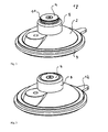
- the holding device 1 with a housing 2 and a suction cup 3 is in working position. This can be seen because the operating knob 4 is pressed down in a sleeve 5 attached to the housing 2.
- the fastening button 4 When the fastening button 4 is pressed down, the air escapes under the suction cup 3.
- the rubber material of the suction cup 3 seals it against a work surface (not shown).
- the compression spring 6 presses the operation knob 4, which is connected by means of a connecting piece 7 and the screw 8 with the suction cup 3, upwards and the vacuum is formed.
- the operating knob 4 is held via the connection 7 as shown by the vacuum on the suction cup 3 in the sleeve 5.
- the housing 2 also has a fastening device 9 with a bore 10, on which, for example, a holder for a small appliance can be attached.
- the fastening device 1 with suction cup 3 and housing 2 in FIG. 2 is, however, at rest.
- the operating knob 4 in the sleeve 5 by the compression spring (not visible) is pressed permanently upwards.
- a colored mark 11 is visible. This also serves to display the suction during operation of the holding device l. If the vacuum escapes over time from the working position, the colored marking or even several colored markings become visible. It can thus be visualized that the suction power is still sufficient or possibly no longer sufficient.
- the holding device 1 in FIG. 3 is again in working position.
- the actuating button is pressed in the sleeve 5 down.
- the colored marking is no longer visible.
- the suction cup 3 forms the largest possible vacuum with the work surface.
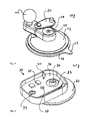
- the holding device 11 with a housing 12 and a suction cup 13 is also in working position. This can also be seen here, since the actuating button 14 is pressed down in a sleeve 15 attached to the housing 12.
- fastening devices has the in FIG. 4 dargixie fastening device 11 a biasing lever 21. This can be pushed over the fastening knob 14, whereby it is pressed down. The membrane of the suction cup 13 is then in a relaxed position, so that it rests completely when placed on a surface. If the biasing lever 20 is pushed to the side, presses the compression spring 16, which is designed as a conical spring, the operating knob 14 upwards. This is connected by means of a connecting piece 17 and the screw 18 with the suction cup 13. So the suction cup 13 is pulled up and the vacuum is created. If the suction cup 13 to be removed from the surface again so this is possible by pulling on the tab 21.
- the fastening device 11 has a ball head 19, to which, for example, a small appliance provided with a corresponding counterpart can be plugged.
- FIG. 5 a part of a holding device 31 is shown. This consists of the housing 32 and the measuring and display device 33. The suction cup itself is not shown.
- the actuating button 34 is located in the sleeve 35.
- the position of the two elements relative to each other is measured by coils which are arranged in the two elements.
- the result of this measurement is evaluated by the electronics 37 located on the circuit board 36. In this case, the values of the reference coils 38, 39 are used for the evaluation.
- the result of this evaluation is output via the light-emitting diode 40.
- the total path of the control knob in the sleeve can be about 2 mm to 2.5 mm.
- the diode would then display green for a range of 0 mm to 0.6 mm, glow amber between 0.6 mm and 1.1 mm, and then emit red light to alert the operator that secure attachment is no longer guaranteed is.
Landscapes
- Engineering & Computer Science (AREA)
- General Engineering & Computer Science (AREA)
- Mechanical Engineering (AREA)
- Hooks, Suction Cups, And Attachment By Adhesive Means (AREA)
- Details Of Spanners, Wrenches, And Screw Drivers And Accessories (AREA)
Applications Claiming Priority (2)
| Application Number | Priority Date | Filing Date | Title |
|---|---|---|---|
| DE102010020477 | 2010-05-14 | ||
| DE201010025738 DE102010025738A1 (de) | 2010-05-14 | 2010-07-01 | Saugnapf mit Haltekraftanzeige |
Publications (3)
| Publication Number | Publication Date |
|---|---|
| EP2386771A2 true EP2386771A2 (fr) | 2011-11-16 |
| EP2386771A3 EP2386771A3 (fr) | 2012-01-25 |
| EP2386771B1 EP2386771B1 (fr) | 2015-08-26 |
Family
ID=44542928
Family Applications (1)
| Application Number | Title | Priority Date | Filing Date |
|---|---|---|---|
| EP11003975.7A Active EP2386771B1 (fr) | 2010-05-14 | 2011-05-13 | Ventouse dotée d'un indicateur de la force de retenue |
Country Status (2)
| Country | Link |
|---|---|
| EP (1) | EP2386771B1 (fr) |
| DE (1) | DE102010025738A1 (fr) |
Cited By (6)
| Publication number | Priority date | Publication date | Assignee | Title |
|---|---|---|---|---|
| CN103470611A (zh) * | 2013-09-06 | 2013-12-25 | 中山市太力家庭用品制造有限公司 | 一种吸盘罩及吸盘 |
| CN103470612A (zh) * | 2013-03-08 | 2013-12-25 | 中山市太力家庭用品制造有限公司 | 一种具有密封件的吸盘 |
| CN103470610A (zh) * | 2013-09-06 | 2013-12-25 | 中山市太力家庭用品制造有限公司 | 一种带凸筋的吸盘罩及吸盘 |
| WO2015106754A1 (fr) * | 2014-01-17 | 2015-07-23 | Tormaxx Gmbh | Système de fixation et ensemble équipé d'un tel système de fixation |
| CN107143570A (zh) * | 2017-06-27 | 2017-09-08 | 安徽中兴流体装备有限责任公司 | 一种结构改良的阀门吸盘 |
| CN107269672A (zh) * | 2017-06-27 | 2017-10-20 | 安徽中兴流体装备有限责任公司 | 一种多功能阀门吸盘 |
Families Citing this family (1)
| Publication number | Priority date | Publication date | Assignee | Title |
|---|---|---|---|---|
| DE102016012882A1 (de) | 2016-10-28 | 2017-06-01 | Daimler Ag | Messvorrichtung zur Ermittlung einer Haltekraft |
Family Cites Families (15)
| Publication number | Priority date | Publication date | Assignee | Title |
|---|---|---|---|---|
| GB1193899A (en) * | 1968-03-06 | 1970-06-03 | Giuseppe Calligaro | Improvements in or relating to Suction Grip Devices |
| AU2006209367B2 (en) * | 1999-05-13 | 2008-12-11 | Homayoon Kazerooni | Human power amplifier for lifting load including apparatus for preventing slack in lifting cable |
| US6437560B1 (en) * | 2000-10-31 | 2002-08-20 | Syron Engineering & Manufacturing, Llc | Combined suction cup and isolated sensor |
| US7645111B2 (en) * | 2002-11-05 | 2010-01-12 | Central Glass Company, Limited | System for putting glass plates to target positions |
| JP4000303B2 (ja) * | 2003-03-25 | 2007-10-31 | 富士フイルム株式会社 | シート体の吸着枚葉方法及び吸着枚葉装置 |
| DE202004003324U1 (de) * | 2004-01-24 | 2004-05-19 | Universitätsklinikum Lübeck | Roboterfuß mit Saugnäpfen zur Fortbewegung auf beliebig geneigten, glatten Flächen |
| JP2006064168A (ja) * | 2004-08-30 | 2006-03-09 | Golden Peak Plastic Works Ltd | 吸盤の装着構造 |
| DE102005051201B4 (de) * | 2005-09-22 | 2008-01-17 | J. Schmalz Gmbh | Sauggreifer |
| DE102005045681B4 (de) * | 2005-09-24 | 2007-07-26 | Eckelt Glas Gmbh | Verfahren zum Steuern von Unterdruck-Hebezeugen und Lastsicherungsvorrichtung für Unterdruck-Hebezeuge sowie deren Verwendung |
| DE102007002756A1 (de) * | 2006-02-17 | 2007-08-23 | Heidelberger Druckmaschinen Ag | Verfahren und Vorrichtung zum Separieren eines Bogens von einem Bogenstapel |
| US7628434B2 (en) * | 2006-07-12 | 2009-12-08 | Honda Motor Co., Ltd. | Vacuum-operated vehicle glass handling system |
| US7455269B1 (en) * | 2007-07-09 | 2008-11-25 | Li-Sheng Chien | Suction device |
| KR200449191Y1 (ko) * | 2007-11-21 | 2010-06-23 | 한진복 | 진공 흡착구 |
| DE102008015648A1 (de) * | 2008-03-25 | 2009-10-01 | Bohle Ag | Vakuumheber |
| DE202008013507U1 (de) * | 2008-10-10 | 2009-03-05 | Chien, Li Sheng | Saugnapfvorrichtung, welche in der Lage ist, eine Haftkraft zu erkennen |
-
2010
- 2010-07-01 DE DE201010025738 patent/DE102010025738A1/de not_active Ceased
-
2011
- 2011-05-13 EP EP11003975.7A patent/EP2386771B1/fr active Active
Non-Patent Citations (1)
| Title |
|---|
| None |
Cited By (8)
| Publication number | Priority date | Publication date | Assignee | Title |
|---|---|---|---|---|
| CN103470612A (zh) * | 2013-03-08 | 2013-12-25 | 中山市太力家庭用品制造有限公司 | 一种具有密封件的吸盘 |
| CN103470611A (zh) * | 2013-09-06 | 2013-12-25 | 中山市太力家庭用品制造有限公司 | 一种吸盘罩及吸盘 |
| CN103470610A (zh) * | 2013-09-06 | 2013-12-25 | 中山市太力家庭用品制造有限公司 | 一种带凸筋的吸盘罩及吸盘 |
| WO2015106754A1 (fr) * | 2014-01-17 | 2015-07-23 | Tormaxx Gmbh | Système de fixation et ensemble équipé d'un tel système de fixation |
| CN106461154A (zh) * | 2014-01-17 | 2017-02-22 | 托马克斯有限责任公司 | 保持系统以及带有这样的保持系统的套件 |
| US10072794B2 (en) | 2014-01-17 | 2018-09-11 | Tormaxx Gmbh | Mounting system and set comprising a mounting system of said type |
| CN107143570A (zh) * | 2017-06-27 | 2017-09-08 | 安徽中兴流体装备有限责任公司 | 一种结构改良的阀门吸盘 |
| CN107269672A (zh) * | 2017-06-27 | 2017-10-20 | 安徽中兴流体装备有限责任公司 | 一种多功能阀门吸盘 |
Also Published As
| Publication number | Publication date |
|---|---|
| EP2386771A3 (fr) | 2012-01-25 |
| DE102010025738A1 (de) | 2011-11-17 |
| EP2386771B1 (fr) | 2015-08-26 |
Similar Documents
| Publication | Publication Date | Title |
|---|---|---|
| EP2386771B1 (fr) | Ventouse dotée d'un indicateur de la force de retenue | |
| DE4310855A1 (de) | Einrichtung zur Überwachung wenigstens einer Verbindung eines medizinischen Schlauchleitungssystems | |
| CH713114A2 (de) | Elektronisches Zusatzmodul für Injektionsgeräte. | |
| DE10103952A1 (de) | Vorrichtung zur Energieversorgung eines Sensors | |
| EP1948006A2 (fr) | Capteur de pouls, pulsometre, oxymetre, levier de commande et casque | |
| DE102015014585A1 (de) | Sensorisch überwachter Blocksauger | |
| DE2928153A1 (de) | Bremsentestvorrichtung | |
| DE102004025123A1 (de) | Hörhilfegerät oder Hörgerätesystem mit akustischer Batterieanzeige | |
| EP2093134B1 (fr) | Dispositif de contrôle et d'affichage de la position de composants d'embrayages de véhicules | |
| DE102016221633A1 (de) | Reifenluftdrucküberwachungsvorrichtung | |
| EP3533076A1 (fr) | Dispositif commutateur pour machine-outil | |
| WO2018050264A1 (fr) | Dispositif de surveillance de l'état d'usure, module complémentaire pour un dispositif de surveillance de l'état d'usure et frein à disque doté d'un tel dispositif de surveillance de l'état d'usure ou d'un module complémentaire de ce type | |
| DE102010063480A1 (de) | Mess- und Staubabsaugeinrichtung für eine Werkzeugmaschine | |
| EP3440367A1 (fr) | Dispositif de retenue à ventouse, pourvu d'une plaque ventouse et d'un boîtier | |
| DE2902894C2 (de) | Akkumulatorladegerät | |
| DE102010045786A1 (de) | Aktuatorvorrichtung mit Notausfunktion | |
| WO2008000477A1 (fr) | Outil de pose pour agrafes de fixation à auto-accrochage, système de sécurisation du montage et de journalisation pour les agrafes de fixation à auto-accrochage avec l'outil de pose et procédé de sécurisation de l'opération de montage des agrafes de fixation avec l'outil de pose | |
| DE4401923B4 (de) | Energieversorgungssystem für Waagen | |
| WO2019206442A1 (fr) | Capteur de surveillance présentant une fonction de sécurité servant à faire le vide dans le ressort à gaz à distance | |
| DE102007057810A1 (de) | Fluidischer Zylinder mit Positionserfassungseinrichtung für die Kolbenposition | |
| EP0178335A1 (fr) | Dispositif de commande à main par fluide d'un aspirateur de poussière comportant un moteur électrique | |
| WO2003059550A1 (fr) | Outil de pose comportant un dispositif de mesure de contrainte de traction | |
| CN203597480U (zh) | 按钮式斜孔腰带扣 | |
| DE102005011733B4 (de) | Signaleinheit mit einem akustischen Signalgeber | |
| DE102012217859A1 (de) | Vorrichtung und System zum Messen einer Zugkraft in einem Zugseil |
Legal Events
| Date | Code | Title | Description |
|---|---|---|---|
| AK | Designated contracting states |
Kind code of ref document: A2 Designated state(s): AL AT BE BG CH CY CZ DE DK EE ES FI FR GB GR HR HU IE IS IT LI LT LU LV MC MK MT NL NO PL PT RO RS SE SI SK SM TR |
|
| AX | Request for extension of the european patent |
Extension state: BA ME |
|
| PUAI | Public reference made under article 153(3) epc to a published international application that has entered the european phase |
Free format text: ORIGINAL CODE: 0009012 |
|
| 17P | Request for examination filed |
Effective date: 20111027 |
|
| PUAL | Search report despatched |
Free format text: ORIGINAL CODE: 0009013 |
|
| AK | Designated contracting states |
Kind code of ref document: A3 Designated state(s): AL AT BE BG CH CY CZ DE DK EE ES FI FR GB GR HR HU IE IS IT LI LT LU LV MC MK MT NL NO PL PT RO RS SE SI SK SM TR |
|
| AX | Request for extension of the european patent |
Extension state: BA ME |
|
| RIC1 | Information provided on ipc code assigned before grant |
Ipc: F16B 47/00 20060101AFI20111220BHEP |
|
| 17Q | First examination report despatched |
Effective date: 20120731 |
|
| GRAP | Despatch of communication of intention to grant a patent |
Free format text: ORIGINAL CODE: EPIDOSNIGR1 |
|
| INTG | Intention to grant announced |
Effective date: 20150317 |
|
| GRAS | Grant fee paid |
Free format text: ORIGINAL CODE: EPIDOSNIGR3 |
|
| GRAA | (expected) grant |
Free format text: ORIGINAL CODE: 0009210 |
|
| AK | Designated contracting states |
Kind code of ref document: B1 Designated state(s): AL AT BE BG CH CY CZ DE DK EE ES FI FR GB GR HR HU IE IS IT LI LT LU LV MC MK MT NL NO PL PT RO RS SE SI SK SM TR |
|
| REG | Reference to a national code |
Ref country code: GB Ref legal event code: FG4D Free format text: NOT ENGLISH |
|
| REG | Reference to a national code |
Ref country code: CH Ref legal event code: EP |
|
| REG | Reference to a national code |
Ref country code: AT Ref legal event code: REF Ref document number: 745347 Country of ref document: AT Kind code of ref document: T Effective date: 20150915 |
|
| REG | Reference to a national code |
Ref country code: IE Ref legal event code: FG4D Free format text: LANGUAGE OF EP DOCUMENT: GERMAN |
|
| REG | Reference to a national code |
Ref country code: DE Ref legal event code: R096 Ref document number: 502011007666 Country of ref document: DE |
|
| REG | Reference to a national code |
Ref country code: LT Ref legal event code: MG4D |
|
| PG25 | Lapsed in a contracting state [announced via postgrant information from national office to epo] |
Ref country code: LV Free format text: LAPSE BECAUSE OF FAILURE TO SUBMIT A TRANSLATION OF THE DESCRIPTION OR TO PAY THE FEE WITHIN THE PRESCRIBED TIME-LIMIT Effective date: 20150826 Ref country code: GR Free format text: LAPSE BECAUSE OF FAILURE TO SUBMIT A TRANSLATION OF THE DESCRIPTION OR TO PAY THE FEE WITHIN THE PRESCRIBED TIME-LIMIT Effective date: 20151127 Ref country code: LT Free format text: LAPSE BECAUSE OF FAILURE TO SUBMIT A TRANSLATION OF THE DESCRIPTION OR TO PAY THE FEE WITHIN THE PRESCRIBED TIME-LIMIT Effective date: 20150826 Ref country code: NO Free format text: LAPSE BECAUSE OF FAILURE TO SUBMIT A TRANSLATION OF THE DESCRIPTION OR TO PAY THE FEE WITHIN THE PRESCRIBED TIME-LIMIT Effective date: 20151126 Ref country code: FI Free format text: LAPSE BECAUSE OF FAILURE TO SUBMIT A TRANSLATION OF THE DESCRIPTION OR TO PAY THE FEE WITHIN THE PRESCRIBED TIME-LIMIT Effective date: 20150826 |
|
| REG | Reference to a national code |
Ref country code: CH Ref legal event code: NV Representative=s name: MICHELI AND CIE SA, CH |
|
| REG | Reference to a national code |
Ref country code: NL Ref legal event code: MP Effective date: 20150826 |
|
| PG25 | Lapsed in a contracting state [announced via postgrant information from national office to epo] |
Ref country code: SE Free format text: LAPSE BECAUSE OF FAILURE TO SUBMIT A TRANSLATION OF THE DESCRIPTION OR TO PAY THE FEE WITHIN THE PRESCRIBED TIME-LIMIT Effective date: 20150826 Ref country code: HR Free format text: LAPSE BECAUSE OF FAILURE TO SUBMIT A TRANSLATION OF THE DESCRIPTION OR TO PAY THE FEE WITHIN THE PRESCRIBED TIME-LIMIT Effective date: 20150826 Ref country code: PT Free format text: LAPSE BECAUSE OF FAILURE TO SUBMIT A TRANSLATION OF THE DESCRIPTION OR TO PAY THE FEE WITHIN THE PRESCRIBED TIME-LIMIT Effective date: 20151228 Ref country code: RS Free format text: LAPSE BECAUSE OF FAILURE TO SUBMIT A TRANSLATION OF THE DESCRIPTION OR TO PAY THE FEE WITHIN THE PRESCRIBED TIME-LIMIT Effective date: 20150826 Ref country code: PL Free format text: LAPSE BECAUSE OF FAILURE TO SUBMIT A TRANSLATION OF THE DESCRIPTION OR TO PAY THE FEE WITHIN THE PRESCRIBED TIME-LIMIT Effective date: 20150826 Ref country code: IS Free format text: LAPSE BECAUSE OF FAILURE TO SUBMIT A TRANSLATION OF THE DESCRIPTION OR TO PAY THE FEE WITHIN THE PRESCRIBED TIME-LIMIT Effective date: 20151226 Ref country code: ES Free format text: LAPSE BECAUSE OF FAILURE TO SUBMIT A TRANSLATION OF THE DESCRIPTION OR TO PAY THE FEE WITHIN THE PRESCRIBED TIME-LIMIT Effective date: 20150826 |
|
| PG25 | Lapsed in a contracting state [announced via postgrant information from national office to epo] |
Ref country code: NL Free format text: LAPSE BECAUSE OF FAILURE TO SUBMIT A TRANSLATION OF THE DESCRIPTION OR TO PAY THE FEE WITHIN THE PRESCRIBED TIME-LIMIT Effective date: 20150826 |
|
| PG25 | Lapsed in a contracting state [announced via postgrant information from national office to epo] |
Ref country code: SK Free format text: LAPSE BECAUSE OF FAILURE TO SUBMIT A TRANSLATION OF THE DESCRIPTION OR TO PAY THE FEE WITHIN THE PRESCRIBED TIME-LIMIT Effective date: 20150826 Ref country code: CZ Free format text: LAPSE BECAUSE OF FAILURE TO SUBMIT A TRANSLATION OF THE DESCRIPTION OR TO PAY THE FEE WITHIN THE PRESCRIBED TIME-LIMIT Effective date: 20150826 Ref country code: DK Free format text: LAPSE BECAUSE OF FAILURE TO SUBMIT A TRANSLATION OF THE DESCRIPTION OR TO PAY THE FEE WITHIN THE PRESCRIBED TIME-LIMIT Effective date: 20150826 Ref country code: IT Free format text: LAPSE BECAUSE OF FAILURE TO SUBMIT A TRANSLATION OF THE DESCRIPTION OR TO PAY THE FEE WITHIN THE PRESCRIBED TIME-LIMIT Effective date: 20150826 Ref country code: EE Free format text: LAPSE BECAUSE OF FAILURE TO SUBMIT A TRANSLATION OF THE DESCRIPTION OR TO PAY THE FEE WITHIN THE PRESCRIBED TIME-LIMIT Effective date: 20150826 |
|
| REG | Reference to a national code |
Ref country code: DE Ref legal event code: R097 Ref document number: 502011007666 Country of ref document: DE |
|
| PG25 | Lapsed in a contracting state [announced via postgrant information from national office to epo] |
Ref country code: RO Free format text: LAPSE BECAUSE OF FAILURE TO SUBMIT A TRANSLATION OF THE DESCRIPTION OR TO PAY THE FEE WITHIN THE PRESCRIBED TIME-LIMIT Effective date: 20150826 |
|
| PLBE | No opposition filed within time limit |
Free format text: ORIGINAL CODE: 0009261 |
|
| STAA | Information on the status of an ep patent application or granted ep patent |
Free format text: STATUS: NO OPPOSITION FILED WITHIN TIME LIMIT |
|
| 26N | No opposition filed |
Effective date: 20160530 |
|
| PG25 | Lapsed in a contracting state [announced via postgrant information from national office to epo] |
Ref country code: SI Free format text: LAPSE BECAUSE OF FAILURE TO SUBMIT A TRANSLATION OF THE DESCRIPTION OR TO PAY THE FEE WITHIN THE PRESCRIBED TIME-LIMIT Effective date: 20150826 Ref country code: BE Free format text: LAPSE BECAUSE OF NON-PAYMENT OF DUE FEES Effective date: 20160531 |
|
| PG25 | Lapsed in a contracting state [announced via postgrant information from national office to epo] |
Ref country code: LU Free format text: LAPSE BECAUSE OF FAILURE TO SUBMIT A TRANSLATION OF THE DESCRIPTION OR TO PAY THE FEE WITHIN THE PRESCRIBED TIME-LIMIT Effective date: 20160513 |
|
| GBPC | Gb: european patent ceased through non-payment of renewal fee |
Effective date: 20160513 |
|
| REG | Reference to a national code |
Ref country code: IE Ref legal event code: MM4A |
|
| REG | Reference to a national code |
Ref country code: FR Ref legal event code: ST Effective date: 20170131 |
|
| PG25 | Lapsed in a contracting state [announced via postgrant information from national office to epo] |
Ref country code: FR Free format text: LAPSE BECAUSE OF NON-PAYMENT OF DUE FEES Effective date: 20160531 |
|
| PG25 | Lapsed in a contracting state [announced via postgrant information from national office to epo] |
Ref country code: IE Free format text: LAPSE BECAUSE OF NON-PAYMENT OF DUE FEES Effective date: 20160513 Ref country code: GB Free format text: LAPSE BECAUSE OF NON-PAYMENT OF DUE FEES Effective date: 20160513 |
|
| PG25 | Lapsed in a contracting state [announced via postgrant information from national office to epo] |
Ref country code: HU Free format text: LAPSE BECAUSE OF FAILURE TO SUBMIT A TRANSLATION OF THE DESCRIPTION OR TO PAY THE FEE WITHIN THE PRESCRIBED TIME-LIMIT; INVALID AB INITIO Effective date: 20110513 Ref country code: CY Free format text: LAPSE BECAUSE OF FAILURE TO SUBMIT A TRANSLATION OF THE DESCRIPTION OR TO PAY THE FEE WITHIN THE PRESCRIBED TIME-LIMIT Effective date: 20150826 Ref country code: SM Free format text: LAPSE BECAUSE OF FAILURE TO SUBMIT A TRANSLATION OF THE DESCRIPTION OR TO PAY THE FEE WITHIN THE PRESCRIBED TIME-LIMIT Effective date: 20150826 |
|
| PG25 | Lapsed in a contracting state [announced via postgrant information from national office to epo] |
Ref country code: MK Free format text: LAPSE BECAUSE OF FAILURE TO SUBMIT A TRANSLATION OF THE DESCRIPTION OR TO PAY THE FEE WITHIN THE PRESCRIBED TIME-LIMIT Effective date: 20150826 Ref country code: TR Free format text: LAPSE BECAUSE OF FAILURE TO SUBMIT A TRANSLATION OF THE DESCRIPTION OR TO PAY THE FEE WITHIN THE PRESCRIBED TIME-LIMIT Effective date: 20150826 Ref country code: MC Free format text: LAPSE BECAUSE OF FAILURE TO SUBMIT A TRANSLATION OF THE DESCRIPTION OR TO PAY THE FEE WITHIN THE PRESCRIBED TIME-LIMIT Effective date: 20150826 Ref country code: MT Free format text: LAPSE BECAUSE OF FAILURE TO SUBMIT A TRANSLATION OF THE DESCRIPTION OR TO PAY THE FEE WITHIN THE PRESCRIBED TIME-LIMIT Effective date: 20150826 |
|
| PG25 | Lapsed in a contracting state [announced via postgrant information from national office to epo] |
Ref country code: BG Free format text: LAPSE BECAUSE OF FAILURE TO SUBMIT A TRANSLATION OF THE DESCRIPTION OR TO PAY THE FEE WITHIN THE PRESCRIBED TIME-LIMIT Effective date: 20150826 |
|
| PG25 | Lapsed in a contracting state [announced via postgrant information from national office to epo] |
Ref country code: AL Free format text: LAPSE BECAUSE OF FAILURE TO SUBMIT A TRANSLATION OF THE DESCRIPTION OR TO PAY THE FEE WITHIN THE PRESCRIBED TIME-LIMIT Effective date: 20150826 |
|
| PGFP | Annual fee paid to national office [announced via postgrant information from national office to epo] |
Ref country code: CH Payment date: 20220525 Year of fee payment: 12 Ref country code: AT Payment date: 20220525 Year of fee payment: 12 |
|
| REG | Reference to a national code |
Ref country code: CH Ref legal event code: PL |
|
| REG | Reference to a national code |
Ref country code: AT Ref legal event code: MM01 Ref document number: 745347 Country of ref document: AT Kind code of ref document: T Effective date: 20230513 |
|
| PG25 | Lapsed in a contracting state [announced via postgrant information from national office to epo] |
Ref country code: LI Free format text: LAPSE BECAUSE OF NON-PAYMENT OF DUE FEES Effective date: 20230531 Ref country code: CH Free format text: LAPSE BECAUSE OF NON-PAYMENT OF DUE FEES Effective date: 20230531 Ref country code: AT Free format text: LAPSE BECAUSE OF NON-PAYMENT OF DUE FEES Effective date: 20230513 |
|
| PGFP | Annual fee paid to national office [announced via postgrant information from national office to epo] |
Ref country code: DE Payment date: 20250531 Year of fee payment: 15 |