EP2386779B1 - Rotoren für elektrische Maschinen - Google Patents
Rotoren für elektrische Maschinen Download PDFInfo
- Publication number
- EP2386779B1 EP2386779B1 EP10004954.3A EP10004954A EP2386779B1 EP 2386779 B1 EP2386779 B1 EP 2386779B1 EP 10004954 A EP10004954 A EP 10004954A EP 2386779 B1 EP2386779 B1 EP 2386779B1
- Authority
- EP
- European Patent Office
- Prior art keywords
- spring
- mass
- rotor
- rotor assembly
- rotatable shaft
- Prior art date
- Legal status (The legal status is an assumption and is not a legal conclusion. Google has not performed a legal analysis and makes no representation as to the accuracy of the status listed.)
- Not-in-force
Links
- 238000013016 damping Methods 0.000 claims description 15
- 239000003190 viscoelastic substance Substances 0.000 claims description 12
- 239000006096 absorbing agent Substances 0.000 claims description 6
- 239000000463 material Substances 0.000 claims description 5
- 229920003023 plastic Polymers 0.000 claims description 3
- 239000004033 plastic Substances 0.000 claims description 3
- 229920000642 polymer Polymers 0.000 claims description 3
- 230000000712 assembly Effects 0.000 description 4
- 238000000429 assembly Methods 0.000 description 4
- 230000000694 effects Effects 0.000 description 4
- 238000001816 cooling Methods 0.000 description 3
- 238000004804 winding Methods 0.000 description 3
- 230000005284 excitation Effects 0.000 description 2
- 230000009467 reduction Effects 0.000 description 2
- 238000005452 bending Methods 0.000 description 1
- 238000010276 construction Methods 0.000 description 1
- 238000006073 displacement reaction Methods 0.000 description 1
- 238000005461 lubrication Methods 0.000 description 1
Images

Classifications
-
- F—MECHANICAL ENGINEERING; LIGHTING; HEATING; WEAPONS; BLASTING
- F16—ENGINEERING ELEMENTS AND UNITS; GENERAL MEASURES FOR PRODUCING AND MAINTAINING EFFECTIVE FUNCTIONING OF MACHINES OR INSTALLATIONS; THERMAL INSULATION IN GENERAL
- F16F—SPRINGS; SHOCK-ABSORBERS; MEANS FOR DAMPING VIBRATION
- F16F15/00—Suppression of vibrations in systems; Means or arrangements for avoiding or reducing out-of-balance forces, e.g. due to motion
- F16F15/10—Suppression of vibrations in rotating systems by making use of members moving with the system
- F16F15/14—Suppression of vibrations in rotating systems by making use of members moving with the system using masses freely rotating with the system, i.e. uninvolved in transmitting driveline torque, e.g. rotative dynamic dampers
- F16F15/1407—Suppression of vibrations in rotating systems by making use of members moving with the system using masses freely rotating with the system, i.e. uninvolved in transmitting driveline torque, e.g. rotative dynamic dampers the rotation being limited with respect to the driving means
- F16F15/1414—Masses driven by elastic elements
Definitions
- the invention relates to rotors for rotating electrical machines such as motors and generators.
- the rotor shaft of an electrical machine is subject to bending during rotation.
- the critical speed of the rotor shaft (sometimes called its natural frequency) is the rotational speed at which the rotor shaft becomes dynamically unstable and where it is likely to experience significant structural resonances which may cause noise, vibration, fatigue stresses and other undesirable effects.
- the critical speeds will normally be so high as to be outside the operating speed range of the electrical machine.
- Electrical machines may have critical speeds that limit their operating speed range. This can be a particular problem for variable speed electrical machines and especially those that have a high operating speed where to reach that operating speed a critical speed must be passed.
- the critical speed is typically proportional to the stiffness and mass distribution of the rotor shaft and supporting bearing. It can be difficult to avoid critical speeds because there are often constraints on the design of the electrical machine such as the type of supporting bearing that must be used, the position of the supporting bearing, and the rotor shaft materials.
- GB 2153484 discloses a resonance damper for a rotating body (e.g., the overhung rotor of an electric motor) including an auxiliary rotor or tube attached to the rotating body by a number of resilient members and damping blocks.
- the present invention involves integrating a tuned vibration absorber (TVA) within a rotating electrical machine to provide vibration damping and control the critical speed of the rotor. More particularly, the present invention provides a rotor assembly for a rotating electrical machine according to claim 1.
- the rotor assembly may include a plurality of TVAs, for example mounted to the rotatable shaft at axially spaced locations.
- the rigid mass of the TVA is not connected directly to the rotatable shaft but only by means of the spring and damper mechanism.
- the spring rate of a spring assembly and the mass of the rigid mass are preferably chosen to match a natural frequency of the rotatable shaft. Typically this will be the lowest natural frequency of the rotatable shaft and hence the first critical speed.
- the damping constant of the damper is preferably chosen to restrict the response magnitude of the rotatable shaft to a desired level.
- the TVA will normally provide two critical speeds in place of the critical speed that it is designed to match.
- the structural resonances at these critical speeds will normally be lower because of the damping effect provided by the TVA but this will depend on the damping.
- the structural resonances or vibration magnitude at a critical speed is proportional to the damping level if all other parameters of the TVA and the rotatable shaft are kept constant.
- Providing two separate critical speeds can either be used to achieve a damped response with lower structural resonances or vibration magnitude at the new critical speeds; to allow the rotating electrical machine to have a wider operating speed range (e.g. by providing new critical speeds outside the normal operating speed range); and/or achieve very sharp resonant peaks at the new critical speeds by providing minimal damping so that there is only a very narrow operating speed range that cannot be used.
- the TVA takes the form of a substantially annular rigid mass that is supported by a spring assembly and a damper of viscoelastic material that is shaped and arranged to provide both radial and axial stability.
- the substantially annular rigid mass could be part of an air-cooling fan for the rotor, a balance ring or any other rotatable structure, for example.
- the viscoelastic material preferably has a relatively high damping constant to reduce as much as possible the structural resonances that occur when the rotational speed of the rotor shaft matches the two critical speeds.
- the viscoelastic material may be a suitable polymer or plastics material.
- the spring assembly includes a plurality of circumferentially-spaced discrete springs (e.g. arranged around the radially inner circumference of the rigid mass) to provide the required axial, torsional and radial stiffnesses.
- the spring assembly may also be provided in the form of a substantially continuous spring member having a shaped rubber section to give the spring member the desired stiffness, for example. More than one spring assembly may be provided between the rotatable shaft and the rigid mass, for example at axially spaced locations.
- the rotor assembly provides a rotating magnetic field and this can be generated by permanent magnets, superconducting windings with a suitable excitation power supply or conventional windings with slip rings or brushless excitation power supply, for example.
- the rotor assembly is preferably mounted for rotation relative to a stator assembly.
- a stator winding may be received in slots provided in a surface of the stator assembly in a conventional manner.
- a rotating primary system consists of a rigid mass (having mass M ) supported by a spring and damper mechanism having a spring rate k and which provides damping c.
- the primary system has a first (lowest) critical speed.
- a tuned vibration absorber (TVA) consists of a smaller rigid mass (having mass M a ) mounted to the rigid mass of the primary system by a spring and damper mechanism having a spring rate k a and which provides damping c a .
- the spring rate k a and the mass M a of the TVA are chosen to match the first critical speed of the primary system.
- Damping c a is provided to restrict the response magnitude or displacement at critical speeds.
- the effect of the TVA is to replace the critical speed of the primary system with two separate critical speeds. Typically the structural resonances at those critical speeds are of a lower magnitude but this does not have to be the case.
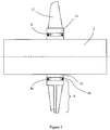
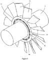
- FIGs 2 and 3 show how a TVA can be implemented practically for use with a rotor shaft 2 of a rotating electrical machine (e.g. a motor or generator).
- the TVA consists of an annular mass 4 supported by a layer of viscoelastic material 6, which acts as a damper, and axially spaced spring assemblies 8a, 8b. Together the spring assemblies 8a, 8b and the viscoelastic material layer 6 form the spring and damper arrangement that is shown schematically in Figure 1 .
- the annular mass 4 is not connected directly to the rotor shaft 2 but is connected to it indirectly by means of the spring assemblies 8a, 8b and the viscoelastic material layer 6.
- Each spring assembly includes a plurality of discrete springs 8c arranged around the radially inner circumference of the annular mass 4 to provide the required axial, torsional and radial stiffnesses.
- the springs 8c are preferably of a fail-safe design so that the annular mass 4 remains secured to the rotor shaft 2 under all conditions.
- the spring assemblies 8a, 8b give good stability against axial forces but have the correct stiffness in the radial direction to enable the TVA to match the first critical speed of the rotor shaft 2.
- the viscoelastic material layer 6 has a relatively high damping characteristic c a to provide resonance control at the two separate critical speeds.
- the viscoelastic material can be a polymer or a plastics material.
- the viscoelastic material layer 6 can be shaped and positioned to provide radial and axial stability in addition to its damping effect.
- the mass M a of the annular mass 4 and the spring rates k a of the springs 8 are chosen according to the mass M of the rotor shaft 2 (and optionally also the mass of the supporting bearings and structures which are not shown) to match the first critical speed of the rotor shaft.
- the annular mass 4 forms part of a rotor air-cooling fan and a plurality of fan blades 12 are integrally mounted to it.
- the springs 8c and the viscoelastic material layer 6 are fixedly secured to an annular flange part 10 of the rotor shaft and to a radially inner surface of an annular root part 14 of the annular mass 4 to which the fan blades 12 are integrally mounted.
- the rotor shaft shown in Figures 2 and 3 can be used as part of a high-speed motor with an operating speed range of 0 to 6600 rpm.
- a conventional rotor shaft for the same motor would have a first critical speed of about 3100 rpm.
- the addition of TV As each with a mass ( M a ) of 57 kg at two axially spaced rotor air-cooling fan positions provides a reduction in structural resonance vibrations of 99.97% at a rotational speed of about 3100 rpm.
- Two new critical speeds are created at about 2600 rpm and about 3700 rpm but the structural resonances at those critical speeds have a magnitude lower than that for the conventional rotor shaft.
- the addition of two axially spaced TV As means that the rotor shaft can meet American Petroluem Institute (API) vibration standards without the need for a more complicated rotor construction.
- API American Petroluem Institute
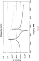
- the vibration magnitude versus operating speed for the conventional rotor shaft is represented in Figure 4 by the dashed line. It shows a maximum vibration magnitude at the first critical speed of about 3100 rpm.
- the vibration magnitude versus operating speed for the rotor shaft that incorporates the TVA is represented in Figure 4 by the solid line. It shows maximum vibration magnitudes at the critical speeds of about 2600 rpm and about 3700 rpm.
Landscapes
- Engineering & Computer Science (AREA)
- General Engineering & Computer Science (AREA)
- Physics & Mathematics (AREA)
- Acoustics & Sound (AREA)
- Aviation & Aerospace Engineering (AREA)
- Mechanical Engineering (AREA)
- Motor Or Generator Frames (AREA)
- Iron Core Of Rotating Electric Machines (AREA)
- Connection Of Motors, Electrical Generators, Mechanical Devices, And The Like (AREA)
Claims (7)
- Rotoranordnung für eine elektrische Maschine, die aufweist:eine drehbare Welle (2) undeinen abgestimmten Schwingungsdämpfer, der enthält:eine im Wesentlichen ringförmige starre Masse (4) undeinen Feder- und Dämpfer-Mechanismus, der die starre Masse (4) mit der drehbaren Welle (2) verbindet;dadurch gekennzeichnet, dass der Feder- und Dämpfer-Mechanismus eine Federanordnung (8a) und eine viskoelastische Materialschicht (6) enthält;wobei die Federanordnung (8a) mehrere in Umfangsrichtung beabstandete diskrete Federn (8c) enthält.
- Rotoranordnung nach Anspruch 1, wobei eine Federkonstante (ka ) der Federanordnung (8a) und die Masse (Ma ) der starren Masse (4) passend zu einer Eigenfrequenz der drehbaren Welle (2) ausgewählt sind.
- Rotoranordnung nach Anspruch 2, wobei die Eigenfrequenz die niedrigste Eigenfrequenz der drehbaren Welle (2) ist.
- Rotoranordnung nach einem beliebigen vorhergehenden Anspruch, wobei eine Dämpfungskonstante (ca ) des Feder- und Dämpfer-Mechanismus ausgewählt ist, um die Antwortgröße der drehbaren Welle (2) zu beschränken.
- Rotoranordnung nach einem beliebigen vorhergehenden Anspruch, wobei das viskoelastische Material (6) ein Polymer oder Kunststoffmaterial ist.
- Rotierende elektrische Maschine, die eine Rotoranordnung nach einem beliebigen vorhergehenden Anspruch enthält.
- Rotierende elektrische Maschine nach Anspruch 6, die ferner eine Statoranordnung aufweist.
Priority Applications (7)
| Application Number | Priority Date | Filing Date | Title |
|---|---|---|---|
| EP10004954.3A EP2386779B1 (de) | 2010-05-11 | 2010-05-11 | Rotoren für elektrische Maschinen |
| PCT/EP2011/002082 WO2011141126A1 (en) | 2010-05-11 | 2011-04-26 | Rotors for electrical machines |
| CN2011800233631A CN103026096A (zh) | 2010-05-11 | 2011-04-26 | 电机的转子 |
| BR112012028889A BR112012028889A2 (pt) | 2010-05-11 | 2011-04-26 | rotores para máquinas elétricas |
| CA2800310A CA2800310A1 (en) | 2010-05-11 | 2011-04-26 | Rotors for electrical machines |
| JP2013509460A JP5934186B2 (ja) | 2010-05-11 | 2011-04-26 | 電気機器用ロータ |
| US13/696,313 US9683628B2 (en) | 2010-05-11 | 2011-04-26 | Vibration damping in rotor assembly |
Applications Claiming Priority (1)
| Application Number | Priority Date | Filing Date | Title |
|---|---|---|---|
| EP10004954.3A EP2386779B1 (de) | 2010-05-11 | 2010-05-11 | Rotoren für elektrische Maschinen |
Publications (2)
| Publication Number | Publication Date |
|---|---|
| EP2386779A1 EP2386779A1 (de) | 2011-11-16 |
| EP2386779B1 true EP2386779B1 (de) | 2018-07-11 |
Family
ID=42782189
Family Applications (1)
| Application Number | Title | Priority Date | Filing Date |
|---|---|---|---|
| EP10004954.3A Not-in-force EP2386779B1 (de) | 2010-05-11 | 2010-05-11 | Rotoren für elektrische Maschinen |
Country Status (7)
| Country | Link |
|---|---|
| US (1) | US9683628B2 (de) |
| EP (1) | EP2386779B1 (de) |
| JP (1) | JP5934186B2 (de) |
| CN (1) | CN103026096A (de) |
| BR (1) | BR112012028889A2 (de) |
| CA (1) | CA2800310A1 (de) |
| WO (1) | WO2011141126A1 (de) |
Families Citing this family (1)
| Publication number | Priority date | Publication date | Assignee | Title |
|---|---|---|---|---|
| WO2026024271A1 (en) * | 2024-07-23 | 2026-01-29 | Siemens Energy Global GmbH & Co. KG | System for reducing vibrations in a rotor |
Family Cites Families (13)
| Publication number | Priority date | Publication date | Assignee | Title |
|---|---|---|---|---|
| GB2153484A (en) * | 1984-01-31 | 1985-08-21 | Ferranti Plc | Resonance damper for a rotating body |
| DE3543544A1 (de) * | 1985-12-10 | 1987-06-11 | Bosch Gmbh Robert | Vorrichtung zur lueftergeraeuschminderung und -daempfung bei drehstromgeneratoren |
| FR2608709A3 (fr) * | 1986-04-22 | 1988-06-24 | Jean Claude Cottin | Amortisseur dynamique de vibrations pour moteur pas a pas |
| JPH0642117Y2 (ja) * | 1989-02-22 | 1994-11-02 | エヌ・オー・ケー・メグラスティック株式会社 | トーショナルダンパ |
| FR2664667B1 (fr) * | 1990-07-12 | 1993-07-16 | Barca Didier | Dispositif d'amortissement de vibrations. |
| US5306123A (en) * | 1993-04-08 | 1994-04-26 | General Electric Company | Noise isolating rotor for air handler motor |
| DE4328153C2 (de) * | 1993-08-21 | 1996-11-28 | Freudenberg Carl Fa | Ringförmiges Maschinenteil und Verfahren zu dessen Herstellung |
| US5485053A (en) * | 1993-10-15 | 1996-01-16 | Univ America Catholic | Method and device for active constrained layer damping for vibration and sound control |
| DE4430036C1 (de) * | 1994-08-24 | 1995-08-24 | Sgf Gmbh & Co Kg | Drehschwingungstilger, insbesondere für den Antriebsstrang von Kraftfahrzeugen |
| DE69636505T2 (de) * | 1995-06-07 | 2007-05-24 | General Electric Co. | Dynamoelektrische Maschine und deren Rotorkonstruktion |
| JP2004060785A (ja) * | 2002-07-30 | 2004-02-26 | Nok Corp | モータ用ダイナミックダンパ |
| JP4363277B2 (ja) * | 2004-08-06 | 2009-11-11 | 株式会社デンソー | エンジンシステム |
| US7709991B2 (en) * | 2005-12-08 | 2010-05-04 | A. O. Smith Corporation | Rotor assembly for an electric machine including a vibration damping member and method of manufacturing same |
-
2010
- 2010-05-11 EP EP10004954.3A patent/EP2386779B1/de not_active Not-in-force
-
2011
- 2011-04-26 BR BR112012028889A patent/BR112012028889A2/pt not_active IP Right Cessation
- 2011-04-26 JP JP2013509460A patent/JP5934186B2/ja not_active Expired - Fee Related
- 2011-04-26 US US13/696,313 patent/US9683628B2/en not_active Expired - Fee Related
- 2011-04-26 CN CN2011800233631A patent/CN103026096A/zh active Pending
- 2011-04-26 WO PCT/EP2011/002082 patent/WO2011141126A1/en not_active Ceased
- 2011-04-26 CA CA2800310A patent/CA2800310A1/en not_active Abandoned
Non-Patent Citations (1)
| Title |
|---|
| None * |
Also Published As
| Publication number | Publication date |
|---|---|
| EP2386779A1 (de) | 2011-11-16 |
| WO2011141126A1 (en) | 2011-11-17 |
| US9683628B2 (en) | 2017-06-20 |
| JP5934186B2 (ja) | 2016-06-15 |
| CN103026096A (zh) | 2013-04-03 |
| BR112012028889A2 (pt) | 2016-07-26 |
| US20130057092A1 (en) | 2013-03-07 |
| CA2800310A1 (en) | 2011-11-17 |
| JP2013526683A (ja) | 2013-06-24 |
Similar Documents
| Publication | Publication Date | Title |
|---|---|---|
| US7648278B2 (en) | High speed aerospace generator resilient mount, combined centering spring and squeeze film damper | |
| EP2218940B1 (de) | Elektrische Drehmaschinen | |
| US8632437B2 (en) | Drive system for a wind turbine | |
| US9279413B2 (en) | Wind turbine | |
| US8786151B1 (en) | Apparatus for maintaining air-gap spacing in large diameter, low-speed motors and generators | |
| EP1895178A2 (de) | Elastischer Träger von einheitlicher Steifheit | |
| ZA200402008B (en) | Flywheel energy storage systems | |
| CN104584389B (zh) | 电机的转子和电机 | |
| EP2199641B1 (de) | Wirbelstromtorsionsdämpfer für Generatoren | |
| WO2010097607A1 (en) | Rotor assembly | |
| EP2378630B1 (de) | Befestigungsanordnung für eine elektrische Maschine | |
| CN102918752B (zh) | 电动设备的振动阻尼 | |
| AU2013349341A1 (en) | Machine with two co-axial rotors | |
| EP2751904B1 (de) | Elektrische maschine mit dämpfungsmitteln | |
| US20200412215A1 (en) | Excitation system | |
| US9683628B2 (en) | Vibration damping in rotor assembly | |
| KR101236075B1 (ko) | 풍력 발전 장치 | |
| WO2012013200A1 (en) | Wind turbine generators | |
| JP7217217B2 (ja) | 永久磁石同期回転電機用回転子、および永久磁石同期回転電機用回転子のバランス調整方法 | |
| US10727724B2 (en) | Electric motor generator system with a plurality of magnet portions abutting an inwardly facing surface of a shaft | |
| US20210359574A1 (en) | Well Damped or Critically Damped Motor | |
| RU2673214C1 (ru) | Установка гребного электродвигателя в корпус подводной лодки | |
| WO2026024271A1 (en) | System for reducing vibrations in a rotor | |
| JP2014053990A (ja) | 回転電機 | |
| CN112751456A (zh) | 发电机及风力发电机组 |
Legal Events
| Date | Code | Title | Description |
|---|---|---|---|
| AK | Designated contracting states |
Kind code of ref document: A1 Designated state(s): AL AT BE BG CH CY CZ DE DK EE ES FI FR GB GR HR HU IE IS IT LI LT LU LV MC MK MT NL NO PL PT RO SE SI SK SM TR |
|
| AX | Request for extension of the european patent |
Extension state: BA ME RS |
|
| PUAI | Public reference made under article 153(3) epc to a published international application that has entered the european phase |
Free format text: ORIGINAL CODE: 0009012 |
|
| 17P | Request for examination filed |
Effective date: 20120503 |
|
| RAP1 | Party data changed (applicant data changed or rights of an application transferred) |
Owner name: GE ENERGY POWER CONVERSION TECHNOLOGY LIMITED |
|
| STAA | Information on the status of an ep patent application or granted ep patent |
Free format text: STATUS: EXAMINATION IS IN PROGRESS |
|
| 17Q | First examination report despatched |
Effective date: 20170109 |
|
| GRAP | Despatch of communication of intention to grant a patent |
Free format text: ORIGINAL CODE: EPIDOSNIGR1 |
|
| STAA | Information on the status of an ep patent application or granted ep patent |
Free format text: STATUS: GRANT OF PATENT IS INTENDED |
|
| INTG | Intention to grant announced |
Effective date: 20180220 |
|
| GRAS | Grant fee paid |
Free format text: ORIGINAL CODE: EPIDOSNIGR3 |
|
| GRAA | (expected) grant |
Free format text: ORIGINAL CODE: 0009210 |
|
| STAA | Information on the status of an ep patent application or granted ep patent |
Free format text: STATUS: THE PATENT HAS BEEN GRANTED |
|
| AK | Designated contracting states |
Kind code of ref document: B1 Designated state(s): AL AT BE BG CH CY CZ DE DK EE ES FI FR GB GR HR HU IE IS IT LI LT LU LV MC MK MT NL NO PL PT RO SE SI SK SM TR |
|
| REG | Reference to a national code |
Ref country code: GB Ref legal event code: FG4D |
|
| REG | Reference to a national code |
Ref country code: CH Ref legal event code: EP |
|
| REG | Reference to a national code |
Ref country code: AT Ref legal event code: REF Ref document number: 1017208 Country of ref document: AT Kind code of ref document: T Effective date: 20180715 |
|
| REG | Reference to a national code |
Ref country code: DE Ref legal event code: R096 Ref document number: 602010051757 Country of ref document: DE |
|
| REG | Reference to a national code |
Ref country code: IE Ref legal event code: FG4D |
|
| REG | Reference to a national code |
Ref country code: NL Ref legal event code: MP Effective date: 20180711 |
|
| REG | Reference to a national code |
Ref country code: LT Ref legal event code: MG4D |
|
| REG | Reference to a national code |
Ref country code: AT Ref legal event code: MK05 Ref document number: 1017208 Country of ref document: AT Kind code of ref document: T Effective date: 20180711 |
|
| PG25 | Lapsed in a contracting state [announced via postgrant information from national office to epo] |
Ref country code: NL Free format text: LAPSE BECAUSE OF FAILURE TO SUBMIT A TRANSLATION OF THE DESCRIPTION OR TO PAY THE FEE WITHIN THE PRESCRIBED TIME-LIMIT Effective date: 20180711 |
|
| PG25 | Lapsed in a contracting state [announced via postgrant information from national office to epo] |
Ref country code: SE Free format text: LAPSE BECAUSE OF FAILURE TO SUBMIT A TRANSLATION OF THE DESCRIPTION OR TO PAY THE FEE WITHIN THE PRESCRIBED TIME-LIMIT Effective date: 20180711 Ref country code: BG Free format text: LAPSE BECAUSE OF FAILURE TO SUBMIT A TRANSLATION OF THE DESCRIPTION OR TO PAY THE FEE WITHIN THE PRESCRIBED TIME-LIMIT Effective date: 20181011 Ref country code: AT Free format text: LAPSE BECAUSE OF FAILURE TO SUBMIT A TRANSLATION OF THE DESCRIPTION OR TO PAY THE FEE WITHIN THE PRESCRIBED TIME-LIMIT Effective date: 20180711 Ref country code: IS Free format text: LAPSE BECAUSE OF FAILURE TO SUBMIT A TRANSLATION OF THE DESCRIPTION OR TO PAY THE FEE WITHIN THE PRESCRIBED TIME-LIMIT Effective date: 20181111 Ref country code: LT Free format text: LAPSE BECAUSE OF FAILURE TO SUBMIT A TRANSLATION OF THE DESCRIPTION OR TO PAY THE FEE WITHIN THE PRESCRIBED TIME-LIMIT Effective date: 20180711 Ref country code: NO Free format text: LAPSE BECAUSE OF FAILURE TO SUBMIT A TRANSLATION OF THE DESCRIPTION OR TO PAY THE FEE WITHIN THE PRESCRIBED TIME-LIMIT Effective date: 20181011 Ref country code: GR Free format text: LAPSE BECAUSE OF FAILURE TO SUBMIT A TRANSLATION OF THE DESCRIPTION OR TO PAY THE FEE WITHIN THE PRESCRIBED TIME-LIMIT Effective date: 20181012 Ref country code: FI Free format text: LAPSE BECAUSE OF FAILURE TO SUBMIT A TRANSLATION OF THE DESCRIPTION OR TO PAY THE FEE WITHIN THE PRESCRIBED TIME-LIMIT Effective date: 20180711 Ref country code: PL Free format text: LAPSE BECAUSE OF FAILURE TO SUBMIT A TRANSLATION OF THE DESCRIPTION OR TO PAY THE FEE WITHIN THE PRESCRIBED TIME-LIMIT Effective date: 20180711 |
|
| PG25 | Lapsed in a contracting state [announced via postgrant information from national office to epo] |
Ref country code: LV Free format text: LAPSE BECAUSE OF FAILURE TO SUBMIT A TRANSLATION OF THE DESCRIPTION OR TO PAY THE FEE WITHIN THE PRESCRIBED TIME-LIMIT Effective date: 20180711 Ref country code: ES Free format text: LAPSE BECAUSE OF FAILURE TO SUBMIT A TRANSLATION OF THE DESCRIPTION OR TO PAY THE FEE WITHIN THE PRESCRIBED TIME-LIMIT Effective date: 20180711 Ref country code: AL Free format text: LAPSE BECAUSE OF FAILURE TO SUBMIT A TRANSLATION OF THE DESCRIPTION OR TO PAY THE FEE WITHIN THE PRESCRIBED TIME-LIMIT Effective date: 20180711 Ref country code: HR Free format text: LAPSE BECAUSE OF FAILURE TO SUBMIT A TRANSLATION OF THE DESCRIPTION OR TO PAY THE FEE WITHIN THE PRESCRIBED TIME-LIMIT Effective date: 20180711 |
|
| REG | Reference to a national code |
Ref country code: DE Ref legal event code: R097 Ref document number: 602010051757 Country of ref document: DE |
|
| PG25 | Lapsed in a contracting state [announced via postgrant information from national office to epo] |
Ref country code: IT Free format text: LAPSE BECAUSE OF FAILURE TO SUBMIT A TRANSLATION OF THE DESCRIPTION OR TO PAY THE FEE WITHIN THE PRESCRIBED TIME-LIMIT Effective date: 20180711 Ref country code: CZ Free format text: LAPSE BECAUSE OF FAILURE TO SUBMIT A TRANSLATION OF THE DESCRIPTION OR TO PAY THE FEE WITHIN THE PRESCRIBED TIME-LIMIT Effective date: 20180711 Ref country code: EE Free format text: LAPSE BECAUSE OF FAILURE TO SUBMIT A TRANSLATION OF THE DESCRIPTION OR TO PAY THE FEE WITHIN THE PRESCRIBED TIME-LIMIT Effective date: 20180711 Ref country code: RO Free format text: LAPSE BECAUSE OF FAILURE TO SUBMIT A TRANSLATION OF THE DESCRIPTION OR TO PAY THE FEE WITHIN THE PRESCRIBED TIME-LIMIT Effective date: 20180711 |
|
| PLBE | No opposition filed within time limit |
Free format text: ORIGINAL CODE: 0009261 |
|
| STAA | Information on the status of an ep patent application or granted ep patent |
Free format text: STATUS: NO OPPOSITION FILED WITHIN TIME LIMIT |
|
| PG25 | Lapsed in a contracting state [announced via postgrant information from national office to epo] |
Ref country code: SM Free format text: LAPSE BECAUSE OF FAILURE TO SUBMIT A TRANSLATION OF THE DESCRIPTION OR TO PAY THE FEE WITHIN THE PRESCRIBED TIME-LIMIT Effective date: 20180711 Ref country code: DK Free format text: LAPSE BECAUSE OF FAILURE TO SUBMIT A TRANSLATION OF THE DESCRIPTION OR TO PAY THE FEE WITHIN THE PRESCRIBED TIME-LIMIT Effective date: 20180711 Ref country code: SK Free format text: LAPSE BECAUSE OF FAILURE TO SUBMIT A TRANSLATION OF THE DESCRIPTION OR TO PAY THE FEE WITHIN THE PRESCRIBED TIME-LIMIT Effective date: 20180711 |
|
| 26N | No opposition filed |
Effective date: 20190412 |
|
| PG25 | Lapsed in a contracting state [announced via postgrant information from national office to epo] |
Ref country code: SI Free format text: LAPSE BECAUSE OF FAILURE TO SUBMIT A TRANSLATION OF THE DESCRIPTION OR TO PAY THE FEE WITHIN THE PRESCRIBED TIME-LIMIT Effective date: 20180711 |
|
| REG | Reference to a national code |
Ref country code: CH Ref legal event code: PL |
|
| PG25 | Lapsed in a contracting state [announced via postgrant information from national office to epo] |
Ref country code: MC Free format text: LAPSE BECAUSE OF FAILURE TO SUBMIT A TRANSLATION OF THE DESCRIPTION OR TO PAY THE FEE WITHIN THE PRESCRIBED TIME-LIMIT Effective date: 20180711 Ref country code: LI Free format text: LAPSE BECAUSE OF NON-PAYMENT OF DUE FEES Effective date: 20190531 Ref country code: CH Free format text: LAPSE BECAUSE OF NON-PAYMENT OF DUE FEES Effective date: 20190531 |
|
| REG | Reference to a national code |
Ref country code: BE Ref legal event code: MM Effective date: 20190531 |
|
| PG25 | Lapsed in a contracting state [announced via postgrant information from national office to epo] |
Ref country code: LU Free format text: LAPSE BECAUSE OF NON-PAYMENT OF DUE FEES Effective date: 20190511 |
|
| PG25 | Lapsed in a contracting state [announced via postgrant information from national office to epo] |
Ref country code: TR Free format text: LAPSE BECAUSE OF FAILURE TO SUBMIT A TRANSLATION OF THE DESCRIPTION OR TO PAY THE FEE WITHIN THE PRESCRIBED TIME-LIMIT Effective date: 20180711 |
|
| PG25 | Lapsed in a contracting state [announced via postgrant information from national office to epo] |
Ref country code: IE Free format text: LAPSE BECAUSE OF NON-PAYMENT OF DUE FEES Effective date: 20190511 |
|
| PG25 | Lapsed in a contracting state [announced via postgrant information from national office to epo] |
Ref country code: BE Free format text: LAPSE BECAUSE OF NON-PAYMENT OF DUE FEES Effective date: 20190531 |
|
| PG25 | Lapsed in a contracting state [announced via postgrant information from national office to epo] |
Ref country code: PT Free format text: LAPSE BECAUSE OF FAILURE TO SUBMIT A TRANSLATION OF THE DESCRIPTION OR TO PAY THE FEE WITHIN THE PRESCRIBED TIME-LIMIT Effective date: 20181111 |
|
| PGFP | Annual fee paid to national office [announced via postgrant information from national office to epo] |
Ref country code: FR Payment date: 20200422 Year of fee payment: 11 Ref country code: DE Payment date: 20200421 Year of fee payment: 11 |
|
| PGFP | Annual fee paid to national office [announced via postgrant information from national office to epo] |
Ref country code: GB Payment date: 20200423 Year of fee payment: 11 |
|
| PG25 | Lapsed in a contracting state [announced via postgrant information from national office to epo] |
Ref country code: CY Free format text: LAPSE BECAUSE OF FAILURE TO SUBMIT A TRANSLATION OF THE DESCRIPTION OR TO PAY THE FEE WITHIN THE PRESCRIBED TIME-LIMIT Effective date: 20180711 |
|
| PG25 | Lapsed in a contracting state [announced via postgrant information from national office to epo] |
Ref country code: HU Free format text: LAPSE BECAUSE OF FAILURE TO SUBMIT A TRANSLATION OF THE DESCRIPTION OR TO PAY THE FEE WITHIN THE PRESCRIBED TIME-LIMIT; INVALID AB INITIO Effective date: 20100511 Ref country code: MT Free format text: LAPSE BECAUSE OF FAILURE TO SUBMIT A TRANSLATION OF THE DESCRIPTION OR TO PAY THE FEE WITHIN THE PRESCRIBED TIME-LIMIT Effective date: 20180711 |
|
| REG | Reference to a national code |
Ref country code: DE Ref legal event code: R119 Ref document number: 602010051757 Country of ref document: DE |
|
| GBPC | Gb: european patent ceased through non-payment of renewal fee |
Effective date: 20210511 |
|
| PG25 | Lapsed in a contracting state [announced via postgrant information from national office to epo] |
Ref country code: GB Free format text: LAPSE BECAUSE OF NON-PAYMENT OF DUE FEES Effective date: 20210511 Ref country code: DE Free format text: LAPSE BECAUSE OF NON-PAYMENT OF DUE FEES Effective date: 20211201 |
|
| PG25 | Lapsed in a contracting state [announced via postgrant information from national office to epo] |
Ref country code: FR Free format text: LAPSE BECAUSE OF NON-PAYMENT OF DUE FEES Effective date: 20210531 |
|
| PG25 | Lapsed in a contracting state [announced via postgrant information from national office to epo] |
Ref country code: MK Free format text: LAPSE BECAUSE OF FAILURE TO SUBMIT A TRANSLATION OF THE DESCRIPTION OR TO PAY THE FEE WITHIN THE PRESCRIBED TIME-LIMIT Effective date: 20180711 |