EP2386818A1 - Dispositif à l'exploration d'environs pour un véhicule et procédure de sa production - Google Patents
Dispositif à l'exploration d'environs pour un véhicule et procédure de sa production Download PDFInfo
- Publication number
- EP2386818A1 EP2386818A1 EP10004930A EP10004930A EP2386818A1 EP 2386818 A1 EP2386818 A1 EP 2386818A1 EP 10004930 A EP10004930 A EP 10004930A EP 10004930 A EP10004930 A EP 10004930A EP 2386818 A1 EP2386818 A1 EP 2386818A1
- Authority
- EP
- European Patent Office
- Prior art keywords
- observation point
- vehicle
- roof
- carrier
- observation
- Prior art date
- Legal status (The legal status is an assumption and is not a legal conclusion. Google has not performed a legal analysis and makes no representation as to the accuracy of the status listed.)
- Withdrawn
Links
- 238000004519 manufacturing process Methods 0.000 title claims abstract description 5
- 239000011521 glass Substances 0.000 claims abstract description 12
- 239000012780 transparent material Substances 0.000 claims abstract description 7
- 239000000919 ceramic Substances 0.000 claims abstract description 4
- 239000000463 material Substances 0.000 claims description 9
- 238000005474 detonation Methods 0.000 claims description 3
- 238000004026 adhesive bonding Methods 0.000 claims description 2
- 230000007613 environmental effect Effects 0.000 claims 1
- 238000011835 investigation Methods 0.000 claims 1
- 238000000034 method Methods 0.000 abstract description 3
- 238000009434 installation Methods 0.000 description 4
- 230000000694 effects Effects 0.000 description 2
- 238000004880 explosion Methods 0.000 description 2
- 125000002066 L-histidyl group Chemical group [H]N1C([H])=NC(C([H])([H])[C@](C(=O)[*])([H])N([H])[H])=C1[H] 0.000 description 1
- 229920005372 Plexiglas® Polymers 0.000 description 1
- 206010038743 Restlessness Diseases 0.000 description 1
- 229910000831 Steel Inorganic materials 0.000 description 1
- 239000000853 adhesive Substances 0.000 description 1
- 230000001070 adhesive effect Effects 0.000 description 1
- 239000004926 polymethyl methacrylate Substances 0.000 description 1
- 238000002360 preparation method Methods 0.000 description 1
- 230000001681 protective effect Effects 0.000 description 1
- 239000010959 steel Substances 0.000 description 1
- 230000004083 survival effect Effects 0.000 description 1
- XLYOFNOQVPJJNP-UHFFFAOYSA-N water Substances O XLYOFNOQVPJJNP-UHFFFAOYSA-N 0.000 description 1
Images




Classifications
-
- F—MECHANICAL ENGINEERING; LIGHTING; HEATING; WEAPONS; BLASTING
- F41—WEAPONS
- F41H—ARMOUR; ARMOURED TURRETS; ARMOURED OR ARMED VEHICLES; MEANS OF ATTACK OR DEFENCE, e.g. CAMOUFLAGE, IN GENERAL
- F41H7/00—Armoured or armed vehicles
- F41H7/02—Land vehicles with enclosing armour, e.g. tanks
- F41H7/04—Armour construction
-
- F—MECHANICAL ENGINEERING; LIGHTING; HEATING; WEAPONS; BLASTING
- F41—WEAPONS
- F41H—ARMOUR; ARMOURED TURRETS; ARMOURED OR ARMED VEHICLES; MEANS OF ATTACK OR DEFENCE, e.g. CAMOUFLAGE, IN GENERAL
- F41H5/00—Armour; Armour plates
- F41H5/26—Peepholes; Windows; Loopholes
Definitions
- the present invention relates to an environment-sensing device for a vehicle, in particular for an armored vehicle, comprising a floor section arranged at the floor of the vehicle, at least one armored side section arranged at the side of the vehicle and an armored roof plane is arranged on a roof portion of the vehicle and a method for their preparation.
- Vehicles with observation points have different uses. In an armored version, such vehicles serve to provide a secure observation space. Especially in places where unrest prevails, armed conflicts take place or there is another danger potential, there is a great need for vehicles that provide the occupants with sufficient security without impairing their activity. Unpulled such vehicles u. a. also used for hunting purposes. From the prior art, only vehicles are known which have a permanently mounted on the roof of the vehicle observatory. On the one hand, these types of observation points offer very limited viewing possibilities and, since they are firmly installed in the vehicle roof, are easy to notice, which represents a decisive disadvantage in critical cases. Furthermore, fold-out Dachauf- or -ausbauten are known.
- the invention is therefore based on the object to show a way as in or on a vehicle of the type mentioned in a simple manner and with relatively little Expenditure a space to ensure the greatest possible visibility with optimal protection of the occupants can be formed.
- This invention is based on the idea that a vehicle of at least one floor section, which is arranged at the bottom of the vehicle, at least one armored side section, which is arranged on the side of the vehicle, and an armored roof level, which is arranged on a roof portion of the vehicle , wherein in the region of the roof section at least one by at least one attached to a carrier device translationally movable observation point is arranged and the observation point is formed at least in one piece and the observation point is formed of a transparent material.
- This allows a better and safer observation of the environment, resulting in increased safety of the occupants of the vehicle.
- the user of the observation point of the vehicle has a 360-degree all-round view through a transparent, protective material according to the invention.
- the observation site is designed to be movable, so it can be moved in and out.
- the observation point can be retracted so far into the vehicle that it is not visible from the outside. It is therefore not possible to tell if it is an armored vehicle.
- the observation point can be integrally formed to reduce effort and costs.
- the device attached to the carrier is a fastening and / or lifting device through which the observation point is axially fixed.
- fastening and / or lifting device of the observation point according to the invention is attached to the carrier.
- the observation point can be moved in and out.
- the carrier is within or completely or partially outside the vehicle, in particular in the region of Roof section formed.
- the different installation methods make it possible to attach the device according to the needs of the vehicle. This includes both new designs and retrofits of existing vehicles.
- the observation point is preferably arranged in the roof section to allow the widest possible field of view.
- the vertical position of the observation point is variable by the lifting device, wherein the lifting device acts electrically and / or hydraulically and / or mechanically and / or pneumatically and / or is manually operable.
- the observation point can be moved in and out without or with little effort. Manual operation in case of danger is alternatively possible.
- the vertical movement distance of the observation point is in the range of 10 cm to 200 cm, in particular between 10 cm and 50 cm, wherein the bottom element of the observation point is always at least partially in the carrier. This ensures that the observant person can perform his / her activity kneeling, sitting and standing while ensuring personal safety at all times.
- the observation point can be moved far enough to allow the best possible view.
- the observation point is formed immovably on the roof section, wherein the lifting device is replaced by a fixed support. This allows even faster and cheaper production.
- the observation point is designed in the form of a hollow body such as a cuboid and / or a dome and / or a truncated pyramid and / or a cylinder and / or a pyramid and / or a cone and / or a truncated cone and / or a pediment, which is a Opening has downwards.
- a hollow body such as a cuboid and / or a dome and / or a truncated pyramid and / or a cylinder and / or a pyramid and / or a cone and / or a truncated cone and / or a pediment, which is a Opening has downwards.
- connection means at least one connection point positively and / or non-positively and / or materially connectable.
- the side elements and the roof element of the observation point by means of screws and / or gluing and / or riveting and / or folding can be connected.
- this can be a form-fitting and secure connection.
- At least one seal is provided between the observation site and the carrier. This prevents the ingress of dirt and water into the interior and weakens the pressure wave of a detonation.
- the observation site and / or the carrier on a telescope mechanism This allows a more compact and thus space-saving design with the same maximum height.
- the observation point and the part of the carrier formed above the armored roof section are formed from a material with which the pressure wave of a detonation and / or a shot and / or an impact can be derived.
- the observation point is formed of a glass and / or ceramic glass.
- an area of the observation point is formed as an existing from an opening and closing emergency exit.
- This can be both a door designed as part of the observation point and a device which allows the folding up or down and / or the removal of the complete observation point.
- the emergency exit offers the vehicle occupants a way to leave their vehicle in case of danger, which, especially in armored vehicles, which are very difficult to open in the event of damage to auxiliaries, the chances of survival injured People increased.
- the observation point can be trained without emergency exit.
- At least one measuring and / or observation and / or transmitting and / or receiving device is arranged inside the observation point. This offers users such as reporters in crisis areas a protected communication and recording option. Furthermore, the sensors of autonomous vehicles can be placed there.
- the roof portion of the vehicle is usable as a carrier, wherein at least a part of the observation point is disposed at a position inside the roof portion. This allows both a faster and cheaper production and a more compact design.
- Fig. 1 is a schematic side view of a vehicle 1 with the observation point 2 according to the invention shown.
- the vehicle 1 is composed of a floor portion 6 disposed on the floor of the vehicle 1, an armored side portion 5 disposed on the side of the vehicle 1, and an armored roof portion 4 disposed on the roof of the vehicle 1 and an observation point 2 , which is arranged in the region of the roof section 4.
- the observation point 2 is used by a person 3 located in the vehicle 1.
- Fig. 2 schematically shows the structure of an observation point according to the invention.
- the observation point 2 consists of a roof element 14 and a parallel bottom element 9 and four perpendicular side elements 13 which are arranged at right angles to each other and with the roof element 14 and the bottom element 9 form a hollow body 26 in the form of a cuboid 18 having an opening 26th downwards.
- the side members 13 are connected to the roof member 14 and the bottom member 9 respectively at the evenly distributed over the circumference joints 15.
- the side surfaces are made of a transparent material 17, which serves to allow the observer the widest possible view. Furthermore, the interior of the vehicle is thereby protected against external attacks, such as explosions or bullets. It is therefore a particularly robust material such as tank or ceramic glass to use.
- the roof element 14 is made of an armored material, including the use of a transparent material such as glass or bulletproof glass is possible.
- the bottom element 9 of the observation point 2 is guided in a carrier 7 in the vertical direction.
- the carrier 7 is made of a ball and explosion-proof material, such as armored steel, formed and positively, materially and / or non-positively attached to or in the roof of a vehicle, not shown.
- a seal for example a box-bar seal.
- a fastening and lifting device 8 is arranged, which acts on the bottom element 9 and fixes the observation point 2 in the axial direction. It may be a mechanical, pneumatic, electrical or hydraulic system, or a hybrid system. As a result, the observation point 2 is moved in the vertical direction and thus retracted and extended.
- the Observationstelle can be moved manually, for example, in emergencies. The movement distance is, depending on the height of the observation point 2, between 10 cm and 200 cm, in particular between 10 cm and 50 cm
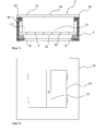
- FIG. 3 shows the observation point 2 according to the invention FIG. 2 in retracted state.
- the observation site 2 is retracted by an adjustment of the fixed to the carrier 7 fastening and lifting device 8 in the vertical direction in the carrier 7.
- the roof element 14 is in contact with the carrier 7. With flush installation, the roof element 14 of the observation point 2 is no longer visible from the outside.
- Fig. 4 represents a plan view of the observation point 2 of the invention from the Figures 2 and 3
- an opening and closing point 23 is designed as an emergency exit 24.
- the emergency exit 24 can be opened manually.
- FIG. 2 illustrates the side view of a one-piece observation point 2 designed as a dome 19. Between the observation point 2 and the carrier 7, a seal 16 is attached. The integrally formed observation point 2 is frictionally engaged, positive and / or material fit, for example by means of adhesive, attachable to the fastening and lifting device.
- Observation point 2 consists of a bulletproof glass. It can also consist of a transparent, non-armored material, such as Plexiglas.
- Fig. 6 shows a plan view of the observation station 2 according to the invention Fig. 5 ,
- the Observationstelle is integrally formed and consists of glass.
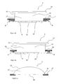
- Fig. 7 is a schematic side view of an observation point of the third embodiment shown.
- the invention shown here, truncated pyramidal observation point 2, the carrier 7 and the fastening and lifting device 8 have the same structure as the structure in Fig. 2 shown cuboid observation point.
- the observation site 2 is designed in the form of a truncated pyramid 20 adapted to the human upper body. Between base element 9 and carrier 7, a seal 16 is attached.
- Fig. 8 is a schematic plan view of the observation of the Fig. 7 shown.
- an opening and closing point 23 is designed as an emergency exit 24. In an emergency, the emergency exit 24 can be opened manually.
- Fig. 9 is a schematic side view of an observation point of the fourth embodiment shown.
- the observation point 2 according to the invention shown here in the form of a cuboid 18 and the fastening and lifting device 8 have the same structure as that in FIG Fig. 2 shown cuboid observation point.
- the observation point 2 shown here can also be embodied in other shapes, for example cylindrical.
- the carrier 7 has the form of a, adapted to the shape of the observation point 2 telescopic tube 22 wherein the individual segments have drivers 10, which allow an inventive retraction and extension.
- FIG. 10 is a schematic side view of an observation point of the fifth embodiment shown.
- the observation point 2 according to the invention shown here in the form of a cylinder 21 is arranged in a carrier 7 and via a Attachment and lifting device 8 connected to this.
- the fastening and lifting device 8 is arranged at the level of the observation point 2 outside the carrier.
- the bottom element 9 of the observation point 2 is extended and connected to the fastening and lifting device 8.
- FIG. 11 is a schematic side view of an observation point of the sixth embodiment shown.
- the observation point 2 according to the invention shown here in the form of a cylinder 21, the carrier 7 and the fastening and lifting device 8 have the same structure as that in FIG Fig. 10 shown cylindrical Observationsstelle on.
- the fastening and lifting devices 8 are mounted directly on the armored roof level 12 without the use of a carrier, which thereby assumes the functions of the carrier.
- Fig. 12 is a schematic side view of an observation point of the seventh embodiment shown.
- the observation point 2 in the form of a dome 19 is formed of a transparent material 17, for example armored or unarmored glass, and has an opening 26 at the bottom. It is fixed by supports 25 on the armored roof level 12.
- Fig. 13 is a schematic side view of a vehicle with built-in cuboid Observationsstelle the Fig. 2 shown.
- the carrier 7 is arranged on the armored roof level 12.
- the roof section 4 of the vehicle 1 is raised to the top of the carrier so that a cavity 11 results.
- Fig. 14 is a schematic side view of a vehicle with built-in cuboid Observationsstelle the Fig. 2 shown.
- the carrier 7 is arranged on the armored roof level 12.
- an observation point 2 may include, inter alia, passenger cars of various design, inter alia, but not exclusively SUV, SUV, sedan, station wagon, each armored and unarmored, a truck, a tractor, a military or civilian special vehicle, a tank, a rail and watercraft and a stationary object act like a military container.
- An observation point can also be designed as a cone, truncated cone, pyramid, gable or in another, not shown here geometric shape.
- Observation Point 2 is mainly used by security and media personnel and also by hunters.
Landscapes
- Engineering & Computer Science (AREA)
- General Engineering & Computer Science (AREA)
- Aiming, Guidance, Guns With A Light Source, Armor, Camouflage, And Targets (AREA)
Priority Applications (1)
| Application Number | Priority Date | Filing Date | Title |
|---|---|---|---|
| EP10004930A EP2386818A1 (fr) | 2010-05-10 | 2010-05-10 | Dispositif à l'exploration d'environs pour un véhicule et procédure de sa production |
Applications Claiming Priority (1)
| Application Number | Priority Date | Filing Date | Title |
|---|---|---|---|
| EP10004930A EP2386818A1 (fr) | 2010-05-10 | 2010-05-10 | Dispositif à l'exploration d'environs pour un véhicule et procédure de sa production |
Publications (1)
| Publication Number | Publication Date |
|---|---|
| EP2386818A1 true EP2386818A1 (fr) | 2011-11-16 |
Family
ID=42733762
Family Applications (1)
| Application Number | Title | Priority Date | Filing Date |
|---|---|---|---|
| EP10004930A Withdrawn EP2386818A1 (fr) | 2010-05-10 | 2010-05-10 | Dispositif à l'exploration d'environs pour un véhicule et procédure de sa production |
Country Status (1)
| Country | Link |
|---|---|
| EP (1) | EP2386818A1 (fr) |
Cited By (1)
| Publication number | Priority date | Publication date | Assignee | Title |
|---|---|---|---|---|
| EP3660443A1 (fr) * | 2018-11-28 | 2020-06-03 | CMI Defence S.A. | Tourelle avec toit de protection escamotable |
Citations (3)
| Publication number | Priority date | Publication date | Assignee | Title |
|---|---|---|---|---|
| DE1703221A1 (de) * | 1968-04-19 | 1971-04-15 | Porsche Kg | Kampffahrzeug mit einer Sichtkuppel |
| FR2218543A1 (fr) * | 1973-02-21 | 1974-09-13 | Riffet Marcel | |
| US20090120274A1 (en) * | 2007-11-10 | 2009-05-14 | John Schneider | Vehicle protective structure |
-
2010
- 2010-05-10 EP EP10004930A patent/EP2386818A1/fr not_active Withdrawn
Patent Citations (3)
| Publication number | Priority date | Publication date | Assignee | Title |
|---|---|---|---|---|
| DE1703221A1 (de) * | 1968-04-19 | 1971-04-15 | Porsche Kg | Kampffahrzeug mit einer Sichtkuppel |
| FR2218543A1 (fr) * | 1973-02-21 | 1974-09-13 | Riffet Marcel | |
| US20090120274A1 (en) * | 2007-11-10 | 2009-05-14 | John Schneider | Vehicle protective structure |
Cited By (4)
| Publication number | Priority date | Publication date | Assignee | Title |
|---|---|---|---|---|
| EP3660443A1 (fr) * | 2018-11-28 | 2020-06-03 | CMI Defence S.A. | Tourelle avec toit de protection escamotable |
| WO2020108976A1 (fr) * | 2018-11-28 | 2020-06-04 | Cmi Defence S.A. | Tourelle avec toit de protection escamotable |
| US11454476B2 (en) | 2018-11-28 | 2022-09-27 | Cmi Defence S.A. | Turret with retractable protective roof |
| EP4339550A3 (fr) * | 2018-11-28 | 2024-05-15 | John Cockerill Defense SA | Tourelle avec toit de protection escamotable |
Similar Documents
| Publication | Publication Date | Title |
|---|---|---|
| EP1564519B1 (fr) | Véhicule ayant une construction contre les mines terrestres | |
| AT413445B (de) | Minengeschützte fahrzeugwannenbodenstruktur | |
| DE102011000974A1 (de) | Fahrzeug, insbesondere militärisches Fahrzeug | |
| DE102018107296A1 (de) | Aktiver überrollschutz | |
| DE102007036393A1 (de) | Beweglicher und vorzugsweise abnehmbarer SLAT-Schutzaufbau für Fahrzeuge | |
| DE102022124290A1 (de) | Dachmodul zur Bildung eines Fahrzeugdachs | |
| DE102018124354A1 (de) | Zugangssystem für ein Fahrzeug, Verfahren für ein Zugangssystem, Computerprogrammprodukt und computerlesbares Medium | |
| DE102010050716A1 (de) | Mast | |
| DE3518551C2 (fr) | ||
| EP2386818A1 (fr) | Dispositif à l'exploration d'environs pour un véhicule et procédure de sa production | |
| DE102017011968A1 (de) | Vorrichtung zum Schutz von Batteriemodulen in einem Kraftfahrzeug | |
| DE102010020006A1 (de) | Vorrichtung zur Umgebungserkundung für ein Fahrzeug und Verfahren zu deren Herstellung | |
| EP0615109A1 (fr) | Véhicule blindé muni d'un toit de protection mobile | |
| EP3018442B1 (fr) | Recouvrement de protection d'un élément de protection | |
| DE102012001995A1 (de) | Fahrzeug mit einem Zwischenboden | |
| EP2120001B1 (fr) | Véhicule blindé avec trou d'homme fermable par un couvercle | |
| DE102007026545A1 (de) | Schutzverkleidung für ein Fahrzeug | |
| DE102010047271A1 (de) | Sicherheitseinrichtung eines Fahrzeugs | |
| DE10159300B4 (de) | Vorrichtung zum Verhindern von Karosserieschäden an einem Fahrzeug | |
| DE7806140U1 (de) | Kugelsichere panzervorrichtung fuer fahrzeugfenster und/oder fahrzeugtueren | |
| DE102006045991A1 (de) | Geschützte Infanteriekabine bevorzugt für den Häuserkampf insbesondere in urbanen Gebieten | |
| DE102014220703A1 (de) | Anordnung im Bereich eines Montageträgers im Vorderwagen eines Kraftfahrzeuges | |
| EP1757900B1 (fr) | Dispositif de protection contre charges explosives | |
| WO2024160725A1 (fr) | Boîtier de dispositif de mesure pour fixation à un moyen de transport | |
| DE102008049933A1 (de) | Minenschutz-Sitzüberzug für Fahrzeugsitze |
Legal Events
| Date | Code | Title | Description |
|---|---|---|---|
| 17P | Request for examination filed |
Effective date: 20100609 |
|
| AK | Designated contracting states |
Kind code of ref document: A1 Designated state(s): AL AT BE BG CH CY CZ DE DK EE ES FI FR GB GR HR HU IE IS IT LI LT LU LV MC MK MT NL NO PL PT RO SE SI SK SM TR |
|
| AX | Request for extension of the european patent |
Extension state: BA ME RS |
|
| PUAI | Public reference made under article 153(3) epc to a published international application that has entered the european phase |
Free format text: ORIGINAL CODE: 0009012 |
|
| 17Q | First examination report despatched |
Effective date: 20120926 |
|
| STAA | Information on the status of an ep patent application or granted ep patent |
Free format text: STATUS: THE APPLICATION IS DEEMED TO BE WITHDRAWN |
|
| 18D | Application deemed to be withdrawn |
Effective date: 20151201 |