EP2386879A2 - Neutronenbilddetektionsverfahren und das Verfahren nutzender Neutronenbilddetektor - Google Patents
Neutronenbilddetektionsverfahren und das Verfahren nutzender Neutronenbilddetektor Download PDFInfo
- Publication number
- EP2386879A2 EP2386879A2 EP11001589A EP11001589A EP2386879A2 EP 2386879 A2 EP2386879 A2 EP 2386879A2 EP 11001589 A EP11001589 A EP 11001589A EP 11001589 A EP11001589 A EP 11001589A EP 2386879 A2 EP2386879 A2 EP 2386879A2
- Authority
- EP
- European Patent Office
- Prior art keywords
- neutron
- photon
- count
- fluorescent light
- signal
- Prior art date
- Legal status (The legal status is an assumption and is not a legal conclusion. Google has not performed a legal analysis and makes no representation as to the accuracy of the status listed.)
- Granted
Links
Images

















Classifications
-
- G—PHYSICS
- G01—MEASURING; TESTING
- G01T—MEASUREMENT OF NUCLEAR OR X-RADIATION
- G01T3/00—Measuring neutron radiation
- G01T3/06—Measuring neutron radiation with scintillation detectors
Definitions
- the present invention relates to a neutron image detecting method for creating one-dimensional or two-dimensional neutron images at a high speed and with increased position accuracy, and relates to a neutron image detector using this method.
- the present invention can be applied to various purposes for the measurement of intense pulsed neutrons in a high-intensity photon accelerator facility (e.g. J-PARC), the evaluation of various dynamic behaviors in nuclear reactors and fusion reactors, the non-destructive inspection using high permeability of neutrons, and the physical property measurement of new materials.
- a high-intensity photon accelerator facility e.g. J-PARC
- the two-dimensional neutron image detector used for neutron scattering experiments using neutron sources generated by a nuclear reactor or an accelerator what have been used include such a detector as being formed by combining a neutron scintillator or a fluorescent neutron detecting sheet formed together with a fluorescent material and a neutron convertor with a wavelength shifting fiber (refer to Patent Literatures 1 and 2, and Non-Patent Literature 1).
- Such two-dimensional image detector is characterized in that the position information is obtained by using a cross-fiber reading method, including proven methods such as a method for determining the incident position by using a coincidence counting method using such a sheet configuration that a couple of wavelength shifting fiber bundles are arranged diagonally on the upper surface and the bottom surface of the fluorescent material sheet or the scintillator plate, a method for determining the incident position by using a coincidence counting method using such a sheet configuration that couple of wavelength shifting fiber bundles are arranged diagonally on the back surface of the scintillator by improving the cross-fiber reading method, and a method using such a sheet configuration that a couple of wavelength shifting fiber bundles are arranged diagonally and that scintillators are arranged on its upper surface and bottom surface.
- a cross-fiber reading method including proven methods such as a method for determining the incident position by using a coincidence counting method using such a sheet configuration that a couple of wavelength shifting fiber bundles are arranged diagonally on the upper surface and the bottom surface of the fluorescent material sheet or the
- Anger-type camera method uses such a method in that gamma-rays or fluorescent lights from the neutron scintillator are detected directly by a number of photomultiplier tubes, and the incident position is determined by a median point calculating method on the basis of the digitized values of the fluorescent light intensity by using Analog/Digital Converter (hereinafter referred to as ADC) (for example, refer to Patent Literature 3).
- ADC Analog/Digital Converter
- the fluorescent light emitted from the scintillator is converted to the electric signal by the photomultiplier tube, and then the analog pulse signal is output after amplifying the integrated signal waveform by using the waveform shaping amplifier, and the peak value of the obtained analog pulse signal waveform is digitized, and the position showing the maximum value at the corresponding optical fiber or wavelength shifting fiber is finally determined to be the incident position.
- the analog pulse signal is output after amplifying the integrated signal waveform by using the waveform shaping amplifier, and the peak value of the obtained analog pulse signal waveform is digitized, and the position showing the maximum value at the corresponding optical fiber or wavelength shifting fiber is finally determined to be the incident position.
- one-dimensional neutron image is obtained in that the fluorescent light emitted from the scintillators each separated at regular intervals by reflecting plates are made led into the photomultiplier tubes by using the optical fibers, and then the signal induced by the fluorescent light is made integrated, and finally the signal having a signal value equal to or larger than the predetermined value is counted to be identifying a single neutron incident.
- the light transmission efficiency is several percent when the fluorescent light emitted from the scintillator is transmitted through the wavelength shifting fiber or the optical fiber to the photomultiplier tube. This requires a number of photons sufficiently enough to shape and amplify the waveform of the signal from the photomultiplier tube, and convert the amplified waveform into the digital signal by using ADC circuit, which may lead to such a disadvantage that the detection efficiency for neutrons decreases.
- One aspect of the neutron image detection method or the neutron image detector based on this method according to the present invention is based on the concept in that, in the neutron image detection method for collecting a fluorescent light generated by a neutron incident at a designated position interval in one-dimensional geometry and determining an incident position of the neutron by detecting the collected fluorescent light, wherein the fluorescent light is detected by photon counting method; a pulse signal generated by an individual output photon is extracted on the basis of a clock signal generated with the same time interval as the time width of the pulse signal generated by a single photon; a count-value distribution is obtained in terms of incident position as variable determined by a single neutron incident by counting the pulse signal output; a neutron incident position is determined by calculating a median point on the basis of the obtained count-value distribution.
- Another aspect of the neutron image detection method or the neutron image detector based on this method according to the present invention is based on the concept in that, in the neutron image detection method for collecting a fluorescent light generated by a neutron incident at a designated position interval on a vertical axis and a horizontal axis, respectively, in two-dimensional geometry and determining an incident position of the neutron by detecting the collected fluorescent light, wherein the fluorescent light is detected by photon counting method; a pulse signal generated by an individual photon is extracted on the basis of a clock signal generated with the same time interval as the time width of the pulse signal generated by a single photon; a count-value distribution is obtained on a vertical axis and a horizontal axis, respectively, in terms of incident position as variable determined by a single neutron incident by counting the pulse signal output; a neutron incident position is determined on a vertical axis and a horizontal axis, respectively, by calculating a median point on a vertical axis and a horizontal axis, respectively, on the basis
- the neutron image detection method for collecting a fluorescent light from a scintillator generating a fluorescent light upon a neutron incident at a designated position interval on a vertical axis and a horizontal axis, respectively, in two-dimensional geometry and determining an incident position of the neutron by detecting the collected fluorescent light or detecting the fluorescent light directly in two-dimensional geometry wherein the fluorescent light is detected by photon counting method; a pulse signal generated by an individual photon is extracted on the basis of a clock signal generated with the same time interval as the time width of the pulse signal generated by a single photon; a two-dimensional count-value distribution is obtained in terms of incident position as variable determined by a single neutron incident by counting the pulse signal output, or obtained by detecting directly the fluorescent light; a neutron incident position is determined on a vertical axis and a horizontal axis, respectively, on the basis of the obtained two-
- the above described position calculation can be performed in an extremely high speed by applying exactly FPGA (Field Programmable Gate Array) having a relatively large number of input pins, enabled by today's progressive integrated-circuit technologies.
- FPGA Field Programmable Gate Array
- the incident position of neutron can be determined precisely.
- the neutron image detection method and detector according to the present invention include a sophisticated scheme for calculating the incident position of neutron, it will be appreciated that such a large number of expensive Analog/Digital Converters (ADC) as found in the prior art may not be used, but that the such scheme may be realized by a small-sized, inexpensive and dedicated hardware device.
- ADC Analog/Digital Converters
- the neutron image detector according to the present invention may be significantly inexpensive, and also that the performance speed for creating the neutron image may be significantly fast.
- FIG. 1 illustrates a schematic diagram showing the configuration of the median point calculating circuit in the one-dimensional neutron image detector using a scintillator and a wavelength shifting fiber.
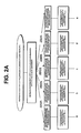
- FIG. 2A and FIG. 2B show flow charts of the median point calculation in case that the generated fluorescent light incident into five wavelength shifting fibers upon the incidence of a neutron.
- A represents the first half of the whole flow chart
- B represents the last half of the flow chart of the whole flow chart. Note that the end raw of blocks of the flow chart A are found as the first raw of blocks of the flow chart B in order to make it easier to understand the connectivity between the first half and the last half of the whole flow chart.
- FIG. 3 illustrates an illustrative diagram showing the calculation example of the median point calculation based on the basic principle of the present invention.
- the one-dimensional neutron image detector using a scintillator and a wavelength shifting fiber in this embodiment has the structure shown below.
- ZnS:Ag/ 10 B 2 O 3 scintillator having a thickness of 0.3mm is used as the neutron scintillator that emits the fluorescent light upon the incidence of a neutron.
- the wavelength of the fluorescent light emitted from ZnS:Ag-based fluorescent material has distributed from 390nm to 520nm, of which the center is 450nm.
- the life-time of the short life-time component of the fluorescent light from ZnS:Ag-based fluorescent material to be used for detecting neutrons substantially is about 0.3 ⁇ s.
- the wavelength shirting fiber is used as the wavelength shirting fiber.
- the shape of the wavelength shifting fiber is made in a right square having one side length of 0.5mm.
- the one-dimensional neutron image detector having the effective sensing width of 32mm is formed by arranging 64 wavelength shifting fibers in one-dimensional geometry, and by arranging ZnS:Ag/ 10 B 2 O 3 scintillator above a bundle of those wavelength shifting fibers.
- H7546 commercially available from HAMAMATSU PHOTONICS K.K. may be used, that is a 64-channnel photomultiplier tube, each channel having an effective sensitive area of 2mm x 2mm.
- the individual photon electric signals output from this photomultiplier tube are amplified by the photon signal amplifiers, each composed of a high-speed amplifier, and then the individual amplified signals are formed as the photon digital pulse signals by the photon signal discriminating circuit composed of individual discriminator circuits.
- the photon signal amplifier and the photon signal discriminating circuit having an ability to detect the fluorescent lights using the photon counting method are used.
- the photon signal amplifier a couple of ICs, AD8001 commercially available from Analog Devices Inc. are used as high-speed ICs for the individual circuit and the overall amplifier is formed as an amplifier having a 60-times-amplifying gain with its amplifier bandwidth of 200MHz.
- AD8611 also commercially available from Analog Devices Inc. is used as the high-speed discriminator IC. Owing to applying the electronic circuit so configured as described above, the photon digital pulse signal having a pulse time width of about 5ns can be obtained as a single signal per photon.
- the photon digital pulse signal generated by the photon output from the individual photomultiplier tube is extracted as the signal synchronized to the clock signal having a cycle time adapted to its pulse time width by using the signal synchronization circuit composed of the gate circuit, and then the synchronized photon signal is obtained.
- the frequency of the clock signal is made 100MHz, generating the same pulse time width of 5ns because the pulse time width of the photon pulse signal is 5ns.
- the logical "OR” operation is applied to the synchronized photon signals, each synchronized to one another, for all of 64 channels by "OR” circuit at first, and then, the timing when the pulse signal arrives at first to the input to "OR” circuit among the photon digital pulse signals obtained by detection and signal processing upon the incident of a neutron is defined to be the neutron incident time, and is made input to the count-time generating circuit.
- the count-time generating circuit supplies this first-arriving pulse signal as the start-time signal to the multi-channel photon digital counting circuit, which starts the counting operations at the individual channels.
- the circuit for observing the predetermined count out time in the count-time generating circuit starts at the same time, and then this circuit generates a stop signal upon the predetermined count time reached and sends the stop signal to the multi-channel photon digital counting circuit, that terminates the counting operation and finally decides the counting values.
- the count time is defined to be 1 ⁇ s corresponding to three times of 0.3 ⁇ s, which is the short life-time component of the fluorescent light from ZnS:Ag fluorescent material, so that almost all the short life-time component of the fluorescent light may be utilized.
- the photon count-value distribution at the center of the neutron incident position upon the single neutron incident into the scintillator is obtained in which the total amount of distributed photons is proportional to the amount of fluorescent light.
- the incident position in one-dimensional geometry is determined by calculating a median point on the basis of the obtained photon count-value distribution.
- One embodiment of the median point calculation is described by referring to FIG. 3 .
- the fluorescent lights enter 5 (five) wavelength shifting fibers at the fiber positions 3 to 5.
- the integrated count value A obtained by counting for the single neutron by using the wavelength shifting fibers is obtained by summing the count values at the positions 3 to 7, which makes 11 in this calculation example.
- the median point count value summation B is obtained. This summed value is calculated by summing the values, each obtained individually by multiplying the position number value and the photon count value counted at the relevant position corresponding to its position number value.
- the median point count value summation makes 54 in this calculation example.
- position 5 is obtained as the incident position by round-off calculation.
- a real value of 4.9 may be used as the coordinate value of the incident position.
- weight values for the photon count values at the individual positions are uniformly made equal to 1 in the above calculation example, though it is allowed that the uneven weight values may be used in order to increase the position accuracy in case that the detection characteristics for the fluorescent light is not uniform.
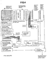
- FIG. 4 illustrates a schematic diagram showing the configuration of the median point calculating circuit in the two-dimensional neutron image detector using a scintillator and a wavelength shifting fiber.
- FIG. 5A and FIG. 5B show flow charts of the median point calculation in case that the generated fluorescent light incident into five wavelength shifting fibers for the vertical axis and the horizontal axis, respectively, upon the incidence of a neutron.
- the two-dimensional neutron image detector using a scintillator and a wavelength shifting fiber in this embodiment has the structure shown below.
- ZnS:Ag/ 10 B 2 O 3 scintillator having a thickness of 0.3mm is used as the neutron scintillator that emits the fluorescent light upon the incidence of a neutron.
- the wavelength of the fluorescent light emitted from ZnS:Ag has distributed from 390nm to 520nm at the center of 450nm.
- the life-time of the short life-time component of the fluorescent light from ZnS:Ag-based fluorescent material to be used for detecting neutrons substantially is about 0.3 ⁇ s.
- BCF-92MC commercially available from Saint-Gobain K.K., that is sensitive to the fluorescent light having the wavelength from 350nm to 440nm and transforms the wavelength of the fluorescent light into 490nm, is used as the wavelength shirting fiber.
- the shape of the wavelength shifting fiber is made in a right square having one side length of 0.5mm.
- a bundle of wavelength shifting fibers for fetching count values along the vertical axis is formed by arranging 64 wavelength shifting fibers in one-dimensional geometry.
- a bundle of wavelength shifting fibers for fetching count values along the horizontal axis is formed by arranging 64 wavelength shifting fibers in one-dimensional geometry on the bundle of wavelength shifting fibers for fetching count values along the vertical axis in one-dimensional geometry in the diagonal direction.
- ZnS:Ag/ 10 B 2 O 3 scintillator is formed above the bundle of those wavelength shifting fibers.
- a two-dimensional neutron detector having the dimension of the effective sensitive area of 32mm in height and 32mm in width may be formed.
- H7546 commercially available from HAMAMATSU PHOTONICS K.K. may be used, that is a 64-channnel photomultiplier tube for the horizontal axis and the vertical axis, respectively, each channel having an effective sensitive area of 2mm x 2mm.
- the individual photon electric signals output from the photomultiplier tubes for the horizontal axis and the vertical axis, respectively, are amplified by the photon signal amplifiers, each composed of a high-speed amplifier for the horizontal axis and the vertical axis, respectively, and then the individual amplified signals are formed as the photon digital pulse signals for the horizontal axis and the vertical axis, respectively, by the photon signal discriminating circuit composed of individual discriminator circuits.
- the photon signal amplifier and the photon signal discriminating circuit having an ability to detect the fluorescent lights using the photon counting method are used.
- the photon signal amplifier a couple of ICs, AD8001 commercially available from Analog Devices Inc. are used as high-speed ICs for the individual circuit and the overall amplifier is formed as an amplifier having a 60-times-amplifying gain with its amplifier bandwidth of 200MHz.
- AD8611 also commercially available from Analog Devices Inc. is used as the high-speed discriminator IC. Owing to applying the electronic circuit so configured as described above, the photon digital pulse signal having a pulse time width of about 5ns can be obtained as a single signal per photon.
- the photon digital pulse signal generated by the photon output from the individual photomultiplier tube is extracted as the signal synchronized to the clock signal having a cycle time adapted to its pulse time width by using the signal synchronization circuit composed of the gate circuit, and then the synchronized photon signal is obtained.
- the frequency of the clock signal is made 100MHz, generating the same pulse time width of 5ns because the pulse time width of the photon pulse signal is 5ns.
- the arithmetic "OR” operation is applied to the synchronized photon signals output for the vertical axis and the horizontal axis, respectively, each synchronized to one another, for all of 64 channels by "OR” circuit at first, and then, the timing when the pulse signal arrives at first to the input to "OR” circuit among the photon digital pulse signals obtained by detection and signal processing upon the incident of a neutron is defined to be the neutron incident time, and is made input to the count-time generating circuit .
- the count-time generating circuit supplies this first-arriving pulse signal as the start-time signal to the multi-channel photon digital counting circuit for the vertical axis and the horizontal axis, respectively, which start the counting operations at the individual channels.
- the circuit for observing the predetermined count out time in the count-time generating circuit starts at the same time, and then this circuit generates a stop signal upon the predetermined count time reached and sends the stop signal to the multi-channel photon digital counting circuits for the vertical axis and the horizontal axis, respectively, that terminate the counting operation and finally decides the counting values for the vertical axis and the horizontal axis, respectively.
- the count time is defined to be 1 ⁇ s corresponding to three times of 0.3 ⁇ s, that is the short life-time component of the fluorescent light from ZnS:Ag fluorescent material, so that almost all the short life-time component of the fluorescent light may be utilized.
- the photon count-value distribution at the center of the neutron incident position upon the single neutron incident into the scintillator is obtained in which the total amount of distributed photons is proportional to the amount of fluorescent light.
- the incident position in two-dimensional geometry is determined by calculating a median point on the basis of the obtained photon count-value distribution.
- the neutron incident position in two-dimensional geometry on the vertical axis and the horizontal axis, respectively is obtained individually by using the same method as described by referring to FIG. 3 in Embodiment 1.
- the position signals for the vertical axis and the horizontal axis, each obtained independently, are supplied to the coincidence counting circuit that judges whether the position signal for the vertical axis and the position signal for the horizontal axis establish coincidence by observing that those signals arrive during a predetermined time window.
- the coincidence count time (coincidence time) is defined to be 1 ⁇ s corresponding to three times of 0.3 ⁇ s, which is the short life-time component of the fluorescent light from ZnS:Ag fluorescent material.
- weight values for the photon count values at the individual positions are uniformly made equal to 1 in the above calculation example, though it is allowed that the uneven weight values may be used in order to increase the position accuracy in case that the detection characteristics for the fluorescent light is not uniform.
- neutron irradiation experiment was conducted by using cold neutrons having a wavelength of 4 A° at CHOP, Pulsed Neutron Instrument with Disk Chopper, at JRR-3 Research Reactor, Japan Atomic Energy Agency.
- a Cd(Cadmium)-based collimator plate having a hole having a diameter of 1.1 mm is placed in front of the neutron image detector of this embodiment, and the collimated neutron beam having a diameter of 1.1mm is made irradiated.
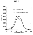
- FIG. 6 shows the comparison between the result obtained by applying the median point calculating method according to the present invention to the photon count distribution obtained by the neutron beam and the result obtained by applying the pattern matching method in the prior art to the same photon count distribution obtained as above. This figure is the result of viewing the two-dimensional incident position distribution in the horizontal-axis direction.
- the position resolution calculated by the pattern matching method in the prior art is 1.08mm while the position resolution calculated by the median point calculating method according to the present invention is 0.92mm, which proves that the position resolution can be improved by 0.16mm.
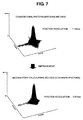
- the peak profile on the count-value distribution is observed to be shifted asymmetrically to the left side and the peak position is also shifted by the displacement corresponding to the gap between the adjacent wavelength shifting fibers, though the peak profile in the method according to the present invention is observed to be proximate to symmetrical Gaussian distribution, and its peak position is also observed to be located at the center of the distribution.
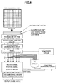
- FIG. 8 illustrates a schematic diagram showing the configuration of the median point calculating circuit in the two-dimensional neutron image detector for determining the incident position of the neutron by detecting the fluorescent light from the scintillator directly in two-dimensional geometry.
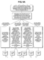
- FIG. 9A and FIG. 9B illustrates a flow chart of the median point calculation based on the basic principle of the median point calculation in two-dimensional geometry according to the present invention.
- the two-dimensional neutron image detector using a scintillator in this embodiment has the structure shown below.
- ZnS:Ag/ 10 B 2 O 3 scintillator having a thickness of 0.3mm is used as the neutron scintillator that emits the fluorescent light upon the incidence of a neutron.
- the wavelength of the fluorescent light emitted from ZnS:Ag has distributed from 390nm to 520nm at the center of 450nm.
- the life-time of the short life-time component of the fluorescent light from ZnS:Ag-based fluorescent material to be used for detecting neutrons substantially is about 0.3 ⁇ s.
- the photomultiplier tube that is a photoelectric detector sensitive to the light from the scintillator
- the photomultiplier measures a bunch of photons, which makes it difficult to obtain the designated accuracy in the photon count-value distribution, which will be described in detail in Embodiment 5.
- an optical plate used for attenuating the light intensity and also diffusing the light beam is provided in front of the photomultiplier tube.
- the light-intensity attenuation rate for the wavelength shifting fiber having a high detection efficiency as described in Embodiments 1 and 2 is 4%
- the light-intensity attenuation rate in this embodiment is made 1/25 so as to be the same level of light-intensity attenuation rate.
- this embodiment uses the fluorescent light emitted from the scintillator and attenuated by the optical plate used for attenuating the light intensity and also diffusing the light beam, it is allowed to using an optical guide method in which the fluorescent light may be attenuated by a few ten percents and detected by the photomultiplier tube.
- H7546 commercially available from HAMAMATSU PHOTONICS K.K. may be used, that is a 64-channnel photomultiplier tube, each channel having an effective sensitive area of 2mm x 2mm.
- the size of the neutron scintillator and the light-intensity attenuation filter is made to be 20mm x 20mm.
- the photon signal amplifier and the photon signal discriminating circuit having an ability to detect the fluorescent lights using the photon counting method are used.
- the photon signal amplifier a couple of ICs, AD8001 commercially available from Analog Devices Inc. are used as high-speed ICs for the individual circuit and the overall amplifier is formed as an amplifier having a 60-times-amplifying gain with its amplifier bandwidth of 200MHz.
- AD8611 also commercially available from Analog Devices Inc. is used as the high-speed discriminator IC. Owing to applying the electronic circuit so configured as described above, the photon digital pulse signal having a pulse time width of about 5ns can be obtained as a single signal per photon.
- the photon digital pulse signal generated by the photon output from the individual photomultiplier tube is extracted as the signal synchronized to the clock signal having a cycle time adapted to its pulse time width by using the signal synchronization circuit composed of the gate circuit, and then the synchronized photon signal is obtained.
- the frequency of the clock signal is made 100MHz, generating the same pulse time width of 5ns because the pulse time width of the photon pulse signal is 5ns.
- the arithmetic "OR” operation is applied to the synchronized photon signals output, each synchronized to one another, for all of 64 channels by "OR” circuit at first, and then, the timing when the pulse signal arrives at first to the input to "OR” circuit among the photon digital pulse signals obtained by detection and signal processing upon the incident of a neutron is defined to be the neutron incident time, and is made input to the count-time generating circuit.
- the count-time generating circuit supplies this first-arriving pulse signal as the start-time signal to the multi-channel photon digital counting circuit, which starts the counting operations at the individual channels.
- the circuit for observing the predetermined count out time in the count-time generating circuit starts at the same time, and then this circuit generates a stop signal upon the predetermined count time reached and sends the stop signal to the multi-channel photon digital counting circuit, that terminates the counting operation and finally decides the counting values.
- the count time is defined to be 1 ⁇ s corresponding to three times of 0.3 ⁇ s, that is the short life-time component of the fluorescent light from ZnS:Ag fluorescent material, so that almost all the short life-time component of the fluorescent light may be utilized.
- the photon count-value distribution at the center of the neutron incident position upon the single neutron incident into the scintillator can be obtained in which the total amount of distributed photons is proportional to the amount of fluorescent light, as shown in "Two-dimensional View” illustrated in two-dimensional geometry at the most upper part of FIG. 8
- the incident position in one-dimensional geometry is determined by calculating a median point on the basis of the obtained photon count-value distribution.
- One embodiment of the median point calculation is described by referring to the flow chart of the median point calculation using two-dimensional processing method shown in FIG. 9A and FIG. 9B .
- the position having the maximum count value is obtained at first.
- the position having the maximum count value is position 5 (five).
- the median point calculation is executed for the distinctive 4 (four) directions originated at the position 5 as the center, i.e. horizontal direction, diagonal direction 1, diagonal direction 2 and vertical direction.
- weight values for the photon count values at the individual positions are uniformly made equal to 1 in the above calculation example, though it is allowed that the uneven weight values may be used in order to increase the position accuracy in case that the detection characteristics for the fluorescent light is not uniform.
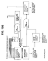
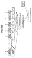
- FIG. 10A and FIG. 10B illustrate schematic diagrams showing the configuration of the median point calculating circuit in the two-dimensional neutron image detector using a scintillator and a wavelength shifting fiber according to the present invention.
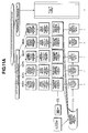
- FIG. 11A and FIG. 11B show flow charts of the median point calculation in case that the generated fluorescent light incident into five wavelength shifting fibers for the vertical axis and the horizontal axis, respectively, upon the incidence of a neutron.
- the two-dimensional neutron image detector using a scintillator and a wavelength shifting fiber in this embodiment has the same structure as Embodiment 2. Note that the additional function including the median-point calculating circuit and its down stream in the present invention will be now described.
- the neutron incident position in two-dimensional geometry on the vertical axis and the horizontal axis, respectively is determined individually by the median point calculation on the basis of the photon count-value distribution obtained by using the same method as Embodiment 2.
- the integrated value for the horizontal-axis count values and the an integrated value for the horizontal-axis count values, both obtained at median point calculation, are extracted for the signals to be used for discrimination, respectively.
- the position signals for the vertical axis and the horizontal axis are supplied to the coincidence counting circuit that judges whether the position signal for the vertical axis and the position signal for the horizontal axis establish coincidence by observing that those signals arrive during a predetermined time window. If their coincidence is proved to be valid, the neutron incident position signal is made output as the neutron signal, and if proved to be invalid, the neutron incident position signal is not made output.
- the coincidence count time (coincidence time) is defined to be 1 ⁇ s corresponding to three times of 0.3 ⁇ s, that is the life time of the short life-time component of the fluorescent light from ZnS:Ag fluorescent material.
- the present values for the position signals for the vertical axis and the horizontal axis, respectively are determined and then, the position signals are judged individually to be valid if the individual position signals are equal to or larger than the individual preset values.
- a single present discrimination value for the photon count value is used to be compared with the sum of the integrated value for the horizontal-axis count values and the integrated value for the vertical-axis count values in order to validate the position signal for the horizontal axis and the position signal for the vertical axis.
- neutron irradiation experiment was conducted by using cold neutrons having a wavelength of 4 A at CHOP, Pulsed Neutron Instrument with Disk Chopper, at JRR-3 Research Reactor, Japan Atomic Energy Agency.
- a Cd(Cadmium)-based collimator plate having a hole having a diameter of 1.1mm is placed in front of the neutron image detector of this embodiment, and the collimated neutron beam having a diameter of 1.1mm is made irradiated.
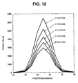
- FIG. 12 illustrates the measurement and signal processing result of the neutron beam measured by using the median point calculating method according to the present invention in case that the preset discrimination values for the photon count value for the integrated value for the horizontal-axis count values and the integrated value for the vertical-axis count values, respectively, are made identical to each other, and that the preset discrimination value is made change from 2 to 6.
- This figure is the result of viewing the two-dimensional incident position distribution in the horizontal-axis direction.
- This figure shows the changes of the peak profile in case that the preset discrimination values for the photon count value for the integrated value for the horizontal-axis count values and the integrated value for the vertical-axis count values, respectively, are made change from 2 to 6. It is proved that the peak profile does not change substantially even if the preset discrimination value for the photon count value changes, and that, as the preset discrimination value for the photon count value changes, the peak area decreases and the detection efficiency for the neutron decreases.
- FIG. 13 shows the analysis result of the position resolution for the peak profile for the preset discrimination value for the photon count value, the present discrimination value being changed from 2 to 7.
- the position resolution for the preset discrimination value for the photon count value being 6 is 0.81mm while the position resolution for the preset discrimination value being 2 is 1.04mm, which proves that the position resolution can be improved by 0.23mm.
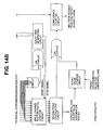
- FIG. 14A and FIG.14B illustrate schematic diagrams showing the configuration of the median point calculating circuit in the two-dimensional neutron image detector combining a semi-transparent scintillator manufactured by mixing ZnS:Ag fluorescent material, and 6 LiF or 10 B 2 O 3 as a neutron converter and a wavelength shifting fiber according to the present invention.
- FIG. 15A and FIG. 15B show flow charts of the median point calculation in case that the generated fluorescent light incident into five wavelength shifting fibers for the vertical axis and the horizontal axis, respectively, upon the incidence of a neutron.
- the two-dimensional neutron image detector using a scintillator and a wavelength shifting fiber in this embodiment has the same structure as Embodiment 2. Note that the additional function including the signal synchronization circuit and its down stream in the present invention will be now described.
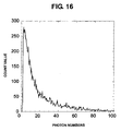
- FIG. 16 shows an example of the measurement result of the photon pulse-height distribution characteristics by detecting the fluorescent light from the neutron scintillator by the photomultiplier tube.
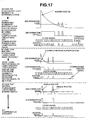
- FIG. 17 shows the nonlinearity in photon countings and its compensation method by classifying such photon superposition phenomena into three cases; extremely many photons generated, several photons generated, and photons generated intermittently.
- the discrimination output provides a single digital pulse having a long pulse width, and after that, several photon signals appear intermittently.
- the photon count number corresponding to the long pulse width of the digital pulse is obtained by using the signal synchronization circuit with the clock signals.
- the super-positioned photons can not be measured precisely.
- the exact number of photons implied by the super-positioned photon signal pulses is estimated by using the life-time of the fluorescent light.
- the exact number of photons can be also estimated by compensating the measured number of photons.
- the exact number of photons implied by the super-positioned photon signal pulses was estimated based on the relation between the relation between the discrimination levels in the photon signal discriminating circuit and the continuous pulse width of the digital pulse output from the photon signal discriminating circuit.
- a simple exponential function is used as the life-time decay curve.
- the discrimination level is so defined that the photon digital signal may accommodate the separately identifiable photon signal output from the amplifier with 90% fraction.
- FIG. 18 shows the relation between the exact number of incident photons to be estimated according to the above described conditions and the measured number of synchronized and output photons.
- the ideal relation between those entities is shown as the proportional line in FIG. 18 , the difference between the proportional line and the estimated curve is the number of photons to be used for compensation. For example, assuming that the exact number of incident photons is 60, the compensated number to the actually measured number of photons is 33, which is almost equal to the actually measured number, 27.
- some compensation and conversion formula or conversion table may be used for the median point calculation as shown in the flow chart of median point calculation in FIG. 15 at the linearity compensation circuit shown in FIG. 14 , and some false pulse may be generated corresponding to the input photon count numbers as shown in FIG. 17 illustrating an explanatory drawing for the principle of compensating the non-linearity.
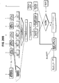
- FIG. 19 illustrates a schematic diagram showing the circuit configuration for removing the multiple countings due to after-glow (The life-time of the short life-time component of the fluorescent light is 70 ⁇ s) after the median point calculation with the time-delay circuit in the two-dimensional neutron image detector combining a semi-transparent scintillator manufactured by mixing ZnS:Ag fluorescent material, and 6 LiF or 10 B 2 O 3 as a neutron converter and a wavelength shifting fiber according to the present invention.
- FIG. 20A and FIG. 20B show flow charts of the process performed in the circuit configuration example when of the median point calculation in case that the generated fluorescent light incident into five wavelength shifting fibers for the vertical axis and the horizontal axis, respectively, upon the incidence of a neutron.
- the two-dimensional neutron image detector using a scintillator and a wavelength shifting fiber in this embodiment has the same structure as Embodiment 2. Note that the additional function including the median-point calculating circuit and its down stream in the present invention will be now described.
- a semi-transparent scintillator as a neutron scintillator manufactured by mixing ZnS:Ag fluorescent material, and 6 LiF or 10 B 2 O 3 as a neutron converter in the similar manner to Embodiment 5.
- the neutron detecting sheet commercially available from AST in England is used as the neutron scintillator, which is manufactured by using ZnS:Ag as fluorescent material, and mixing ZnS:Ag and 6 LiF with a mixing ratio of 4:1 by binder material.
- the thickness of the neutron scintillator is 0.45mm. Refer to FIG.
- the probability for the multiple countings can be obtained by actual measurement by changing the actual delay time to initiating the ready state of the processing circuit and by observing the multiple countings by using the actual neutron image detector.
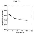
- FIG. 21 shows the relation between the delay time and the actual number of neutron countings as the raw data in the experimental result.
- the measurement condition assumes such a basic case that one or more photons enter the horizontal axis and one or more photons enters the vertical axis at the neutron image detector. It is observed that the neutron counting per 100 seconds is 8200 for the delay time of 2 ⁇ s though the neutron counting is 7000 for the enough delay time of 20 ⁇ s. It is proved that a fraction of multiple countings to the overall countings is 16% for the delay time of 2 ⁇ s.
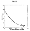
- FIG. 22 shows a fitting curve showing the relation between the fraction of multiple countings and the delay time on the basis of raw data described above. According to the figure, the fraction of multiple countings gets to as large as 16% in case of applying the delay time of 2 ⁇ s unconditionally. On the other hand, the fraction of multiple countings is as low as 1% in case of applying the delay time of 20 ⁇ s, which fails to establish neutron image detection with a higher counting rate because of the increased dead time.
- the delay time is so defined as to correspond to the optimal number of photon count value on the basis of the overall number of measured photons in the experiment.
- the delay time is so preset at the median point calculating circuit as to correspond to the sum of the integrated value for the vertical-axis photon count values and the integrated value for the horizontal-axis photon count values, and the initiation of the ready state for detecting the subsequent neutron incident is delayed by the delay time.
- the delay time to be preset is determined by analyzing the experimental result as described below.
- the relation between the delay time and the fraction of multiple countings to the overall countngs is required at first, which can be prepared by using the relational expression in FIG. 22 as described above.
- the relation between the overall photon countings and the multiple photon countings is obtained by normalizing the fraction of multiple countings so that the fraction of multiple countings may be 0.16 for 2 (two) photons, assuming that the fraction of multiple countings is proportional to a square of the number of photons and using the photon distribution in the ZnS-based scintillator as shown in FIG. 16 .
- the measurement condition assumes such a basic case that one or more photons enter the horizontal axis and one or more photons enters the vertical axis at the neutron image detector.
- FIG. 23 shows the relation between the obtained number of photons and the probability, that is, occurrence rate of multiple countings.
- FIG. 24 shows the computational result. It is proved that the delay time of 2 ⁇ s can be applied for the number of photons, 20 or smaller, and that the delay time should be increased linearly as the number of photon count number increases from 20 and more.
- this relational expression is implemented as the table or the relational expression into the delay-time preset circuit shown in FIG. 19 , such a neutron image detector can be realized so that the delay time may be adjusted in response to the measured number of photons on the basis of the flow chart shown in FIG. 20 .
- a two-dimensional neutron image detector having such a performance as being compliant to high-rate counting measurement can be obtained so that the counting loss may be as low as possible, the multiple countings due to the after-glow in the ZnS:Ag fluorescent material may be removed.
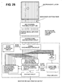
- FIG. 25 illustrates a schematic diagram showing the configuration of the median point calculating circuit in the one-dimensional neutron image detector using a scintillator and a wavelength shifting fiber.
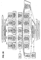
- FIG. 26 shows a flow chart of the median point calculation in case that the generated fluorescent light incident into five wavelength shifting fibers upon the incidence of a neutron.
- FIG. 27 shows a calculation example for the median point calculation based on the principle of mapping the synchronized photon signal to the position number value in calculating the median point without using the multiplication circuit.
- the one-dimensional neutron image detector using a scintillator and a wavelength shifting fiber in this embodiment has the same structure as Embodiment 1. Note that the additional function including the signal synchronization circuit and its down stream in the present invention will be now described.
- the integrated count value of photons for the individual position is obtained by adding operation to the number of photons at the individual position on the basis of the photon count value at the individual incident position stored at the multi-channel photon digital counting circuit.
- multiplication operation of the photon count value at the individual position and the corresponding position number value is performed and the resultant products are summed to obtain the photon median point count value summation.
- Those calculations require complicated circuits and computational times, and thus, it takes a longer time to determine the incident position on the basis of overall median point calculations, which fails to establish neutron image detection with a higher counting rate because of the increased dead time.
- the logical "OR” operation is applied to all the synchronized photon signals, each synchronized to one another, for all of 64 channels by "OR” circuit at first, and then, the timing when the pulse signal arrives at first to the input to "OR” circuit among the photon digital pulse signals obtained by detection and signal processing upon the incident of a neutron is defined to be the neutron incident time, and is made input to the count-time generating circuit.
- the count-time generating circuit supplies this first-arriving pulse signal as the start-time signal to the multi-channel photon digital counting circuit which starts the counting operations at the individual channels and summing operation for those count values, and also supplies this start-time signal to the position number value integrating circuit in order to start integrating operation for the position number values.
- All the synchronized photon signals are input to the multi-channel photon digital counting circuit, and resultantly the integrated count value of photons can be obtained.
- all he synchronized photon signals are input also to the photon synchronization signal-to position number converting circuit.
- the photon synchronization signal-to position number converting circuit generates the position number value corresponding to the individual incident position for the photon synchronization signal.
- the individual position number values generated above are input to the position number value integrating circuit, and resultantly the photon median point count value summation can be obtained.
- the circuit for observing the predetermined count out time in the count-time generating circuit starts at the same time, and then this circuit generates a stop signal upon the predetermined count time reached and sends the stop signal to the multi-channel photon digital counting circuit, that terminates the counting operation and finally decides the photon count integrated value and the photon median point count value summation.
- the count time is defined to be 1 ⁇ s corresponding to three times of 0.3 ⁇ s, that is the life time of the short life-time component of the fluorescent light from ZnS:Ag fluorescent material, so that almost all the short life-time component of the fluorescent light may be utilized.
- the neutron incident position can be obtained by dividing the obtained photon median point summation by the photon count integrated value by using a division circuit.
- the fluorescent lights enter 5 (five) wavelength shifting fibers at the fiber positions 3 to 5.
- the integrated count value A obtained by counting for the single neutron by using the wavelength shifting fibers is obtained by summing the count values at the positions 3 to 7, which makes 11 in this calculation example.
- the median point calculation summation B is obtained.
- the position number values from 3 to 7 are generated by the synchronized photon signals corresponding to the fiber positions 3 to 7, respectively.
- the individual generated position number values are made input to the position number value integrating circuit, in which the median point calculation summation B is obtained as 54 by summing its input values as shown in the figure.
- position 5 is obtained as the incident position by round-off calculation.
- a real value of 4.9 may be used as the coordinate value of the incident position.
- the incident position obtained in this embodiment is identical to the result obtained in the embodiment referring to FIG. 3 .
- FIG. 28 illustrates a schematic diagram showing the configuration of the median point calculating circuit in the two-dimensional neutron image detector combining a semi-transparent scintillator manufactured by mixing ZnS:Ag fluorescent material, and 6 LiF or 10 B 2 O 3 as a neutron converter and a wavelength shifting fiber according to the present invention.
- FIG. 15A and FIG. 15B illustrate a schematic diagram showing the configuration of the median point calculating circuit in the two-dimensional neutron image detector combining a semi-transparent scintillator manufactured by mixing ZnS:Ag fluorescent material, and 6 LiF or 10 B 2 O 3 as a neutron converter and a wavelength shifting fiber according to the present invention.
- 15B show flow charts of the median point calculation in case that, assuming a couple of neutrons incident simultaneously, in which one neutron having a higher intensity of the fluorescent light, that is, a larger integrated number of photons is defined as "Neutron 1" and the other neutron is defined as "neutron 2", the fluorescent light corresponding to Neutron 1 incident into five wavelength shifting fibers for the vertical axis and the horizontal axis, respectively, and the fluorescent light corresponding to Neutron 2 incident into three wavelength shifting fibers for the vertical axis and the horizontal axis, respectively, and then, those neutrons are discriminated.
- the two-dimensional neutron image detector using a scintillator and a wavelength shifting fiber in this embodiment has the same structure as Embodiment 2. Note that the additional function including the signal synchronization circuit and its down stream in the present invention will be now described.
- FIG. 16 shows an example of the measurement result of the photon pulse-height distribution characteristics by detecting the fluorescent light from the neutron scintillator by the photomultiplier tube.
- the number of generated photons upon the incident of a neutron is as many as 2 to 100.
- the count values for the vertical axis and the horizontal axis for the individual neutrons are compared with each other, respectively, a group of count values having relatively larger values and a group of count values having relatively smaller values are identified respectively to correspond to the individual neutrons in order to discriminate a couple of neutrons.
- the number of fibers detecting the photons generated by Neutron 1 in the horizontal axis and the vertical axis, respectively, is 5 (five)
- the number of fibers detecting the photons generated by Neutron 2 in the horizontal axis and the vertical axis, respectively, is 3 (three).
- the photon count-value distributions in the horizontal axis and the vertical axis respectively can be obtained by using the multi-channel photon digital counting circuit.
- a couple of neutron photon distributions associated with Neutron 1 and Neutron 2 are identified at the two distinctive positions in the photon count-value distribution in the horizontal axis.
- a couple of neutron photon distributions associated with Neutron 1 and Neutron 2 are identified at the two distinctive positions in the photon count-value distribution in the vertical axis.
- the count values for the two incident positions in the horizontal axis are summed by using the horizontal-axis two-neutron judgment circuit, and then, the whole sum NA of photons and the whole sum NB of photons are obtained, respectively.
- the whole sum NA of photons By comparing the whole sum NA of photons with the whole sum NB of photons, the larger one is identified to be the count-value distribution due to Neutron 1, and the smaller one is identified to be the count-value distribution due to Neutron 2.
- the neutron signal output is made NULL.
- the whole sum NA is larger than the whole sum NB, the whole sum NA is judged to be contributed by Neutron 1, and the whole sum NB is judged to be contributed by Neutron 2.
- the count values for the two incident positions in the vertical axis are summed by using the vertical-axis two-neutron judgment circuit, and then, the whole sum NC of photons and the whole sum ND of photons are obtained, respectively.
- the whole sum NC of photons By comparing the whole sum NC of photons with the whole sum ND of photons, the larger one is identified to be the count-value distribution due to Neutron 1, and the smaller one is identified to be the count-value distribution due to Neutron 2.
- the neutron signal output is made NULL.
- the whole sum ND is larger than the whole sum NC, the whole sum ND is judged to be contributed by Neutron 1, and the whole sum NC is judged to be contributed by Neutron 2.
- the coincidence measurement is performed by using the coincidence counting circuit. If their coincidence is verified to be valid, the neutron incident position signal (X1, Y1) is provided as Neutron 1 signal, and if their coincidence is verified to be invalid, then the neutron incident position signal is not provided.
- the coincidence count time (coincidence time) is defined to be 1 ⁇ s corresponding to three times of 0.3 ⁇ s, that is the life time of the short life-time component of the fluorescent light from ZnS:Ag fluorescent material.
- the coincidence measurement is performed by using the coincidence counting circuit. If their coincidence is verified to be valid, the neutron incident position signal (X2, Y2) is provided as Neutron 2 signal, and if their coincidence is verified to be invalid, then the neutron incident position signal is not provided.
- the coincidence count time (coincidence time) is defined to be 1 ⁇ s corresponding to three times of 0.3 ⁇ s, that is the life time of the short life-time component of the fluorescent light from ZnS:Ag fluorescent material.
- the first and third fibers are connected to photomultiplier tube 1, and the second fiber is connected to photomultiplier 2. Further, in an example of four fibers, the first and third fibers are connected to photomultiplier tube 1, and the second and fourth fibers are connected to photomultiplier 2. Even if five or more fibers are used, It is possible to construct a two-dimensional image detector in a similar manner.
Landscapes
- Physics & Mathematics (AREA)
- Health & Medical Sciences (AREA)
- Life Sciences & Earth Sciences (AREA)
- General Physics & Mathematics (AREA)
- High Energy & Nuclear Physics (AREA)
- Molecular Biology (AREA)
- Spectroscopy & Molecular Physics (AREA)
- Measurement Of Radiation (AREA)
Applications Claiming Priority (1)
| Application Number | Priority Date | Filing Date | Title |
|---|---|---|---|
| JP2010042209A JP5598905B2 (ja) | 2010-02-26 | 2010-02-26 | 中性子イメージ検出方法及びその方法を用いた中性子イメージ検出器 |
Publications (3)
| Publication Number | Publication Date |
|---|---|
| EP2386879A2 true EP2386879A2 (de) | 2011-11-16 |
| EP2386879A3 EP2386879A3 (de) | 2017-08-30 |
| EP2386879B1 EP2386879B1 (de) | 2021-05-05 |
Family
ID=44691536
Family Applications (1)
| Application Number | Title | Priority Date | Filing Date |
|---|---|---|---|
| EP11001589.8A Active EP2386879B1 (de) | 2010-02-26 | 2011-02-25 | Neutronenbilddetektionsverfahren und das Verfahren nutzender Neutronenbilddetektor |
Country Status (3)
| Country | Link |
|---|---|
| US (1) | US8253107B2 (de) |
| EP (1) | EP2386879B1 (de) |
| JP (1) | JP5598905B2 (de) |
Cited By (1)
| Publication number | Priority date | Publication date | Assignee | Title |
|---|---|---|---|---|
| FR3004272A1 (fr) * | 2013-04-09 | 2014-10-10 | Commissariat Energie Atomique | Dispositif de traitement de signaux detectes par des detecteurs de neutrons et dispositif de controle commande associe |
Families Citing this family (10)
| Publication number | Priority date | Publication date | Assignee | Title |
|---|---|---|---|---|
| JP6218224B2 (ja) | 2013-10-04 | 2017-10-25 | 国立研究開発法人日本原子力研究開発機構 | 中性子検出器 |
| JP6343785B2 (ja) * | 2014-03-18 | 2018-06-20 | 国立研究開発法人日本原子力研究開発機構 | 中性子シンチレータ |
| JP6452425B2 (ja) * | 2014-12-11 | 2019-01-16 | 株式会社日立製作所 | 放射線モニタ |
| JP2017053833A (ja) * | 2015-09-10 | 2017-03-16 | ソニー株式会社 | 補正装置、補正方法および測距装置 |
| JP6823526B2 (ja) * | 2017-04-14 | 2021-02-03 | 日立Geニュークリア・エナジー株式会社 | 放射線検出器および放射線の測定方法 |
| JP7062430B2 (ja) * | 2017-12-15 | 2022-05-06 | キヤノン株式会社 | 撮像素子、撮像装置および画像処理方法 |
| JP7299845B2 (ja) * | 2018-02-02 | 2023-06-28 | ソニーセミコンダクタソリューションズ株式会社 | 固体撮像素子、撮像装置、および、固体撮像素子の制御方法 |
| US11428831B2 (en) * | 2018-08-06 | 2022-08-30 | Lawrence Livermore National Security, Llc | Time-gated fast neutron transmission radiography system and method |
| JP7223993B2 (ja) * | 2019-02-27 | 2023-02-17 | 株式会社トプコン | 非破壊検査システム及び非破壊検査方法 |
| CN110244343B (zh) * | 2019-05-24 | 2024-08-02 | 广东太微加速器有限公司 | 一种中子束流的脉冲周期测试装置及测试方法 |
Citations (3)
| Publication number | Priority date | Publication date | Assignee | Title |
|---|---|---|---|---|
| JP2000187007A (ja) | 1998-12-24 | 2000-07-04 | Hitachi Cable Ltd | リードフレームの異常部の検出方法 |
| JP2002071816A (ja) | 2000-08-29 | 2002-03-12 | Japan Atom Energy Res Inst | 2次元放射線および中性子イメージ検出器 |
| JP2009008695A (ja) | 2008-10-14 | 2009-01-15 | Oval Corp | 振動方向規制手段を有するコリオリ流量計 |
Family Cites Families (9)
| Publication number | Priority date | Publication date | Assignee | Title |
|---|---|---|---|---|
| US3725657A (en) * | 1969-01-21 | 1973-04-03 | Nuclear Chicago Corp | Method and apparatus for determining efficiency in a liquid scintillation counting system |
| JP2000187077A (ja) | 1998-12-24 | 2000-07-04 | Japan Atom Energy Res Inst | 2次元放射線イメージ検出装置及びその検出方法 |
| US6590957B1 (en) * | 2002-03-13 | 2003-07-08 | William K. Warburton | Method and apparatus for producing spectra corrected for deadtime losses in spectroscopy systems operating under variable input rate conditions |
| JP2007107995A (ja) * | 2005-10-13 | 2007-04-26 | Toshiba Corp | 核医学イメージング装置及び画像データ生成方法 |
| JP4649583B2 (ja) * | 2006-06-27 | 2011-03-09 | 大学共同利用機関法人 高エネルギー加速器研究機構 | 中性子入射位置検出装置 |
| JP4791935B2 (ja) * | 2006-10-27 | 2011-10-12 | 独立行政法人日本原子力研究開発機構 | ZnS蛍光体を用いたシンチレーション中性子検出器の中性子/ガンマ線弁別方法 |
| US8015888B2 (en) | 2007-06-15 | 2011-09-13 | Hy-Energy, Llc | Thin-film sample holder |
| JP4635210B2 (ja) * | 2009-07-14 | 2011-02-23 | 独立行政法人 日本原子力研究開発機構 | 光ファイバを利用した放射線又は中性子の検出器 |
| US20110024634A1 (en) * | 2009-08-03 | 2011-02-03 | Radiation Monitoring Devices, Inc. | ENRICHED CsLiLn HALIDE SCINTILLATOR |
-
2010
- 2010-02-26 JP JP2010042209A patent/JP5598905B2/ja active Active
-
2011
- 2011-02-25 EP EP11001589.8A patent/EP2386879B1/de active Active
- 2011-02-25 US US13/035,248 patent/US8253107B2/en active Active
Patent Citations (3)
| Publication number | Priority date | Publication date | Assignee | Title |
|---|---|---|---|---|
| JP2000187007A (ja) | 1998-12-24 | 2000-07-04 | Hitachi Cable Ltd | リードフレームの異常部の検出方法 |
| JP2002071816A (ja) | 2000-08-29 | 2002-03-12 | Japan Atom Energy Res Inst | 2次元放射線および中性子イメージ検出器 |
| JP2009008695A (ja) | 2008-10-14 | 2009-01-15 | Oval Corp | 振動方向規制手段を有するコリオリ流量計 |
Non-Patent Citations (1)
| Title |
|---|
| NUCL. INSTR. AND METH., vol. A439, 1999, pages 311 - 320 |
Cited By (2)
| Publication number | Priority date | Publication date | Assignee | Title |
|---|---|---|---|---|
| FR3004272A1 (fr) * | 2013-04-09 | 2014-10-10 | Commissariat Energie Atomique | Dispositif de traitement de signaux detectes par des detecteurs de neutrons et dispositif de controle commande associe |
| WO2014166776A1 (fr) * | 2013-04-09 | 2014-10-16 | Commissariat à l'énergie atomique et aux énergies alternatives | Dispositif de traitement de signaux detectes par des detecteurs de neutrons et dispositif de controle commande associe |
Also Published As
| Publication number | Publication date |
|---|---|
| JP2011179863A (ja) | 2011-09-15 |
| US8253107B2 (en) | 2012-08-28 |
| EP2386879A3 (de) | 2017-08-30 |
| US20110284750A1 (en) | 2011-11-24 |
| JP5598905B2 (ja) | 2014-10-01 |
| EP2386879B1 (de) | 2021-05-05 |
Similar Documents
| Publication | Publication Date | Title |
|---|---|---|
| EP2386879B1 (de) | Neutronenbilddetektionsverfahren und das Verfahren nutzender Neutronenbilddetektor | |
| EP2533072B1 (de) | Detektor für zweidimensionale gepixelte bilder | |
| JP4791935B2 (ja) | ZnS蛍光体を用いたシンチレーション中性子検出器の中性子/ガンマ線弁別方法 | |
| KR101051126B1 (ko) | 플라스틱 섬광체 기반 방사선 검출기 및 이를 이용한 방사성 핵종 검출 방법 | |
| CN106547017A (zh) | 一种复合型闪烁体γ谱仪 | |
| JP6083637B2 (ja) | シンチレータを用いた中性子検出器及び中性子イメージ検出器 | |
| US7709801B2 (en) | Nuclear medicine diagnosis equipment | |
| JP2955487B2 (ja) | 放射線検出器および放射線検出方法 | |
| Du et al. | Continuous depth-of-interaction encoding using phosphor-coated scintillators | |
| JPWO2012093526A1 (ja) | 放射線検出器 | |
| CN113419270B (zh) | 一种在线式滤片堆栈谱仪 | |
| US8766206B2 (en) | Neutron detection based on energy spectrum characteristics | |
| JP5846960B2 (ja) | 放射線検出器 | |
| Ely et al. | Final technical report for the neutron detection without helium-3 project | |
| CN113126140B (zh) | 一种高速数字n/γ波形实时甄别的系统及方法 | |
| CN117518230B (zh) | 探测器、被动式中子源成像系统及方法 | |
| CN114509801B (zh) | 一种钆基材料的中子/伽马甄别系统及方法 | |
| Albrecht et al. | Performance of a cluster of multi-anode photomultipliers equipped with lenses for use in a prototype RICH detector | |
| TW201809722A (zh) | 計數方法以及放射線檢測裝置 | |
| JP4771265B2 (ja) | 放射線および中性子イメージ検出器 | |
| JP2004279184A (ja) | 放射線検出方法および装置 | |
| JP2020091241A (ja) | 中性子検出装置および中性子検出方法 | |
| Langeveld et al. | Implementation of Noise Spectroscopy using biased large-area photodiodes | |
| Zhao et al. | Single pixel readout of a MaPMT-based neutron anger camera system with waveform digitizers | |
| Antochi et al. | A GEM-based optically readout time projection chamber for charged particle tracking |
Legal Events
| Date | Code | Title | Description |
|---|---|---|---|
| 17P | Request for examination filed |
Effective date: 20110629 |
|
| AK | Designated contracting states |
Kind code of ref document: A2 Designated state(s): AL AT BE BG CH CY CZ DE DK EE ES FI FR GB GR HR HU IE IS IT LI LT LU LV MC MK MT NL NO PL PT RO RS SE SI SK SM TR |
|
| AX | Request for extension of the european patent |
Extension state: BA ME |
|
| PUAI | Public reference made under article 153(3) epc to a published international application that has entered the european phase |
Free format text: ORIGINAL CODE: 0009012 |
|
| PUAL | Search report despatched |
Free format text: ORIGINAL CODE: 0009013 |
|
| AK | Designated contracting states |
Kind code of ref document: A3 Designated state(s): AL AT BE BG CH CY CZ DE DK EE ES FI FR GB GR HR HU IE IS IT LI LT LU LV MC MK MT NL NO PL PT RO RS SE SI SK SM TR |
|
| AX | Request for extension of the european patent |
Extension state: BA ME |
|
| RIC1 | Information provided on ipc code assigned before grant |
Ipc: G01T 3/06 20060101AFI20170726BHEP |
|
| STAA | Information on the status of an ep patent application or granted ep patent |
Free format text: STATUS: EXAMINATION IS IN PROGRESS |
|
| 17Q | First examination report despatched |
Effective date: 20190415 |
|
| GRAP | Despatch of communication of intention to grant a patent |
Free format text: ORIGINAL CODE: EPIDOSNIGR1 |
|
| STAA | Information on the status of an ep patent application or granted ep patent |
Free format text: STATUS: GRANT OF PATENT IS INTENDED |
|
| INTG | Intention to grant announced |
Effective date: 20201007 |
|
| RIN1 | Information on inventor provided before grant (corrected) |
Inventor name: YORIBAYASHI, YUTAKA Inventor name: EBINE, MASUMI Inventor name: NAKAMURA, TATSUYA Inventor name: KATAGIRI, MASAKI Inventor name: BIRUMACHI, ATSUSHI |
|
| GRAJ | Information related to disapproval of communication of intention to grant by the applicant or resumption of examination proceedings by the epo deleted |
Free format text: ORIGINAL CODE: EPIDOSDIGR1 |
|
| STAA | Information on the status of an ep patent application or granted ep patent |
Free format text: STATUS: EXAMINATION IS IN PROGRESS |
|
| GRAS | Grant fee paid |
Free format text: ORIGINAL CODE: EPIDOSNIGR3 |
|
| STAA | Information on the status of an ep patent application or granted ep patent |
Free format text: STATUS: GRANT OF PATENT IS INTENDED |
|
| GRAP | Despatch of communication of intention to grant a patent |
Free format text: ORIGINAL CODE: EPIDOSNIGR1 |
|
| INTC | Intention to grant announced (deleted) | ||
| GRAA | (expected) grant |
Free format text: ORIGINAL CODE: 0009210 |
|
| STAA | Information on the status of an ep patent application or granted ep patent |
Free format text: STATUS: THE PATENT HAS BEEN GRANTED |
|
| INTG | Intention to grant announced |
Effective date: 20210312 |
|
| RAP3 | Party data changed (applicant data changed or rights of an application transferred) |
Owner name: JAPAN ATOMIC ENERGY AGENCY Owner name: HOSHIN ELECTRONICS CO., LTD. |
|
| AK | Designated contracting states |
Kind code of ref document: B1 Designated state(s): AL AT BE BG CH CY CZ DE DK EE ES FI FR GB GR HR HU IE IS IT LI LT LU LV MC MK MT NL NO PL PT RO RS SE SI SK SM TR |
|
| REG | Reference to a national code |
Ref country code: GB Ref legal event code: FG4D |
|
| REG | Reference to a national code |
Ref country code: CH Ref legal event code: EP |
|
| REG | Reference to a national code |
Ref country code: AT Ref legal event code: REF Ref document number: 1390502 Country of ref document: AT Kind code of ref document: T Effective date: 20210515 |
|
| REG | Reference to a national code |
Ref country code: IE Ref legal event code: FG4D |
|
| REG | Reference to a national code |
Ref country code: DE Ref legal event code: R096 Ref document number: 602011070860 Country of ref document: DE |
|
| REG | Reference to a national code |
Ref country code: SE Ref legal event code: TRGR |
|
| REG | Reference to a national code |
Ref country code: LT Ref legal event code: MG9D |
|
| REG | Reference to a national code |
Ref country code: AT Ref legal event code: MK05 Ref document number: 1390502 Country of ref document: AT Kind code of ref document: T Effective date: 20210505 |
|
| PG25 | Lapsed in a contracting state [announced via postgrant information from national office to epo] |
Ref country code: FI Free format text: LAPSE BECAUSE OF FAILURE TO SUBMIT A TRANSLATION OF THE DESCRIPTION OR TO PAY THE FEE WITHIN THE PRESCRIBED TIME-LIMIT Effective date: 20210505 Ref country code: LT Free format text: LAPSE BECAUSE OF FAILURE TO SUBMIT A TRANSLATION OF THE DESCRIPTION OR TO PAY THE FEE WITHIN THE PRESCRIBED TIME-LIMIT Effective date: 20210505 Ref country code: AT Free format text: LAPSE BECAUSE OF FAILURE TO SUBMIT A TRANSLATION OF THE DESCRIPTION OR TO PAY THE FEE WITHIN THE PRESCRIBED TIME-LIMIT Effective date: 20210505 Ref country code: BG Free format text: LAPSE BECAUSE OF FAILURE TO SUBMIT A TRANSLATION OF THE DESCRIPTION OR TO PAY THE FEE WITHIN THE PRESCRIBED TIME-LIMIT Effective date: 20210805 Ref country code: HR Free format text: LAPSE BECAUSE OF FAILURE TO SUBMIT A TRANSLATION OF THE DESCRIPTION OR TO PAY THE FEE WITHIN THE PRESCRIBED TIME-LIMIT Effective date: 20210505 |
|
| PG25 | Lapsed in a contracting state [announced via postgrant information from national office to epo] |
Ref country code: LV Free format text: LAPSE BECAUSE OF FAILURE TO SUBMIT A TRANSLATION OF THE DESCRIPTION OR TO PAY THE FEE WITHIN THE PRESCRIBED TIME-LIMIT Effective date: 20210505 Ref country code: IS Free format text: LAPSE BECAUSE OF FAILURE TO SUBMIT A TRANSLATION OF THE DESCRIPTION OR TO PAY THE FEE WITHIN THE PRESCRIBED TIME-LIMIT Effective date: 20210905 Ref country code: GR Free format text: LAPSE BECAUSE OF FAILURE TO SUBMIT A TRANSLATION OF THE DESCRIPTION OR TO PAY THE FEE WITHIN THE PRESCRIBED TIME-LIMIT Effective date: 20210806 Ref country code: RS Free format text: LAPSE BECAUSE OF FAILURE TO SUBMIT A TRANSLATION OF THE DESCRIPTION OR TO PAY THE FEE WITHIN THE PRESCRIBED TIME-LIMIT Effective date: 20210505 Ref country code: PT Free format text: LAPSE BECAUSE OF FAILURE TO SUBMIT A TRANSLATION OF THE DESCRIPTION OR TO PAY THE FEE WITHIN THE PRESCRIBED TIME-LIMIT Effective date: 20210906 Ref country code: PL Free format text: LAPSE BECAUSE OF FAILURE TO SUBMIT A TRANSLATION OF THE DESCRIPTION OR TO PAY THE FEE WITHIN THE PRESCRIBED TIME-LIMIT Effective date: 20210505 Ref country code: NO Free format text: LAPSE BECAUSE OF FAILURE TO SUBMIT A TRANSLATION OF THE DESCRIPTION OR TO PAY THE FEE WITHIN THE PRESCRIBED TIME-LIMIT Effective date: 20210805 Ref country code: ES Free format text: LAPSE BECAUSE OF FAILURE TO SUBMIT A TRANSLATION OF THE DESCRIPTION OR TO PAY THE FEE WITHIN THE PRESCRIBED TIME-LIMIT Effective date: 20210505 |
|
| REG | Reference to a national code |
Ref country code: NL Ref legal event code: MP Effective date: 20210505 |
|
| PG25 | Lapsed in a contracting state [announced via postgrant information from national office to epo] |
Ref country code: NL Free format text: LAPSE BECAUSE OF FAILURE TO SUBMIT A TRANSLATION OF THE DESCRIPTION OR TO PAY THE FEE WITHIN THE PRESCRIBED TIME-LIMIT Effective date: 20210505 |
|
| PG25 | Lapsed in a contracting state [announced via postgrant information from national office to epo] |
Ref country code: RO Free format text: LAPSE BECAUSE OF FAILURE TO SUBMIT A TRANSLATION OF THE DESCRIPTION OR TO PAY THE FEE WITHIN THE PRESCRIBED TIME-LIMIT Effective date: 20210505 Ref country code: SK Free format text: LAPSE BECAUSE OF FAILURE TO SUBMIT A TRANSLATION OF THE DESCRIPTION OR TO PAY THE FEE WITHIN THE PRESCRIBED TIME-LIMIT Effective date: 20210505 Ref country code: SM Free format text: LAPSE BECAUSE OF FAILURE TO SUBMIT A TRANSLATION OF THE DESCRIPTION OR TO PAY THE FEE WITHIN THE PRESCRIBED TIME-LIMIT Effective date: 20210505 Ref country code: DK Free format text: LAPSE BECAUSE OF FAILURE TO SUBMIT A TRANSLATION OF THE DESCRIPTION OR TO PAY THE FEE WITHIN THE PRESCRIBED TIME-LIMIT Effective date: 20210505 Ref country code: EE Free format text: LAPSE BECAUSE OF FAILURE TO SUBMIT A TRANSLATION OF THE DESCRIPTION OR TO PAY THE FEE WITHIN THE PRESCRIBED TIME-LIMIT Effective date: 20210505 Ref country code: CZ Free format text: LAPSE BECAUSE OF FAILURE TO SUBMIT A TRANSLATION OF THE DESCRIPTION OR TO PAY THE FEE WITHIN THE PRESCRIBED TIME-LIMIT Effective date: 20210505 |
|
| REG | Reference to a national code |
Ref country code: DE Ref legal event code: R097 Ref document number: 602011070860 Country of ref document: DE |
|
| PLBE | No opposition filed within time limit |
Free format text: ORIGINAL CODE: 0009261 |
|
| STAA | Information on the status of an ep patent application or granted ep patent |
Free format text: STATUS: NO OPPOSITION FILED WITHIN TIME LIMIT |
|
| 26N | No opposition filed |
Effective date: 20220208 |
|
| PG25 | Lapsed in a contracting state [announced via postgrant information from national office to epo] |
Ref country code: IS Free format text: LAPSE BECAUSE OF FAILURE TO SUBMIT A TRANSLATION OF THE DESCRIPTION OR TO PAY THE FEE WITHIN THE PRESCRIBED TIME-LIMIT Effective date: 20210905 Ref country code: AL Free format text: LAPSE BECAUSE OF FAILURE TO SUBMIT A TRANSLATION OF THE DESCRIPTION OR TO PAY THE FEE WITHIN THE PRESCRIBED TIME-LIMIT Effective date: 20210505 |
|
| PG25 | Lapsed in a contracting state [announced via postgrant information from national office to epo] |
Ref country code: IT Free format text: LAPSE BECAUSE OF FAILURE TO SUBMIT A TRANSLATION OF THE DESCRIPTION OR TO PAY THE FEE WITHIN THE PRESCRIBED TIME-LIMIT Effective date: 20210505 |
|
| REG | Reference to a national code |
Ref country code: DE Ref legal event code: R119 Ref document number: 602011070860 Country of ref document: DE |
|
| PG25 | Lapsed in a contracting state [announced via postgrant information from national office to epo] |
Ref country code: MC Free format text: LAPSE BECAUSE OF FAILURE TO SUBMIT A TRANSLATION OF THE DESCRIPTION OR TO PAY THE FEE WITHIN THE PRESCRIBED TIME-LIMIT Effective date: 20210505 |
|
| REG | Reference to a national code |
Ref country code: CH Ref legal event code: PL |
|
| REG | Reference to a national code |
Ref country code: BE Ref legal event code: MM Effective date: 20220228 |
|
| PG25 | Lapsed in a contracting state [announced via postgrant information from national office to epo] |
Ref country code: LU Free format text: LAPSE BECAUSE OF NON-PAYMENT OF DUE FEES Effective date: 20220225 |
|
| PG25 | Lapsed in a contracting state [announced via postgrant information from national office to epo] |
Ref country code: FR Free format text: LAPSE BECAUSE OF NON-PAYMENT OF DUE FEES Effective date: 20220228 |
|
| PG25 | Lapsed in a contracting state [announced via postgrant information from national office to epo] |
Ref country code: LI Free format text: LAPSE BECAUSE OF NON-PAYMENT OF DUE FEES Effective date: 20220228 Ref country code: IE Free format text: LAPSE BECAUSE OF NON-PAYMENT OF DUE FEES Effective date: 20220225 Ref country code: DE Free format text: LAPSE BECAUSE OF NON-PAYMENT OF DUE FEES Effective date: 20220901 Ref country code: CH Free format text: LAPSE BECAUSE OF NON-PAYMENT OF DUE FEES Effective date: 20220228 |
|
| PG25 | Lapsed in a contracting state [announced via postgrant information from national office to epo] |
Ref country code: BE Free format text: LAPSE BECAUSE OF NON-PAYMENT OF DUE FEES Effective date: 20220228 |
|
| PG25 | Lapsed in a contracting state [announced via postgrant information from national office to epo] |
Ref country code: HU Free format text: LAPSE BECAUSE OF FAILURE TO SUBMIT A TRANSLATION OF THE DESCRIPTION OR TO PAY THE FEE WITHIN THE PRESCRIBED TIME-LIMIT; INVALID AB INITIO Effective date: 20110225 |
|
| PG25 | Lapsed in a contracting state [announced via postgrant information from national office to epo] |
Ref country code: MK Free format text: LAPSE BECAUSE OF FAILURE TO SUBMIT A TRANSLATION OF THE DESCRIPTION OR TO PAY THE FEE WITHIN THE PRESCRIBED TIME-LIMIT Effective date: 20210505 Ref country code: CY Free format text: LAPSE BECAUSE OF FAILURE TO SUBMIT A TRANSLATION OF THE DESCRIPTION OR TO PAY THE FEE WITHIN THE PRESCRIBED TIME-LIMIT Effective date: 20210505 |
|
| PG25 | Lapsed in a contracting state [announced via postgrant information from national office to epo] |
Ref country code: MT Free format text: LAPSE BECAUSE OF FAILURE TO SUBMIT A TRANSLATION OF THE DESCRIPTION OR TO PAY THE FEE WITHIN THE PRESCRIBED TIME-LIMIT Effective date: 20210505 |
|
| PG25 | Lapsed in a contracting state [announced via postgrant information from national office to epo] |
Ref country code: TR Free format text: LAPSE BECAUSE OF FAILURE TO SUBMIT A TRANSLATION OF THE DESCRIPTION OR TO PAY THE FEE WITHIN THE PRESCRIBED TIME-LIMIT Effective date: 20210505 |
|
| PGFP | Annual fee paid to national office [announced via postgrant information from national office to epo] |
Ref country code: SE Payment date: 20260223 Year of fee payment: 16 |
|
| PGFP | Annual fee paid to national office [announced via postgrant information from national office to epo] |
Ref country code: GB Payment date: 20260223 Year of fee payment: 16 |