EP2386887A1 - Système d'ensemble de collimateur à fibres optiques et procédé de fabrication du système d'ensemble de collimateur à fibres optiques - Google Patents
Système d'ensemble de collimateur à fibres optiques et procédé de fabrication du système d'ensemble de collimateur à fibres optiques Download PDFInfo
- Publication number
- EP2386887A1 EP2386887A1 EP11177327A EP11177327A EP2386887A1 EP 2386887 A1 EP2386887 A1 EP 2386887A1 EP 11177327 A EP11177327 A EP 11177327A EP 11177327 A EP11177327 A EP 11177327A EP 2386887 A1 EP2386887 A1 EP 2386887A1
- Authority
- EP
- European Patent Office
- Prior art keywords
- grin lens
- optical fiber
- fiber optic
- optical
- grin
- Prior art date
- Legal status (The legal status is an assumption and is not a legal conclusion. Google has not performed a legal analysis and makes no representation as to the accuracy of the status listed.)
- Granted
Links
Images






Classifications
-
- G—PHYSICS
- G02—OPTICS
- G02B—OPTICAL ELEMENTS, SYSTEMS OR APPARATUS
- G02B6/00—Light guides; Structural details of arrangements comprising light guides and other optical elements, e.g. couplings
- G02B6/24—Coupling light guides
- G02B6/26—Optical coupling means
- G02B6/32—Optical coupling means having lens focusing means positioned between opposed fibre ends
-
- G—PHYSICS
- G02—OPTICS
- G02B—OPTICAL ELEMENTS, SYSTEMS OR APPARATUS
- G02B23/00—Telescopes, e.g. binoculars; Periscopes; Instruments for viewing the inside of hollow bodies; Viewfinders; Optical aiming or sighting devices
- G02B23/02—Telescopes, e.g. binoculars; Periscopes; Instruments for viewing the inside of hollow bodies; Viewfinders; Optical aiming or sighting devices involving prisms or mirrors
- G02B23/10—Telescopes, e.g. binoculars; Periscopes; Instruments for viewing the inside of hollow bodies; Viewfinders; Optical aiming or sighting devices involving prisms or mirrors reflecting into the field of view additional indications, e.g. from collimator
-
- G—PHYSICS
- G02—OPTICS
- G02B—OPTICAL ELEMENTS, SYSTEMS OR APPARATUS
- G02B6/00—Light guides; Structural details of arrangements comprising light guides and other optical elements, e.g. couplings
- G02B6/24—Coupling light guides
- G02B6/255—Splicing of light guides, e.g. by fusion or bonding
- G02B6/2551—Splicing of light guides, e.g. by fusion or bonding using thermal methods, e.g. fusion welding by arc discharge, laser beam, plasma torch
-
- G—PHYSICS
- G02—OPTICS
- G02B—OPTICAL ELEMENTS, SYSTEMS OR APPARATUS
- G02B6/00—Light guides; Structural details of arrangements comprising light guides and other optical elements, e.g. couplings
- G02B6/24—Coupling light guides
- G02B6/26—Optical coupling means
- G02B6/27—Optical coupling means with polarisation selective and adjusting means
- G02B6/2746—Optical coupling means with polarisation selective and adjusting means comprising non-reciprocal devices, e.g. isolators, FRM, circulators, quasi-isolators
-
- G—PHYSICS
- G02—OPTICS
- G02B—OPTICAL ELEMENTS, SYSTEMS OR APPARATUS
- G02B6/00—Light guides; Structural details of arrangements comprising light guides and other optical elements, e.g. couplings
- G02B6/24—Coupling light guides
- G02B6/26—Optical coupling means
- G02B6/28—Optical coupling means having data bus means, i.e. plural waveguides interconnected and providing an inherently bidirectional system by mixing and splitting signals
- G02B6/293—Optical coupling means having data bus means, i.e. plural waveguides interconnected and providing an inherently bidirectional system by mixing and splitting signals with wavelength selective means
- G02B6/29346—Optical coupling means having data bus means, i.e. plural waveguides interconnected and providing an inherently bidirectional system by mixing and splitting signals with wavelength selective means operating by wave or beam interference
- G02B6/29361—Interference filters, e.g. multilayer coatings, thin film filters, dichroic splitters or mirrors based on multilayers, WDM filters
- G02B6/2937—In line lens-filtering-lens devices, i.e. elements arranged along a line and mountable in a cylindrical package for compactness, e.g. 3- port device with GRIN lenses sandwiching a single filter operating at normal incidence in a tubular package
-
- G—PHYSICS
- G02—OPTICS
- G02B—OPTICAL ELEMENTS, SYSTEMS OR APPARATUS
- G02B6/00—Light guides; Structural details of arrangements comprising light guides and other optical elements, e.g. couplings
- G02B6/24—Coupling light guides
- G02B6/26—Optical coupling means
- G02B6/35—Optical coupling means having switching means
- G02B6/351—Optical coupling means having switching means involving stationary waveguides with moving interposed optical elements
- G02B6/3512—Optical coupling means having switching means involving stationary waveguides with moving interposed optical elements the optical element being reflective, e.g. mirror
-
- G—PHYSICS
- G02—OPTICS
- G02B—OPTICAL ELEMENTS, SYSTEMS OR APPARATUS
- G02B6/00—Light guides; Structural details of arrangements comprising light guides and other optical elements, e.g. couplings
- G02B6/24—Coupling light guides
- G02B6/26—Optical coupling means
- G02B6/35—Optical coupling means having switching means
- G02B6/354—Switching arrangements, i.e. number of input/output ports and interconnection types
- G02B6/3554—3D constellations, i.e. with switching elements and switched beams located in a volume
- G02B6/3556—NxM switch, i.e. regular arrays of switches elements of matrix type constellation
-
- G—PHYSICS
- G02—OPTICS
- G02B—OPTICAL ELEMENTS, SYSTEMS OR APPARATUS
- G02B6/00—Light guides; Structural details of arrangements comprising light guides and other optical elements, e.g. couplings
- G02B6/24—Coupling light guides
- G02B6/36—Mechanical coupling means
- G02B6/3628—Mechanical coupling means for mounting fibres to supporting carriers
- G02B6/3648—Supporting carriers of a microbench type, i.e. with micromachined additional mechanical structures
- G02B6/3652—Supporting carriers of a microbench type, i.e. with micromachined additional mechanical structures the additional structures being prepositioning mounting areas, allowing only movement in one dimension, e.g. grooves, trenches or vias in the microbench surface, i.e. self aligning supporting carriers
-
- G—PHYSICS
- G02—OPTICS
- G02B—OPTICAL ELEMENTS, SYSTEMS OR APPARATUS
- G02B6/00—Light guides; Structural details of arrangements comprising light guides and other optical elements, e.g. couplings
- G02B6/24—Coupling light guides
- G02B6/36—Mechanical coupling means
- G02B6/3628—Mechanical coupling means for mounting fibres to supporting carriers
- G02B6/3664—2D cross sectional arrangements of the fibres
- G02B6/3676—Stacked arrangement
Definitions
- the present invention relates to a fiber optic collimator system that disposes optical fibers with GRIN lenses being opposingly arranged and holding arbitrary optical elements, a fiber optic collimator array comprising a plurality of optical fibers with GRIN lenses being positioned in parallel, a method of manufacturing the fiber optic collimator system, and a method of manufacturing the fiber optic collimator array system that disposes the fiber optic collimator arrays in an opposed arrangement.
- an outgoing light which is a light emerged from one optical fiber is converted to a parallel light by a collimator lens.
- the parallel light after propagation is collected by another collimator lens, and is input to another optical fiber.
- Such an optical system is called a "collimator system” whereby a diverse optical module can be constructed by inserting various optical elements such as a filter, an optical isolator element, an optical switch, an optical modulator, or the like, between the collimator lenses.
- a convex lens is typically used as the collimator lens.
- GRIN lens cylindrical graded index lens
- the GRIN lens when a refractive index n of the GRIN lens, as viewed from its cross-sectional direction x, y, is defined in the following equation (1), the GRIN lens shows the maximum refractive index at a cylindrical core axis. The refractive index decreases continuously in a second degree curve as being directed away from the core toward the peripheral direction. A lens effect is carried out according to this refractive index distribution.
- n n 0 1 - g 2 ⁇ r 2 / 2
- reference character g denotes a constant showing a light-collecting ability of the GRIN lens
- no denotes a refractive index of a material of the GRIN lens
- NA numerical aperture
- a length (L) of the GRIN lens used as the collimator lens is set to a quarter length of the meander cycle of propagation light that propagates inside the GRIN lens, or set to its odd multiple.
- L 1/4 is the quarter meander cycle of propagation light that propagates inside the GRIN lens
- Fig. 2 is a perspective view showing a single core collimator system having a pair of the GRIN lens 1a and 1b, which are opposingly arranged.
- the optical fibers 2a and 2b are connected to the GRIN lenses 1a and 1b at the end faces opposite to the facing planes by making the optical axes coincide.
- An optical signal transmission is carried out by outputting a light from one of the optical fiber 2a to the GRIN lens 1a connected thereto as a parallel light, collecting the parallel light at the other GRIN lens 1b, and introducing the light into the optical fiber 2b connected thereto.
- the optical axes of the opposing GRIN lenses 1a and 1b must precisely coincide, as well as the optical axes of the GRIN lenses 1a and 1b and the optical axes of the optical fibers 2a and 2b, to reduce the coupling loss.
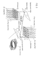
- Fig. 3 is a schematic perspective and explanatory view showing the fiber optic collimator array system in which a pair of the optical fiber collimator arrays 1 are opposingly arranged.
- two-staged MEMS-type (micro electro-mechanical systems) optical switch arrays 3 having 2 degrees of freedom are inserted.
- the optical fibers 2a and 2b are connected by making the optical axes coincide so as to construct the optical fiber arrays 2 which are a group of these optical fibers.
- An optical signal transmission is carried out by outputting a light from each optical fiber 2a at one end, which is converted to a parallel light at the GRIN lens 1a connected thereto, reflecting two times at the optical switches 3a and 3b of the optical switch arrays 3, changing a direction of the parallel light by changing a reflection angle, collecting the parallel light at each GRIN lens 1b at the other end, and introducing it into the optical fiber 2b connected thereto.
- An optical path of the light is switched by appropriately changing the reflection angles of micro-mirrors 3c having 2 degrees of freedom comprised of two-staged MEMS-type optical switch arrays 3.
- the optical axes of the opposing GRIN lenses 1a and 1b must precisely coincide respectively, as well as the optical axes of each of the GRIN lenses 1a and each of the optical fibers 2a, to reduce the coupling loss.
- Fig. 4 shows an actual example of a single core collimator system loading the optical isolator element.
- the industry-wide standard for an optical fiber core wire 7 is 0.9mm.
- This optical fiber core wire 7 with built-in GRIN lens 1a and optical fiber 2a of 1.8 mm is inserted, adhered, and fixed to both ends of the optical fiber lens holder (metal) 8 of a concentric circle which is controlled to an outer dimension of 3 mm and inner diameters of 1.8 mm and 0.9 mm.
- the core wire 7 is made by covering the optical fibers 2a and 2b with a plastic and the like.
- the optical fiber lens holder 8 is inserted into a collimator holder (metal) 9 controlled to the outer dimension of 10 mm and the inner diameter of 3 mm, and fixed to the collimator holder 9 by a fixing flange 11. Because the optical axis alignment of the single core collimator system facing each other accordingly is influenced by the processing precision of the inner diameter of the collimator holder 9 and the outer dimension and inner diameters of the optical fiber lens holder 8, a high level of processing precision is demanded.
- the light that is output from the optical fiber 2a is collected at the GRIN lens 1a, which is output as approximately a parallel light 6.
- the substantially parallel light 6 is collected at the GRIN lens 1b at another end, and input to the optical fiber 2b.
- the collimator system functions accordingly.
- Various optical elements 10, such as an optical isolator component of the present example, are included and fixed between the opposing pair of collimator systems.
- the Z direction is defined as a direction parallel to the optical axis C
- the X direction is defined as a direction perpendicular to the horizontal direction
- the Y direction is defined as a direction perpendicular to the vertical direction, as the possible axis displacements between the facing lens, there occurs a displacement in the X direction, an inclination angle in the X direction ⁇ x, a displacement in the Y direction, and an inclination angle in the Y direction ⁇ y.
- Fig. 3 in the case of the fiber optic collimator array system in which two-staged MEMS-type (micro electro-mechanical systems) optical switch arrays 3 having 2 degrees of freedom are inserted between the two fiber optic collimator arrays 1 and 1, an optical path of the light can be switched by appropriately changing the reflection angles of the micro-mirrors 3c having 2 degrees of freedom comprised of the two-staged MEMS-type optical switch arrays 3.
- the mirror angles of each of the micro-mirrors 3c inside the optical switch array are not all equal and will vary slightly.
- the MEMS-type optical fiber collimator array system typically generates a large axial displacement in comparison to the single core collimator system in which the pair of GRIN lens 1a and 1b, shown in Fig. 2 , are ordinarily arranged so as to oppose each other.
- a GRIN lens and an optical fiber are connected by using an adhesive.
- Adhesives such as that disclosed in U.S. Patent No. 4,213,677 are used to fix the optical fiber and the GRIN lens.
- the optical adhesive has an absorption ranging from 1 to 5%, and an alteration temperature of about 400°C at maximum. The adhesive fails to tolerate the light intensity of a several Watts class for the physical property of this range.
- the GI optical fiber is an optical fiber with a radially varying refractive index at the core.
- the GI optical fiber is made of quartz, which is the same as the material forming the optical fiber, which allows it to be fused and spliced to the optical fiber, and the tolerance against the highly intensive light is expected to be obtained.
- the normal GI optical fiber is formed by a chemical vapor deposition method.
- NA 0.38
- an amount of additives such as GeO 2 , P 2 O 5
- this GI optical fiber is practically poor in handling upon fabricating the collimator lens in terms of matching the thermal expansion property, such that the parent material is liable to crack by an increase of the thermal expansion coefficient, and in terms of controllability of the refractive index, such as being unable to obtain the higher NA.
- the present invention was accomplished in consideration of such circumstances, and has as its object to provide a fiber optic collimator system and a fiber optic collimator array system that can reduce the difficulty in the core alignment processing, minimize the coupling loss, and prevent the optical characteristics from deteriorating.
- the present invention also has as its object to provide a method for efficiently producing the fiber optic collimator system and the fiber optic collimator array system that can minimize the coupling loss.
- the present invention is a fiber optic collimator system which is characterized in that an optical fiber is fused to one end of the GRIN lens (Graded Index Lens) made of quartz glass containing one or more selected from Sb 2 O 3 , Ta 2 O 5 , TiO 2 and ZrO 2 as a refractive index regulating substance, and a part of optical fibers with GRIN lenses are integrated by facing the end faces of the GRIN lens, and also that an optical element is provided between the end faces of the GRIN lens (Claim 1).
- the GRIN lens Gard Index Lens
- the present invention is also a fiber optic collimator system which is characterized in that an optical fiber with a GRIN lens is fused to one end of the GRIN lens made of quartz glass including one type and more selected from Ta 2 O 5 , and TiO 2 as a refractive index regulating substance, and a pair of the optical fibers with GRIN lenses are integrated by facing the end faces of the GRIN lens, and that an optical element is provided between the end faces of the GRIN lens (Claim 2).
- the present invention is also the fiber optic collimator system of claim 1 or 2 which is characterized in that the GRIN lens which is manufactured by a sol-gel method (Claim 3).
- the present invention is also a fiber optic collimator array which is characterized in that an optical fiber with a GRIN lens is fused to one end of the GRIN lens (Graded Index Lens) made of quartz glass containing one or more selected from Sb 2 O 3 , Ta 2 O 5 , TiO 2 and ZrO 2 as a refractive index regulating substance, and a plurality of optical fibers with GRIN lenses are integrated by aligning the GRIN lens portions in parallel (Claim 4).
- GRIN lens Gard Index Lens
- the present invention is also a fiber optic collimator array which is characterized in that an optical fiber with a GRIN lens is fused to one end of the GRIN lens made of quartz glass containing one or more selected from Ta 2 O 5 , and TiO 2 as a refractive index regulating substance, and a plurality of optical fibers with GRIN lenses are integrated by aligning the GRIN lens portions in parallel (Claim 5).
- the present invention is also the fiber optic collimator array according to claim 4 or 5 which is characterized in that the GRIN lens is manufactured by a sol-gel method (Claim 6).
- the present invention is also the manufacturing method of the fiber optic collimator system according to any one of the claims 1 to 3 which is characterized by comprising:
- the present invention is a manufacturing method of the optic collimator array system according to any one of the claim 4, 5 or 6, wherein a pair of the optical fiber collimator arrays are directly or faced each other via a mirror, comprising:
- the fiber optic collimator system and the fiber optic collimator array system of the present invention since the GRIN lens and the optical fiber being already spliced are employed, an axial alignment of the lens and the optical fiber is not required in the assembling process, and accordingly the systems can be efficiently fabricated. Further, since the GRIN lens and the optical fiber are fused and spliced, the axes of the GRIN lens and the optical fiber automatically coincide due to a self alignment effect caused by surface tension in fusing. Thus, the production is remarkably facilitated and mass production is also possible. Moreover, since the adhesive is not used, even if a highly intensive light is input, the problem of deterioration in the optical characteristics caused by alteration of the adhesive due to the elevated temperature does not occur.
- the fiber optic collimator system of the present invention trends of the horizontal position displacements and the inclination angles are examined for a plurality of trial products. Based on this result, the permitted amount of horizontal position displacement, and the permitted inclination angle, can be obtained to attain a targeted yield and a targeted coupling loss.
- a minimum value of the NA required for the GRIN lens can be obtained from the permitted amount of horizontal position displacement and the permitted inclination angle.
- the targeted yield and the targeted coupling loss can be attained efficiently at low costs, without using a GRIN lens with a larger NA than necessary.
- the fiber optic collimator array system As well as the above-mentioned fiber optic collimator system, trends of the horizontal position displacements and the inclination angles are examined for a plurality of trial products. Based on this result, the permitted amount of horizontal position displacement, and the permitted inclination angle can be obtained to attain a targeted yield and a targeted coupling loss.
- a minimum value of the NA required for the GRIN lens can be obtained from the permitted amount of horizontal position displacement and the permitted inclination angle.
- the targeted yield and the targeted coupling loss can be attained efficiently at low costs without using a GRIN lens with a larger NA than necessary.
- the GRIN lens having a thermal expansion coefficient substantially equivalent to that of an optical fiber made of quartz glass can be produced by a sol gel method which is based on the low temperature synthesis.
- Si(OR) 4 where R is the alkyl group
- an alkoxide of an additive element such as titanium are prepared.
- H 2 O for hydrolysis and alcohol for compatibility of the starting materials with hydrolysis are added to the starting material and mixed therewith.
- emulsion (sol state) of SiO 2 fine particles formed as the hydrolysis progresses is observed, a viscosity of the solution is rapidly increased, the fluidity is lost, and a pudding-like gel state appears.
- the glass synthesis employing this sol gel method has the following characteristics: (1) reduction in frequency of crystallization to be caused by low temperature sintering; (2) synthesis of homogeneous glass at a molecular level; (3) wide selection of materials including material with a high melting point; and (4) possibility of reduction in the production cost based on a high yield in synthesis of materials.
- the GRIN lens having high NA with excellent controllability of the refractive index and a thermal expansion coefficient substantially equivalent to that of the quartz glass can be formed at an inexpensive cost.
- examples of the candidates for the GRIN lens compositions includes SiO 2 -Bi 2 O 3 , -In 2 O 3 , -Y 2 O 3 , -La 2 O 3 , -Ga 3 O 2 , -Sb 2 O 3 , -Gd 2 O 3 , -Nb 2 Os, -SnO 2 , -TazO 5 , -TiO 2 , and -ZrO 2 system quartz glasses.
- the gel was not formed for the compositions containing Bi, In, Y, and La because alkoxides of the additive elements are all insoluble solid.
- the gel was obtained only within a region of small additives (when the additive amount is 20 mol% and less with respect to Si).
- the additive amount is 20 mol% and less with respect to Si.
- Nb, Sn added glasses were not suitable for a GRIN lens because the existence of the crystalline substances has been recognized and because the thermal expansion coefficients were large.
- SiO 2 -Sb 2 O 3 , SiO 2 -Ta 2 O 5 , SiO 2 -TiO 2 and SiO 2 -ZrO 2 system quartz glasses can form a GRIN lens having a high NA and a high controllability in the refractive index and a GRIN lens having the thermal expansion coefficient of 15X10 -7 K -1 or less, which is substantially equivalent to the quartz glass, with respect to the quartz thermal coefficient of 5X10 -7 K -1 .
- the Sb-added glass was unstable in that the additive element Sb evaporates during sintering of the gel.
- the GRIN lens having a high NA and a high controllability in the refractive index and having an thermal expansion coefficient substantially equivalent to that of the quartz glass can be formed from SiO 2 -Sb 2 O 3 , SiO 2 -Ta 2 O 5 , SiO 2 -TiO 2 and SiO 2 -ZrO 2 system quartz glass, more desirably SiO 2 -Ta 2 O 5 and SiO 2 -TiO 2 system quartz glass considering the process stability.
- the main component of the GRIN lens of the present invention includes the SiO 2 -Ta 2 O and SiO 2 -TiO 2 system quartz glasses.
- the GRIN lens and the optical fiber can be fused and spliced because both have almost equivalent thermal expansion coefficients.
- the optical fiber and the GRIN lens having almost the same cross-sectional shape are fused and spliced by using a flame of the oxygen/hydrogen burner.
- the center axes of the optical fiber and the GRIN lens coincide due to the self alignment effect of the surface tension balance, without requiring precise axis alignment which has been a pending problem to date. This has the advantage of greatly improving the assemble process.
- This fusion splicing technique is indispensable in improving the productivity.
- Fig. 5 is the XZ cross section of the single core collimator system comprising the opposingly disposed GRIN lenses 1a and 1b which were fused and spliced to the optical fibers 2a and 2b.
- axial displacements occur in various directions upon opposingly disposing the GRIN lens 1b with regard to the GRIN lens 1a.
- D ( ⁇ m) there occurs a displacement D ( ⁇ m) in which the center axis of the GRIN lens 1b is displaced in the X direction from the ideal optical axis Z as shown in Fig. 5 , and by an inclination angle ⁇ (radian) to the X direction.
- a light propagating inside the core of the optical fiber 2a spreads due to the lens effect of the GRIN lens 1a, which is emitted from the end face of the GRIN lens 1a as a Gaussian beam 6 substantially parallel to the optical axis Z of the GRIN lens 1a.
- the parallel Gaussian beam 6 reaching the opposing GRIN lens 1b is converged by the lens effect of the GRIN lens 1b, and input to the core of the optical fiber 2b.
- ⁇ 2 / ⁇ 0 ⁇ kn 0 ⁇ g
- the parallel Gaussian beam 6 does not completely coincide with the basic wave propagating in the GRIN lens 1b. As a result, a part of the energy is not incorporated into the optical fiber to result in a coupling loss.
- the coupling loss T can be obtained by solving an overlap matrix of the electric field distribution of the basic wave of the GRIN lens 1b having the spot size ⁇ defined in the equation (4) and the electric field distribution of the parallel Gaussian beam 6.
- the coupling loss is approximately defined in the following equation (5) in decibel.
- T db 4.343 ⁇ D / ⁇ 2 + kn 0 ⁇ ⁇ / 2 2
- Fig. 6 is a graph plotting the coupling loss T in the vertical axis and the spot size ⁇ of the GRIN lens in the horizontal axis, showing a qualitative relationship of the equation (5).
- the equation (5) is a function of ⁇ .
- the spot size ⁇ of the GRIN lens may lie between the two spot sizes ⁇ L and ⁇ H of the GRIN lens on the graph intersecting the coupling loss T(dB). That is, the selection is made to satisfy the following equation (6).
- the configuration lacks in the core alignment means of the inclination angle 0, and it is almost impossible to align the core to minimize inclination angle ⁇ . For this reason, as shown in the equation (7), if the inclination angle ⁇ gets larger, the numerical aperture NA of the GRIN lens must get larger. To facilitate the actual core alignment process, the GRIN lens must have a larger NA than the value obtained in equation (7).
- the horizontal position displacement D may be set to be 0.80 ⁇ m
- the inclination angle ⁇ may be set to be 0.85 degrees (that is, 0.0148 radian) according to Figs. 8 and 9 .
- the horizontal position displacement D may be set to 1.0 ⁇ m
- the inclination angle ⁇ may be set to 1.0 degrees (that is, 0.0175 radian) according to Figs. 12 and 13 .
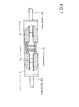
- Fig. 7 shows the fiber optic collimator system of the first embodiment.
- the optic fibers 2a and 2b with GRIN lenses 1a and 1b are inserted from both sides of the tubular collimator holder 9, and then adhered and fixed to attach the optical element 10 (in this case, the optical isolator) to the center.
- the optical element 10 in this case, the optical isolator
- Approximately 230 sets of the collimator systems are carefully fabricated.
- the horizontal displacements (position displacement D) with regard to the X and Y directions and the inclination angles (angle displacement) ⁇ x and ⁇ y of the opposed GRIN lenses are measured.
- Fig. 8 shows the accumulative counts of the horizontal displacements in the X and Y directions (position displacements).
- FIG. 9 shows the accumulative counts of the inclination displacements with regard to the X and Y directions (angle displacements) ⁇ x and ⁇ y.
- Figs. 8 and 9 show that the horizontal displacements are distributed with the peak of -0.3 ⁇ m and approximately ⁇ 1 ⁇ m width, and the inclination angle displacements are distributed with the peak of 0.65 degrees and approximately ⁇ 0.5 degrees width.
- the coupling losses for 90% or more of the total assembly are suppressed to 1dB or less as a target.
- the permitted horizontal displacement and the permitted inclination angle to achieve the target are obtained from Figs. 8 and 9 .
- the permitted horizontal displacement D is 0.80 ⁇ m and the permitted inclination angle ⁇ is 0.85 degrees (that is, 0.0148 radian). These are substituted in the equation (7) to calculate the necessary NA.
- NA 0.48
- the optical fiber with a GRIN lens was produced. 75.5 ml of silicon tetra-methoxide and 183.4 ml of isopropanol are mixed, 9.2 ml of 2N hydrochloric acid is added to the mixture, after agitation for 30 minutes, 30.8 ml of titanium tetra-n-butoxide was further added. After that, 0.01N ammonium water was added and a wet gel was obtained. After aging the wet gel for 2 days at 50°C, the wet gel was further immersed into 3N hydrochloric acid for 6 hours to give a concentration distribution of titanium to the gel.
- the gel was immersed into methanol, the hydrochloric component inside the gel was washed and dried to obtain a dry gel of approximately 10 mm in diameter.
- the temperature of the obtained dry gel is elevated at a speed of 10°C /hr starting from room temperature up to 350°C. After that, the temperature was elevated to 1200°C and sintered, and a transparent glass was obtained accordingly.
- the parent material was inserted into an electric furnace of the carbon heater at 0.04 mm/s, it was spun into an optical fiber having an outer dimension of 125 ⁇ m, and a GRIN lens shaped optical fiber was produced.
- the produced GRIN lens shaped optical fiber is fused and spliced to one end of a single mode optical fiber with the core diameter of 6.5 ⁇ m by using an electrical discharge fusion splicer.
- the optical fiber with a GRIN lens was obtained by cutting the GRIN lens to a cycle length of 350 ⁇ m which is a quarter of the meander cycle of a light propagating in the GRIN lens.
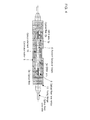
- Figs. 10 and 11 relate to the optical fiber collimator arrays of the second embodiment.
- the end portions of the GRIN lens attaching to the optical fiber are regularly arranged in eight (8) rows along periodic V-grooves 13 formed by chemical etching on the SiO 2 board 12. Further, these are regularly laminated in eight (8) steps, fixed to a frame 14, and thereby 8X8 GRIN lens collimator arrays were produced.
- the horizontal displacements in the X and Y directions (position displacement D) and the inclination angles (angle displacement) ⁇ x and ⁇ y were measured for each pair of the opposing GRIN lens.
- Fig. 12 shows the accumulative counts of the horizontal displacements in the X and Y directions (position displacement).
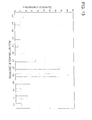
- Fig. 13 shows the accumulative counts of the inclination angles (angle displacement) ⁇ x and ⁇ y.
- the horizontal direction displacement distribution is unsymmetrical, with a peak of 0.6 ⁇ m.
- the inclination angle displacement distribution in unsymmetrical, with a peak of 0.8 degrees.
- the coupling loss is targeted to be suppressed up to 1dB or less in 90% or more of the total number of the GRIN lens pairs.
- the permitted horizontal position displacement and the permitted inclination angle to achieve the target are measured from Figs. 12 and 13 , the horizontal position displacement D resulted in 1.0 ⁇ m, and the inclination angle ⁇ resulted in 1.0 degrees (that is, 0.0175 radian). These are substituted in the equation (7) to calculate the necessary NA.
- the optical fiber with a GRIN lens was produced. 75.5 ml of silicon tetra-methoxide and 183.4 ml of isopropanol were mixed, 9.2 ml of 2N hydrochloric acid was added to the mixture, and after agitating the mixture for 30 minutes, 30.8 ml of titanium tetra-n-butoxide was further added. After that, 0.01N ammonium water was added and a wet gel was obtained. After aging the wet gel for 2 days at 50°C, the wet gel was further immersed into 6N hydrochloric acid for 2 hours to give a concentration distribution of titanium to the gel.
- the gel was immersed into methanol, and the hydrochloric component inside the gel was washed. After that, the gel was immersed into 6N hydrochloric acid for 20 minutes, and the second concentration distribution is given in the same manner as the first time, by immersing the gel into methanol, washing with the hydrochloric acid, and drying. After that, the gel was immersed into 6N hydrochloric acid for 8 minutes, and the third concentration distribution was given in the same manner as the first time, by immersing the gel into methanol, washing with the hydrochloric acid, and drying to obtain a dry gel of approximately 10 mm in diameter. The temperature of the obtained dry gel was elevated at a speed of 10°C/hr starting from room temperature up to 350°C.
- the parent material was inserted into an electric furnace of the carbon heater at 0.04mm/s, it was spun into an optical fiber having the outer dimension of 125 ⁇ m, and a GRIN lens shaped optical fiber was produced.
- the produced GRIN lens shaped optical fiber was fused and spliced to one end of a single mode optical fiber with the core radius of 6.5 ⁇ m by using the electrical discharge fusion splicer. After that, an optical fiber with a GRIN lens was obtained by cutting the GRIN lens to a cycle length of 295 ⁇ m which is a quarter of the meander cycle of a light propagating in the GRIN lens.
- the optical fiber collimator array system of Fig. 11 was fabricated, and further, the optical fiber collimator array system of Fig. 3 was produced.
- the coupling losses of all channels are measured, and the high coupling efficiency in which the coupling losses are 1dB or less were obtained for all of the channels (pairs of optical fibers with GRIN lenses).
Landscapes
- Physics & Mathematics (AREA)
- General Physics & Mathematics (AREA)
- Optics & Photonics (AREA)
- Engineering & Computer Science (AREA)
- Plasma & Fusion (AREA)
- Mathematical Physics (AREA)
- Astronomy & Astrophysics (AREA)
- Chemical & Material Sciences (AREA)
- Crystallography & Structural Chemistry (AREA)
- Optical Couplings Of Light Guides (AREA)
Priority Applications (1)
| Application Number | Priority Date | Filing Date | Title |
|---|---|---|---|
| EP11177327.1A EP2386887B1 (fr) | 2005-04-05 | 2005-04-05 | Procédé de fabrication d'un système d'ensemble de collimateur à fibres optiques |
Applications Claiming Priority (3)
| Application Number | Priority Date | Filing Date | Title |
|---|---|---|---|
| EP05728885.4A EP1868017B1 (fr) | 2005-04-05 | 2005-04-05 | Procedes de production d'un systeme de collimateur a fibre optique |
| EP11177327.1A EP2386887B1 (fr) | 2005-04-05 | 2005-04-05 | Procédé de fabrication d'un système d'ensemble de collimateur à fibres optiques |
| PCT/JP2005/006638 WO2006109348A1 (fr) | 2005-04-05 | 2005-04-05 | Systeme de collimateur a fibre optique, reseau de collimateurs a fibre optique et leurs procedes de production |
Related Parent Applications (1)
| Application Number | Title | Priority Date | Filing Date |
|---|---|---|---|
| EP05728885.4 Division | 2005-04-05 |
Publications (2)
| Publication Number | Publication Date |
|---|---|
| EP2386887A1 true EP2386887A1 (fr) | 2011-11-16 |
| EP2386887B1 EP2386887B1 (fr) | 2013-10-02 |
Family
ID=37086646
Family Applications (2)
| Application Number | Title | Priority Date | Filing Date |
|---|---|---|---|
| EP11177327.1A Expired - Lifetime EP2386887B1 (fr) | 2005-04-05 | 2005-04-05 | Procédé de fabrication d'un système d'ensemble de collimateur à fibres optiques |
| EP05728885.4A Expired - Lifetime EP1868017B1 (fr) | 2005-04-05 | 2005-04-05 | Procedes de production d'un systeme de collimateur a fibre optique |
Family Applications After (1)
| Application Number | Title | Priority Date | Filing Date |
|---|---|---|---|
| EP05728885.4A Expired - Lifetime EP1868017B1 (fr) | 2005-04-05 | 2005-04-05 | Procedes de production d'un systeme de collimateur a fibre optique |
Country Status (6)
| Country | Link |
|---|---|
| US (1) | US7357005B2 (fr) |
| EP (2) | EP2386887B1 (fr) |
| JP (1) | JP4080517B2 (fr) |
| KR (1) | KR100955619B1 (fr) |
| CN (1) | CN100501467C (fr) |
| WO (1) | WO2006109348A1 (fr) |
Families Citing this family (38)
| Publication number | Priority date | Publication date | Assignee | Title |
|---|---|---|---|---|
| US7357005B2 (en) * | 2005-04-05 | 2008-04-15 | Toyo Glass Co., Ltd. | Fiber optic collimator system, fiber optic collimator array, and manufacturing method of the fiber optic collimator system and fiber optic collimator array system |
| US7660502B1 (en) * | 2006-07-12 | 2010-02-09 | Wavefront Research, Inc. | Optical interconnect and connector devices |
| TWI460481B (zh) * | 2009-09-21 | 2014-11-11 | Hon Hai Prec Ind Co Ltd | 光纖組件 |
| US8520989B2 (en) * | 2010-03-19 | 2013-08-27 | Corning Incorporated | Fiber optic interface devices for electronic devices |
| CN102792200A (zh) * | 2010-03-19 | 2012-11-21 | 惠普发展公司,有限责任合伙企业 | 光学星形耦合器 |
| US8727637B2 (en) * | 2010-03-19 | 2014-05-20 | Corning Incorporated | Fiber optic interface devices for electronic devices |
| JP2013522692A (ja) * | 2010-03-19 | 2013-06-13 | コーニング インコーポレイテッド | 並進可能なフェルールを備えた光ファイバインタフェース装置 |
| JP2013522689A (ja) * | 2010-03-19 | 2013-06-13 | コーニング インコーポレイテッド | 電子装置用スモールフォームファクタ光ファイバインタフェース組立体 |
| US20110229077A1 (en) * | 2010-03-19 | 2011-09-22 | Davide Domenico Fortusini | Small-form-factor fiber optic interface devices with an internal lens |
| US8781273B2 (en) | 2010-12-07 | 2014-07-15 | Corning Cable Systems Llc | Ferrule assemblies, connector assemblies, and optical couplings having coded magnetic arrays |
| US8774577B2 (en) | 2010-12-07 | 2014-07-08 | Corning Cable Systems Llc | Optical couplings having coded magnetic arrays and devices incorporating the same |
| WO2012099769A2 (fr) | 2011-01-20 | 2012-07-26 | Corning Incorporated | Ensembles virole de réceptacle comportant des lentilles à indice de gradient et connecteurs de fibres optiques les utilisant |
| WO2013039768A2 (fr) | 2011-09-13 | 2013-03-21 | Corning Cable Systems Llc | Ensembles support de lentilles à translation utilisant des zones de relief d'alésage, et connecteurs optiques les intégrant |
| US8734024B2 (en) | 2011-11-28 | 2014-05-27 | Corning Cable Systems Llc | Optical couplings having a coded magnetic array, and connector assemblies and electronic devices having the same |
| EP2788806A2 (fr) | 2011-12-09 | 2014-10-15 | Corning Optical Communications LLC | Porte-lentille à gradient d'indice (grin) à élément(s) d'alignement de rainure et surface de réflexion interne totale (tir), et composants, connecteurs, et procédés associés |
| WO2013086117A2 (fr) | 2011-12-09 | 2013-06-13 | Corning Cable Systems Llc | Porte-lentilles à gradient d'indice (grin) utilisant une ou plusieurs caractéristiques d'alignement par rainures dans un couvercle à renfoncement et des éléments en une seule pièce, connecteurs et procédés |
| US10114174B2 (en) | 2012-05-31 | 2018-10-30 | Corning Optical Communications LLC | Optical connectors and optical coupling systems having a translating element |
| US9151912B2 (en) | 2012-06-28 | 2015-10-06 | Corning Cable Systems Llc | Optical fiber segment holders including shielded optical fiber segments, connectors, and methods |
| US9304265B2 (en) | 2012-07-26 | 2016-04-05 | Corning Cable Systems Llc | Fiber optic connectors employing moveable optical interfaces with fiber protection features and related components and methods |
| US9195008B2 (en) | 2013-02-26 | 2015-11-24 | Winchester Electronics Corporation | Expanded beam optical connector and method of making the same |
| JP2016512654A (ja) * | 2013-03-12 | 2016-04-28 | コーニンクレッカ フィリップス エヌ ヴェKoninklijke Philips N.V. | バイオセンサ用u字形磁石 |
| WO2014209671A2 (fr) | 2013-06-25 | 2014-12-31 | Corning Optical Communications LLC | Fiche optique possédant un couvercle de translation et une prise complémentaire |
| MX361813B (es) * | 2013-07-22 | 2018-12-14 | Adc Telecommunications Inc | Conector de fibra óptica de haz expandido, conjunto de cable y métodos para su manufactura. |
| US9291775B2 (en) * | 2014-02-18 | 2016-03-22 | Corning Optical Communications LLC | Optical fiber connector with achromatic grin lens |
| US9733440B2 (en) | 2014-04-29 | 2017-08-15 | Corning Incorporated | Optical connectors for coupling light sources to optical fibers |
| EP3198317A1 (fr) | 2014-09-23 | 2017-08-02 | Corning Optical Communications LLC | Connecteurs optiques et réceptacles optiques complémentaires comportant une fixation magnétique |
| JP6878770B2 (ja) * | 2016-04-05 | 2021-06-02 | 東洋製罐グループホールディングス株式会社 | レンズ付き光ファイバ及び光結合器 |
| JP2018054870A (ja) * | 2016-09-29 | 2018-04-05 | 日本電気株式会社 | 光伝送装置 |
| CN107121265B (zh) * | 2017-05-10 | 2020-05-26 | 深圳市惠富康光通信有限公司 | 一种C-lens装配工艺的检测设备和控制方法 |
| CN108803065B (zh) * | 2018-06-06 | 2021-03-26 | 上海飞博激光科技有限公司 | 一种密集光纤阵列光谱合束装置及方法 |
| JP7213499B2 (ja) * | 2018-08-02 | 2023-01-27 | 株式会社中原光電子研究所 | 光結合器 |
| US11327250B1 (en) * | 2019-03-08 | 2022-05-10 | Wavefront Research, Inc. | Optical interconnect devices |
| CN111650690A (zh) * | 2020-05-10 | 2020-09-11 | 桂林电子科技大学 | 一种基于双包层光纤的微准直器 |
| DK3964888T3 (da) * | 2020-09-03 | 2024-07-29 | Asml Netherlands Bv | Bredbåndsstrålingsgenerator med hul kerne baseret på fotoniske krystalfibre |
| CN118465928A (zh) * | 2023-02-08 | 2024-08-09 | 福州高意通讯有限公司 | 具有多个输入和输出的波分复用器 |
| WO2024190580A1 (fr) * | 2023-03-16 | 2024-09-19 | 株式会社島津製作所 | Dispositif à fibre optique, procédé de fabrication de dispositif à fibre optique et dispositif laser |
| US12571967B2 (en) * | 2023-03-31 | 2026-03-10 | Corning Research & Development Corporation | Optical couplers with gradient-index lenses and methods of fabricating the same using optical radiation to control pitch |
| CN118465929B (zh) * | 2024-07-15 | 2024-10-11 | 上海拜安传感技术有限公司 | 一种grin光纤准直器的设计方法 |
Citations (5)
| Publication number | Priority date | Publication date | Assignee | Title |
|---|---|---|---|---|
| US4213677A (en) | 1976-10-13 | 1980-07-22 | Nippon Selfoc Company, Limited | Light coupling and branching device using light focusing transmission body |
| US4701011A (en) | 1985-01-15 | 1987-10-20 | American Telephone And Telegraph Company, At&T Bell Laboratories | Multimode fiber-lens optical coupler |
| US5384874A (en) | 1992-06-24 | 1995-01-24 | Sumitomo Electric Industries, Ltd. | Optical fiber rod lens device and method of making same |
| EP1260841A1 (fr) * | 2001-05-19 | 2002-11-27 | Lucent Technologies Inc. | Lentilles en fibre optique à gradient d'indice |
| US20040137236A1 (en) * | 2003-01-10 | 2004-07-15 | Olympus Corporation | Optical system for optical communications and method of manufacturing the same |
Family Cites Families (11)
| Publication number | Priority date | Publication date | Assignee | Title |
|---|---|---|---|---|
| US4962988A (en) * | 1989-07-10 | 1990-10-16 | Optomec Design Company | Termination interface structure and method for joining an optical fiber to a graded index rod lens |
| US5757993A (en) * | 1995-06-05 | 1998-05-26 | Jds Fitel Inc. | Method and optical system for passing light between an optical fiber and grin lens |
| JPH11100216A (ja) * | 1997-07-30 | 1999-04-13 | Olympus Optical Co Ltd | 屈折率分布型光学素子とその製造方法 |
| JP2001159702A (ja) * | 1999-12-01 | 2001-06-12 | Nippon Sheet Glass Co Ltd | 屈折率分布型レンズ |
| US20020016840A1 (en) * | 2000-05-12 | 2002-02-07 | Shai Herzog | Applying recursive policy for scoping of administration of policy based networking |
| US20020150333A1 (en) * | 2001-02-17 | 2002-10-17 | Reed William Alfred | Fiber devices using grin fiber lenses |
| JP2002372604A (ja) | 2001-04-03 | 2002-12-26 | Fujikura Ltd | コリメータレンズ、ファイバコリメータ、及び光部品 |
| CN1228655C (zh) * | 2001-04-03 | 2005-11-23 | 株式会社藤仓 | 平行光管透镜、纤维平行光管以及光学部件 |
| EP1312952A1 (fr) * | 2001-11-15 | 2003-05-21 | Nippon Sheet Glass Co.,Ltd. | Collimateur à fibres optiques utilisant une lentille à gradient d'indice |
| JP2004302292A (ja) * | 2003-03-31 | 2004-10-28 | Hoya Corp | 光ファイバ端末とその作製方法並びに光結合器及び光部品 |
| US7357005B2 (en) * | 2005-04-05 | 2008-04-15 | Toyo Glass Co., Ltd. | Fiber optic collimator system, fiber optic collimator array, and manufacturing method of the fiber optic collimator system and fiber optic collimator array system |
-
2005
- 2005-04-05 US US10/569,278 patent/US7357005B2/en not_active Expired - Lifetime
- 2005-04-05 EP EP11177327.1A patent/EP2386887B1/fr not_active Expired - Lifetime
- 2005-04-05 JP JP2006519029A patent/JP4080517B2/ja not_active Expired - Fee Related
- 2005-04-05 CN CNB2005800491055A patent/CN100501467C/zh not_active Expired - Lifetime
- 2005-04-05 WO PCT/JP2005/006638 patent/WO2006109348A1/fr not_active Ceased
- 2005-04-05 KR KR1020077017358A patent/KR100955619B1/ko not_active Expired - Fee Related
- 2005-04-05 EP EP05728885.4A patent/EP1868017B1/fr not_active Expired - Lifetime
Patent Citations (5)
| Publication number | Priority date | Publication date | Assignee | Title |
|---|---|---|---|---|
| US4213677A (en) | 1976-10-13 | 1980-07-22 | Nippon Selfoc Company, Limited | Light coupling and branching device using light focusing transmission body |
| US4701011A (en) | 1985-01-15 | 1987-10-20 | American Telephone And Telegraph Company, At&T Bell Laboratories | Multimode fiber-lens optical coupler |
| US5384874A (en) | 1992-06-24 | 1995-01-24 | Sumitomo Electric Industries, Ltd. | Optical fiber rod lens device and method of making same |
| EP1260841A1 (fr) * | 2001-05-19 | 2002-11-27 | Lucent Technologies Inc. | Lentilles en fibre optique à gradient d'indice |
| US20040137236A1 (en) * | 2003-01-10 | 2004-07-15 | Olympus Corporation | Optical system for optical communications and method of manufacturing the same |
Non-Patent Citations (1)
| Title |
|---|
| P.B.O'CONNOR ET AL., ELECTRON. LETT., vol. 13, 1977, pages 170 - 171 |
Also Published As
| Publication number | Publication date |
|---|---|
| EP1868017A4 (fr) | 2010-12-22 |
| CN100501467C (zh) | 2009-06-17 |
| EP1868017B1 (fr) | 2013-06-12 |
| EP1868017A1 (fr) | 2007-12-19 |
| KR20080005351A (ko) | 2008-01-11 |
| CN101156099A (zh) | 2008-04-02 |
| US7357005B2 (en) | 2008-04-15 |
| US20070147733A1 (en) | 2007-06-28 |
| KR100955619B1 (ko) | 2010-05-03 |
| JP4080517B2 (ja) | 2008-04-23 |
| HK1108490A1 (en) | 2008-05-09 |
| JPWO2006109348A1 (ja) | 2008-10-02 |
| WO2006109348A1 (fr) | 2006-10-19 |
| EP2386887B1 (fr) | 2013-10-02 |
Similar Documents
| Publication | Publication Date | Title |
|---|---|---|
| EP2386887B1 (fr) | Procédé de fabrication d'un système d'ensemble de collimateur à fibres optiques | |
| KR100833820B1 (ko) | 광파이버 결합부품 | |
| US6078716A (en) | Thermally expanded multiple core fiber | |
| CA1279515C (fr) | Fibre optique a extremite elargie et dispositifs de couplage connexes | |
| CN1307448C (zh) | 光束弯曲装置及其制造方法 | |
| US7603008B2 (en) | Optical fiber coupling part and manufacturing method thereof | |
| US12366710B2 (en) | Fiber optic ferrule and interface for coupling hollow-core and solid-core optical fibers | |
| HK1163259B (en) | Manufacturing method of a fiber optic collimator array system | |
| HK1163259A1 (en) | Manufacturing method of a fiber optic collimator array system | |
| HK1108490B (en) | Production method of an optical fiber collimator system | |
| JPH0854538A (ja) | 微小レンズ付光ファイバ端末の製造方法 | |
| US20030026535A1 (en) | Optical fiber collimators and their manufacture | |
| JP2003337234A (ja) | ファイバ型光デバイス | |
| HK1090430B (en) | Optical fiber coupling component | |
| HK1144966B (en) | Optical fiber coupling part comprising grin lenses | |
| JP2003241024A (ja) | 縦続接続型界分布変換素子およびその縦続接続型界分布変換素子を用いた光機能装置 |
Legal Events
| Date | Code | Title | Description |
|---|---|---|---|
| AC | Divisional application: reference to earlier application |
Ref document number: 1868017 Country of ref document: EP Kind code of ref document: P |
|
| AK | Designated contracting states |
Kind code of ref document: A1 Designated state(s): DE FR GB |
|
| PUAI | Public reference made under article 153(3) epc to a published international application that has entered the european phase |
Free format text: ORIGINAL CODE: 0009012 |
|
| RIN1 | Information on inventor provided before grant (corrected) |
Inventor name: MATSUMURA, HIROYOSHI Inventor name: ACHIWA, TORU Inventor name: SUZUKI, TARO |
|
| RIN1 | Information on inventor provided before grant (corrected) |
Inventor name: SUZUKI, TARO Inventor name: ACHIWA, TORU Inventor name: MATSUMURA, HIROYOSHI |
|
| 17P | Request for examination filed |
Effective date: 20120510 |
|
| REG | Reference to a national code |
Ref country code: HK Ref legal event code: DE Ref document number: 1163259 Country of ref document: HK |
|
| GRAP | Despatch of communication of intention to grant a patent |
Free format text: ORIGINAL CODE: EPIDOSNIGR1 |
|
| RIC1 | Information provided on ipc code assigned before grant |
Ipc: G02B 3/00 20060101ALN20121023BHEP Ipc: G02B 6/32 20060101AFI20121023BHEP |
|
| RIC1 | Information provided on ipc code assigned before grant |
Ipc: G02B 6/32 20060101AFI20130314BHEP Ipc: G02B 3/00 20060101ALN20130314BHEP |
|
| RIN1 | Information on inventor provided before grant (corrected) |
Inventor name: SUZUKI, TARO Inventor name: MATSUMURA, HIROYOSHI Inventor name: ACHIWA, TORU |
|
| GRAP | Despatch of communication of intention to grant a patent |
Free format text: ORIGINAL CODE: EPIDOSNIGR1 |
|
| RAP1 | Party data changed (applicant data changed or rights of an application transferred) |
Owner name: TOYO GLASS CO., LTD. |
|
| RIC1 | Information provided on ipc code assigned before grant |
Ipc: G02B 6/32 20060101AFI20130423BHEP Ipc: G02B 3/00 20060101ALN20130423BHEP |
|
| INTG | Intention to grant announced |
Effective date: 20130515 |
|
| RIN1 | Information on inventor provided before grant (corrected) |
Inventor name: ACHIWA, TORU Inventor name: MATSUMURA, HIROYOSHI Inventor name: SUZUKI, TARO |
|
| RAP1 | Party data changed (applicant data changed or rights of an application transferred) |
Owner name: TOYO GLASS CO., LTD. |
|
| GRAS | Grant fee paid |
Free format text: ORIGINAL CODE: EPIDOSNIGR3 |
|
| GRAA | (expected) grant |
Free format text: ORIGINAL CODE: 0009210 |
|
| AC | Divisional application: reference to earlier application |
Ref document number: 1868017 Country of ref document: EP Kind code of ref document: P |
|
| AK | Designated contracting states |
Kind code of ref document: B1 Designated state(s): DE FR GB |
|
| REG | Reference to a national code |
Ref country code: GB Ref legal event code: FG4D |
|
| RAP2 | Party data changed (patent owner data changed or rights of a patent transferred) |
Owner name: TOYO SEIKAN GROUP HOLDINGS, LTD. |
|
| REG | Reference to a national code |
Ref country code: DE Ref legal event code: R082 Ref document number: 602005041427 Country of ref document: DE Representative=s name: HASELTINE LAKE LLP, DE |
|
| REG | Reference to a national code |
Ref country code: DE Ref legal event code: R096 Ref document number: 602005041427 Country of ref document: DE Effective date: 20131205 |
|
| REG | Reference to a national code |
Ref country code: GB Ref legal event code: 732E Free format text: REGISTERED BETWEEN 20131230 AND 20131231 |
|
| REG | Reference to a national code |
Ref country code: DE Ref legal event code: R082 Ref document number: 602005041427 Country of ref document: DE Representative=s name: HASELTINE LAKE LLP, DE Effective date: 20131202 Ref country code: DE Ref legal event code: R081 Ref document number: 602005041427 Country of ref document: DE Owner name: TOYO SEIKAN GROUP HOLDINGS, LTD., JP Free format text: FORMER OWNER: TOYO GLASS CO. LTD., TOKIO/TOKYO, JP Effective date: 20131202 Ref country code: DE Ref legal event code: R081 Ref document number: 602005041427 Country of ref document: DE Owner name: TOYO SEIKAN GROUP HOLDINGS, LTD., TOKYO/TOKIO, JP Free format text: FORMER OWNER: TOYO GLASS CO. LTD., TOKIO/TOKYO, JP Effective date: 20131202 |
|
| REG | Reference to a national code |
Ref country code: HK Ref legal event code: GR Ref document number: 1163259 Country of ref document: HK |
|
| REG | Reference to a national code |
Ref country code: DE Ref legal event code: R097 Ref document number: 602005041427 Country of ref document: DE |
|
| PLBE | No opposition filed within time limit |
Free format text: ORIGINAL CODE: 0009261 |
|
| STAA | Information on the status of an ep patent application or granted ep patent |
Free format text: STATUS: NO OPPOSITION FILED WITHIN TIME LIMIT |
|
| 26N | No opposition filed |
Effective date: 20140703 |
|
| REG | Reference to a national code |
Ref country code: DE Ref legal event code: R097 Ref document number: 602005041427 Country of ref document: DE Effective date: 20140703 |
|
| REG | Reference to a national code |
Ref country code: FR Ref legal event code: PLFP Year of fee payment: 12 |
|
| REG | Reference to a national code |
Ref country code: FR Ref legal event code: PLFP Year of fee payment: 13 |
|
| REG | Reference to a national code |
Ref country code: FR Ref legal event code: PLFP Year of fee payment: 14 |
|
| REG | Reference to a national code |
Ref country code: DE Ref legal event code: R082 Ref document number: 602005041427 Country of ref document: DE Representative=s name: HL KEMPNER PATENTANWAELTE, SOLICITORS (ENGLAND, DE Ref country code: DE Ref legal event code: R082 Ref document number: 602005041427 Country of ref document: DE Representative=s name: HL KEMPNER PATENTANWALT, RECHTSANWALT, SOLICIT, DE |
|
| PGFP | Annual fee paid to national office [announced via postgrant information from national office to epo] |
Ref country code: GB Payment date: 20240419 Year of fee payment: 20 |
|
| PGFP | Annual fee paid to national office [announced via postgrant information from national office to epo] |
Ref country code: DE Payment date: 20240418 Year of fee payment: 20 |
|
| PGFP | Annual fee paid to national office [announced via postgrant information from national office to epo] |
Ref country code: FR Payment date: 20240426 Year of fee payment: 20 |
|
| REG | Reference to a national code |
Ref country code: DE Ref legal event code: R071 Ref document number: 602005041427 Country of ref document: DE |
|
| REG | Reference to a national code |
Ref country code: GB Ref legal event code: PE20 Expiry date: 20250404 |
|
| PG25 | Lapsed in a contracting state [announced via postgrant information from national office to epo] |
Ref country code: GB Free format text: LAPSE BECAUSE OF EXPIRATION OF PROTECTION Effective date: 20250404 |