EP2386921A2 - Verfahren zum Trennen und Erhalten der statischen und dynamischen Abschnitte einer Steuerungsanwendung - Google Patents
Verfahren zum Trennen und Erhalten der statischen und dynamischen Abschnitte einer Steuerungsanwendung Download PDFInfo
- Publication number
- EP2386921A2 EP2386921A2 EP11165993A EP11165993A EP2386921A2 EP 2386921 A2 EP2386921 A2 EP 2386921A2 EP 11165993 A EP11165993 A EP 11165993A EP 11165993 A EP11165993 A EP 11165993A EP 2386921 A2 EP2386921 A2 EP 2386921A2
- Authority
- EP
- European Patent Office
- Prior art keywords
- volatile memory
- data objects
- data object
- dynamic
- static
- Prior art date
- Legal status (The legal status is an assumption and is not a legal conclusion. Google has not performed a legal analysis and makes no representation as to the accuracy of the status listed.)
- Granted
Links
Images

Classifications
-
- G—PHYSICS
- G05—CONTROLLING; REGULATING
- G05B—CONTROL OR REGULATING SYSTEMS IN GENERAL; FUNCTIONAL ELEMENTS OF SUCH SYSTEMS; MONITORING OR TESTING ARRANGEMENTS FOR SUCH SYSTEMS OR ELEMENTS
- G05B19/00—Program-control systems
- G05B19/02—Program-control systems electric
- G05B19/04—Program control other than numerical control, i.e. in sequence controllers or logic controllers
- G05B19/042—Program control other than numerical control, i.e. in sequence controllers or logic controllers using digital processors
-
- G—PHYSICS
- G05—CONTROLLING; REGULATING
- G05B—CONTROL OR REGULATING SYSTEMS IN GENERAL; FUNCTIONAL ELEMENTS OF SUCH SYSTEMS; MONITORING OR TESTING ARRANGEMENTS FOR SUCH SYSTEMS OR ELEMENTS
- G05B2219/00—Program-control systems
- G05B2219/20—Pc systems
- G05B2219/24—Pc safety
- G05B2219/24137—Non volatile memory to store program on power loss
-
- G—PHYSICS
- G05—CONTROLLING; REGULATING
- G05B—CONTROL OR REGULATING SYSTEMS IN GENERAL; FUNCTIONAL ELEMENTS OF SUCH SYSTEMS; MONITORING OR TESTING ARRANGEMENTS FOR SUCH SYSTEMS OR ELEMENTS
- G05B2219/00—Program-control systems
- G05B2219/20—Pc systems
- G05B2219/24—Pc safety
- G05B2219/24139—Recovery from power loss, failure
Definitions
- the subject matter disclosed herein relates generally to industrial controllers for controlling industrial processes or machinery, and in particular to a method of allocating and persisting memory in an industrial controller.
- Industrial controllers are special purpose computers used for controlling factory automation and the like.
- the control program executed by the industrial controller is normally highly customized to a particular control application.
- Special control languages such as "relay ladder logic" are normally used to facilitate programming of the device.
- a processor of the industrial controller examines a series of inputs reflecting the status of a controlled process.
- the control program uses the series of inputs to set or reset internal states within the processor. The combination of inputs and internal states are used to set outputs affecting the controlled process.
- Industrial controllers often operate in environments where unexpected power interruptions may occur. For example, an operator or maintenance personnel may enter a restricted area or the controlled process, or another controlled process operating nearby may experience a fault condition, resulting in the power being removed from the controller.
- a power interruption may result in significant costs associated with lost production or potential complications of resetting a process. Consequently, the ability of the controller to quickly resume control of the process after a power loss can result in significant cost savings.
- RAM Random Access Memory
- controllers are now expected to retain significant amounts of information, including symbolic access to data and historical information, such as alarms, faults, or other events. Controllers also execute increasingly complex algorithms and control programs, requiring an increasing quantity of data to be persisted.
- the subject matter disclosed herein describes a method of allocating and persisting memory in an industrial controller without requiring a battery backup or large capacitive storage system.
- the present method first places data objects into non-volatile memory.
- Each data object is identified as a static or dynamic object
- a static data object is a data object having a value that does not change frequently
- a dynamic data object is a data object having a value that does change frequently.
- the static objects are further classified by whether frequent access of that data object is required.
- the dynamic data objects and those static data objects requiring frequent access are stored in volatile memory.
- changes to the static objects are preferably stored directly in non-volatile memory or recorded in a log stored in non-volatile memory. Changes to the dynamic objects are updated directly in volatile memory.
- a method of retaining a plurality of data objects in memory in an industrial controller having both a volatile memory and a non-volatile memory classifies each of the data objects as a static data object or a dynamic object.
- Each static data object is changed at a frequency less than a preselected threshold frequency and each dynamic object is changed at a frequency greater than a preselected threshold frequency.
- a data object may have at least a first and a second data element, wherein the first data element is classified as a static data object and the second data element is classified as a dynamic data object.
- Each of the static data objects is stored in non-volatile memory, and each dynamic data object and at least a portion of the static data objects are stored in volatile memory.
- the dynamic data object When each dynamic data object changes, the dynamic data object is updated in the volatile memory. For the portion of static data objects stored in volatile memory, changes of the static data objects are tracked and updated in the volatile memory when the static data object changes. The present value of each dynamic object in the volatile memory is copied to the non-volatile memory when power is removed from the controller.
- the data objects are classified as static or dynamic to identify data objects as either frequently or infrequently changed at run-time of the controller.
- the number of data objects to be persisted during a power loss is subsequently minimized by copying only those data objects that are frequently changed at run-time.
- each of the dynamic data objects and the portion of static data objects stored in the volatile memory are copied from the non-volatile memory to the volatile memory when power is restored to the controller.
- the status of the data objects of the controller may be restored when power is reapplied to the controller.
- tracking the change of the static data objects stored in volatile memory further comprises the step of updating the static data object in the non-volatile memory prior to updating the static data object in the volatile memory.
- tracking the change of the static data objects stored in volatile memory comprises the steps of storing a record of each change into the non-volatile memory and restoring the changes to the static data objects stored in the volatile memory according to the record of changes after the static data objects are copied from the non-volatile memory to the volatile memory when power is restored to the controller.
- changes to the static data objects are either recorded in the non-volatile memory as they occur or a record of changes to the static data is kept and the changes are reapplied after reloading the base set of data objects into volatile memory.
- a portion of the non-volatile memory equal to or greater in size than number of dynamic data objects may be reserved.
- the present value of each dynamic object in the volatile memory is then stored in the reserved portion of the non-volatile memory at a power loss.
- the dynamic data objects may be transferred as a block of data to non-volatile memory to facilitate storing the data objects during a power loss.
- a database is embedded in the non-volatile memory device and the embedded database stores the relation between a first address corresponding to each data object in the volatile memory and a second address corresponding to the data object in non-volatile memory.
- the embedded database stores the relation between a name corresponding to each data object in the volatile memory and an address corresponding to the data object in non-volatile memory.
- the rate at which each dynamic data object and each static data object is updated in memory is monitored.
- the rate at which each dynamic data object and each static data object is updated in memory is then compared against the threshold frequency, and the data objects are reclassified as either a static data object or a dynamic object according to the comparison of the rate at which each data object is updated versus the threshold frequency.
- the allocation of data objects between static and dynamic may be updated as the industrial controller is executing according to the actual usage of each data object.
- the industrial control system also includes a non-volatile memory device storing each of the data objects and a volatile memory storing each dynamic data object and at least a portion of the static data objects. At least one routine executing on the processor tracks the change of each static data object and stores the new static data object in the volatile memory when the static data object changes.
- the routine also monitors a low voltage signal and, if the low voltage signal is active, copies the present value of each dynamic data object from the volatile memory to the non-volatile memory. Additionally, the routine may copy each of the dynamic data objects and the portion of static data objects stored in volatile memory from the non-volatile memory to the volatile memory when power is restored to the processor.
- the data objects in an industrial control system are classified as static and dynamic objects to identify those data objects that are frequently changed at run-time of the controller, resulting in a minimum number of data objects to be persisted during a power loss.
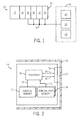
- FIG. 1 is a block diagram of an industrial controller incorporating a method of persisting control data according to one embodiment of the present invention
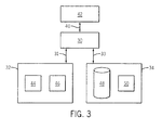
- FIG. 2 is a block diagram of a processor module of FIG. 1 ;
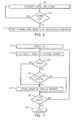
- FIG. 3 is a block diagram representation of the interconnections for persisting control data according to one embodiment of the present invention.
- FIG. 4 is a flowchart illustrating the process of initially loading data objects into memory
- FIG. 5 is a flowchart illustrating changing the value of a data object
- FIG. 6 is a flowchart illustrating persisting data objects at a power loss on the controller
- FIG. 7 is a flowchart illustrating restoring data objects when power is restored to the controller.
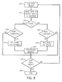
- FIG. 8 is a flowchart illustrating dynamic allocation of data objects as static or dynamic.
- an industrial control system 10 typically includes a power supply 12, a processor module 14, and multiple I/O modules 16.
- the I/O modules 16 connect via I/O signal lines 18 to I/O devices 20 in a controlled process 22.
- each of the modules, 14 and 16 may be inserted into a rack 15 and communicate via a backplane 17.
- the industrial control system 10 may include many configurations as is known to one skilled in the art.
- the number of I/O modules 16 used may vary according to the configuration of the control system 10.
- the I/O modules 16 can be plugged into or removed from the rack 15 for easy expandability and adaptability to configuration changes.
- the control system 10 may employ either a single or multiple processor modules 14 with either a single or multiple racks 15.
- the combination of processor modules 14 and racks 15 is defined according to the requirements of the control system 10 and the specific application.
- the processor module 14 includes a processor 30 configured to execute a program and to communicate with both a volatile memory device 32 and a non-volatile memory device 34.
- the processor 30 communicates by one or more busses, 31 and 33, between the processor 30 and each of the volatile and non-volatile devices, 32 and 34.
- the processor module 14 includes a connector 38 to connect the module 14 to the backplane 17.
- the processor 30 may send or receive signals across the backplane 17, such as I/O signals 36 to and from the I/O modules 16, shown in Fig. 1 .
- the processor 30 may also communicate via the backplane 17 with external devices over communication lines 40.
- the processor module 14 may include a communication port, not shown, on the module to directly communicate with an external device, such as a programming terminal 42 or other human interface. It is further contemplated, that the processor module may include multiple processors 30 with either a single processor persisting data objects or each processor 30 persisting a portion of the data objects.
- the memory on each of the volatile and non-volatile devices, 32 and 34 may be allocated, or partitioned, to define storage locations for data objects used by the program executing on the processor 30.
- the volatile memory device 32 includes a first segment 44 of memory to store dynamic data objects and a second segment 46 of memory to store static data objects.
- the non-volatile memory device 34 includes at least a first segment 48 to store data objects.
- the first segment 48 may store both static and dynamic data objects or, alternately, the first segment 48 may store only static data objects.
- An optional second segment 50 may be provided to store dynamic data objects. It is further contemplated that any of the memory segments, 44, 46, 48, or 50, may either be a single continuous range of memory addresses or be multiple ranges of memory addresses. Further, each memory segment, 44, 46, 48, or 50, may be implemented using either a single, or multiple, memory device, 32 or 34.
- the processor 30 executes a stored program to control an industrial process 22.
- the program includes data objects describing, for example, input signals, output signals, parameter settings, timer values, intermediate signals, and other internal states.
- the control system 10 may also include data objects not required for execution of the program such as user or maintenance manuals or data sheets stored in memory. The number and nature of the data objects in a program is dependent on the process 22 being controlled and the quantity of memory available in the control system 10.
- the program is developed on a programming terminal 42 and transmitted to the processor 30.
- the program may be developed or edited using any other suitable human-machine interface (HMI) device. As a program is developed or edited, data objects are identified as static or dynamic as indicated at step 100 in Fig. 4 .
- HMI human-machine interface
- a static data object is a data object that is written to at a rate below a predetermined threshold.
- a dynamic data object is a data object that is written to at a rate above a predetermined threshold.
- the predetermined threshold may be a fixed threshold based on, for example, a specific number of writes per shift or during a given time interval and may vary according to the process 22 being controlled.
- the predetermined threshold may be dependent on the specifications of the control system 10, including but not limited to, the clock frequency of the processor, the bandwidth of the data bus, 31 or 33, the speed at which the non-volatile memory may be written, and the rate at which the supply voltage decays upon power loss.
- memory for the data objects is allocated within the control system 10.
- addresses for each of the static data objects are allocated in non-volatile memory 34.
- addresses for each of the dynamic data objects may be allocated in non-volatile memory 34.
- a block of addresses may be allocated in the non-volatile memory 34 of sufficient length to store all of the dynamic data objects.
- a determination is made if each static data object must be frequently accessed. For example, a parameter of the control system 10 may initially be set and subsequently vary infrequently or not at all, resulting in designation as a static data object.
- the value of the parameter may require frequent read access by the program executing on the processor 30 to control the controlled process 22. Because volatile memory 32 can typically be accessed, or read from, at a faster rate than non-volatile memory 34 it is desirable to access the data object from volatile memory 32.
- memory addresses for both dynamic data objects and those static data objects requiring frequent access are allocated in the volatile memory 32.
- the volatile memory address for data objects allocated to both volatile and non-volatile memory is preferably stored in non-volatile memory along with the corresponding data object.
- step 110 changes in the value of both the static and dynamic data objects are managed during run-time.
- the value of one of the data objects changes and is received by a routine executing on the processor 30.
- the routine checks if the data object is static or dynamic, as previously determined according to step 100 in Fig. 4 . If the object is static, the routine checks whether the object requires frequent access as shown in step 118.
- the new value is updated in volatile memory 32, shown at step 114. If the data object is static, the change is tracked and updated in non-volatile memory 34 as discussed in more detail below. If the static data object requires frequent access, the new value is also updatedin the volatile memory 32, as shown by steps 114-118.
- Changes in the values of static data objects are first updated or tracked in non-volatile memory 34 and then updated in volatile memory 32 as needed.
- any change made to a static data object is first updated directly in the non-volatile memory 34. If the data object has also been allocated to volatile memory 32, the processor 30 subsequently copies the new value of the object to volatile memory 32.
- the processor 30 creates a record of changes made to the static data objects and stores the record of changes in non-volatile memory 34. As a result, either the static data object or a record of the change to the static data objects is saved in non-volatile memory 34 such that the current state of static data objects are already present in non-volatile memory 34 if a power loss occurs.
- a routine executing on the processor 30 monitors a power loss signal input to the processor 30.
- the control voltage supplied to the control system 10 is monitored, for example, by external circuitry or internally by a routine executing on the processor 30, to generate a power loss signal.. If the power loss signal indicates that the voltage is being removed from the control system 10, the present value of the dynamic data objects are copied from the volatile memory 32 to the non-volatile memory 34.
- Each dynamic data object may be copied to a corresponding memory address previously allocated in the non-volatile memory 34 or, optionally, a block transfer of portions or the entire set of dynamic data objects may be transferred to a corresponding block of addresses allocated in the non-volatile memory 34. Because changes to the static data objects have been either stored in or tracked and stored in the non-volatile memory 34 as the changes occur, there is no need to copy static data objects at power loss.
- a routine executing on the processor 30 retrieves the data objects from non-volatile memory 34.
- the routine determines whether each data object is static or dynamic and whether the static data objects are frequently accessed as shown in steps 134 and 136.
- the values of each of the dynamic data objects and each of the static data objects that are frequently accessed are restored from the non-volatile memory 34 to the volatile memory 32.
- the changes to static data objects may be tracked by establishing a base image of the static data objects in non-volatile memory 34 and recording a log, or a journal, of each of the new values for the static data objects as the static data object is changed.
- the log is maintained in non-volatile memory 34 such that the log need not be persisted at power loss.
- the base image initially includes predetermined default values for each of the static data objects.
- an identifier of which data object changed such as a memory address, programming label, or other suitable identifier
- the new value of the static data object are recorded in the log or journal.
- the command sent to the controller to initiate the change in the static data object may similarly be recorded in the log or journal.
- a routine executing on the processor 30 may reallocate data objects as either static or dynamic according to the frequency at which the data object changes.
- one of the data objects is identified by, for example, a pointer to the memory address of the data object or by reading the value of the data object.
- the rate at which the data object has been changed is read from memory at step 152.
- the routine for reallocating data objects may determine the rate at which the data object is changing.
- the routine determines whether the data object was previously allocated as a static or dynamic data object. If the data object was previously allocated as a static object, the routine determines whether the rate at which the object changes is greater than the threshold for identifying the object as a dynamic data object, as shown at step 156. If not, the data object remains a static data object. If the static object is being updated at a rate greater than the threshold for identifying the object as a dynamic data object, the data object is reclassified as a dynamic data object, as shown at step 158.
- the routine again determines whether the rate at which the object changes is greater than the threshold for identifying the object as a dynamic data object, as shown at step 162. If so, the data object remains a dynamic data object. If the dynamic object is being updated at a rate less than the threshold for identifying the object as a dynamic data object, the data object may be reclassified as a static data object, as shown at step 164. At step 160, if a data object has been reclassified based on the rate at which it has been changed, memory is reallocated for the data object in a manner similar to the original memory allocation as illustrated by Fig. 4 .
- the routine determines whether all of the data objects have been analyzed to determine whether each should be allocated as static or dynamic. If each data object has been analyzed, the routine ends as shown at step 168. If additional data objects need to be analyzed, the routine returns to step 150 and identifies the next data object to be analyzed.
- the routine is preferably a background routine executing at a periodic interval.
- a routine executing on the processor 30 periodically copy the changes from the log to the base image.
- the routine may execute periodically as a background task executing on the processor 30. As changes are copied from the log to the base image, the change is cleared from the log and the new values of the static data objects are incorporated into the base image.
- the log After a power loss and as power is restored, the log, along with the base image, is used to return each static data object to its state prior to the power loss.
- the value of each static data object from the base image is copied from non-volatile memory 34 to volatile memory 32.
- each entry in the log is replayed, from the oldest to the most recent, such that each change that was stored in the log is copied to the volatile memory 32 in the same sequence in which it was originally stored in the log.
- the log recorded commands sent to the controller the log is replayed such that the commands are reissued in the order they were received to similarly restore the static data objects in volatile memory to their state prior to power loss.
- changes to static data objects may be tracked by a status flag established for each of the static data objects which are stored in volatile memory 32.
- the status flag may be, for example, a bit that is selectively toggled between zero and one.
- the status flag may be stored in the volatile memory 32 along with the data object or, optionally, a separate block of memory may include status flags for each of the data objects.
- a background routine may be executed to periodically review the status flags for the static data objects and update the non-volatile memory locations for those static data objects that have changed. After updating the non-volatile memory location, the background routine clears the status flag.
- the value of any static data object having the status flag set is copied to non-volatile memory along with the values of the dynamic data objects.
- the present method first places data objects into non-volatile memory.
- Each data object that needs to be accessed at run-time is identified as a static or dynamic object.
- the static objects are first updated in the non-volatile memory and then stored in volatile memory while dynamic objects are updated directly in volatile memory. If power to the controller is removed, the present value of each dynamic data object is copied to non-volatile memory. When power to the controller is restored, the values of both the frequently accessed static and the dynamic data objects are copied from non-volatile memory to volatile memory.
- the static data objects may be written directly to both volatile and non-volatile memory devices, 32 and 34.
- a separate routine executing on the processor tracks used and unused memory locations. The routine similarly maintains a record of the corresponding memory addresses for a data object in both volatile and non-volatile memory.
- an embedded file system may be stored on the non-volatile memory device 34 for execution on the processor 30.
- the embedded file system manages the used and unused memory locations and maintains the record of the corresponding memory addresses for a data object in both volatile and non-volatile memory.
- a separate routine executing on the processor 30 interfaces with the file system to locate and store data objects in the file system.
- an embedded database may be stored on the non-volatile memory device 34 and is accessible by a routine executing on the processor 30.
- the embedded database manages the used and unused memory locations and maintains a relational record of the corresponding memory addresses for a data object in both volatile and non-volatile memory, 32 and 34.
- the relational record may store a first name or address for a data object in the volatile memory, a second name or address corresponding to the data object in non-volatile memory, or any combination of names, addresses, or other descriptors for each data object in volatile and non-volatile memory.
- a separate routine executing on the processor 30 interfaces with the embedded database to exploit the lookup capabilities of a database to facilitate efficient updates of and inserts to the static data objects.
Landscapes
- Physics & Mathematics (AREA)
- General Physics & Mathematics (AREA)
- Engineering & Computer Science (AREA)
- Automation & Control Theory (AREA)
- Techniques For Improving Reliability Of Storages (AREA)
- Power Sources (AREA)
Applications Claiming Priority (1)
| Application Number | Priority Date | Filing Date | Title |
|---|---|---|---|
| US12/780,308 US8566561B2 (en) | 2010-05-14 | 2010-05-14 | Method to separate and persist static and dynamic portions of a control application |
Publications (3)
| Publication Number | Publication Date |
|---|---|
| EP2386921A2 true EP2386921A2 (de) | 2011-11-16 |
| EP2386921A3 EP2386921A3 (de) | 2014-03-26 |
| EP2386921B1 EP2386921B1 (de) | 2017-03-01 |
Family
ID=44117767
Family Applications (1)
| Application Number | Title | Priority Date | Filing Date |
|---|---|---|---|
| EP11165993.4A Active EP2386921B1 (de) | 2010-05-14 | 2011-05-13 | Verfahren zum Trennen und Erhalten der statischen und dynamischen Abschnitte einer Steuerungsanwendung |
Country Status (3)
| Country | Link |
|---|---|
| US (1) | US8566561B2 (de) |
| EP (1) | EP2386921B1 (de) |
| CN (1) | CN102360317B (de) |
Cited By (2)
| Publication number | Priority date | Publication date | Assignee | Title |
|---|---|---|---|---|
| WO2014040647A1 (en) * | 2012-09-14 | 2014-03-20 | Telefonaktiebolaget L M Ericsson | Data redundancy in a data layered architecture network |
| EP3136247A1 (de) * | 2015-08-28 | 2017-03-01 | Makita Corporation | Arbeitsvorrichtung und verfahren zum erneuten schreiben von historieninformationen dafür |
Families Citing this family (21)
| Publication number | Priority date | Publication date | Assignee | Title |
|---|---|---|---|---|
| WO2013100936A1 (en) * | 2011-12-28 | 2013-07-04 | Intel Corporation | A method and device to distribute code and data stores between volatile memory and non-volatile memory |
| US9058126B2 (en) * | 2012-09-10 | 2015-06-16 | Texas Instruments Incorporated | Nonvolatile logic array with retention flip flops to reduce switching power during wakeup |
| US9424125B2 (en) * | 2013-01-16 | 2016-08-23 | Google Inc. | Consistent, disk-backed arrays |
| CN104798060A (zh) | 2013-01-30 | 2015-07-22 | 惠普发展公司,有限责任合伙企业 | 存储器模块中数据的运行时备份 |
| US9213626B2 (en) * | 2013-02-28 | 2015-12-15 | Hamilton Sundstrand Corporation | Configuration data based diagnostic data capture |
| JP2014182653A (ja) * | 2013-03-19 | 2014-09-29 | Canon Inc | ログ管理システム、ログ管理方法、画像形成装置およびその制御方法、並びにプログラム |
| US10191822B2 (en) * | 2014-02-20 | 2019-01-29 | Rambus Inc. | High performance persistent memory |
| JP6130800B2 (ja) * | 2014-03-06 | 2017-05-17 | 株式会社日立製作所 | 計算機装置 |
| US9471129B2 (en) * | 2014-08-07 | 2016-10-18 | Empire Technology Development Llc | Determining a write operation |
| CN105512056A (zh) * | 2014-09-24 | 2016-04-20 | 中兴通讯股份有限公司 | 数据保存方法、装置及终端 |
| WO2017048294A1 (en) * | 2015-09-18 | 2017-03-23 | Hewlett Packard Enterprise Development Lp | Memory persistence from a volatile memory to a non-volatile memory |
| CN106610786A (zh) * | 2015-10-26 | 2017-05-03 | 联车(上海)信息科技有限公司 | 数据存储方法 |
| DE102016210661A1 (de) * | 2016-06-15 | 2017-12-21 | Continental Automotive Gmbh | Stromsparendes Speicherkonzept für Elektronikmodule in einem Kraftfahrzeug |
| US10395448B2 (en) | 2016-08-03 | 2019-08-27 | Hamilton Sundstrand Corporation | Remote data capture and management systems |
| CN109408401B (zh) * | 2017-08-18 | 2023-03-24 | 旺宏电子股份有限公司 | 存储器装置的管理系统及管理方法 |
| US10839862B2 (en) * | 2018-04-25 | 2020-11-17 | Micron Technology, Inc. | Cross point array memory in a non-volatile dual in-line memory module |
| EP3866013A1 (de) * | 2020-02-11 | 2021-08-18 | Aptiv Technologies Limited | Datenprotokollierungssystem zum sammeln und speichern von eingangsdaten |
| CN111833927A (zh) * | 2020-06-02 | 2020-10-27 | 珠海博雅科技有限公司 | 非易失存储器内置参数配置方法 |
| JP2022038056A (ja) * | 2020-08-26 | 2022-03-10 | 株式会社明電舎 | メモリバックアップシステム |
| US11416143B2 (en) * | 2021-01-07 | 2022-08-16 | Micron Technology, Inc. | Runtime selection of memory devices and storage devices in a disaggregated memory system |
| CN116302692A (zh) * | 2023-03-06 | 2023-06-23 | 西安广和通无线通信有限公司 | 一种数据处理方法、装置、存储介质及设备 |
Family Cites Families (6)
| Publication number | Priority date | Publication date | Assignee | Title |
|---|---|---|---|---|
| US4571692A (en) * | 1984-04-12 | 1986-02-18 | General Electric Company | Electronic demand register |
| US20030055915A1 (en) * | 2001-09-14 | 2003-03-20 | Ngo Kin Cuc | Method and apparatus for transmitting data over a network |
| US7487316B1 (en) * | 2001-09-17 | 2009-02-03 | Rockwell Automation Technologies, Inc. | Archive and restore system and methodology for on-line edits utilizing non-volatile buffering |
| US7072879B2 (en) * | 2001-10-22 | 2006-07-04 | Siemens Building Technologies, Inc. | Partially embedded database and an embedded database manager for a control system |
| US7003620B2 (en) * | 2002-11-26 | 2006-02-21 | M-Systems Flash Disk Pioneers Ltd. | Appliance, including a flash memory, that is robust under power failure |
| US7313453B2 (en) * | 2004-09-27 | 2007-12-25 | Rockwell Automation Technologies, Inc. | Automated systems and methods employing attribute-based binding and configurable rules for selection of run time equipment |
-
2010
- 2010-05-14 US US12/780,308 patent/US8566561B2/en active Active
-
2011
- 2011-05-13 EP EP11165993.4A patent/EP2386921B1/de active Active
- 2011-05-16 CN CN201110130868.XA patent/CN102360317B/zh active Active
Non-Patent Citations (1)
| Title |
|---|
| None |
Cited By (4)
| Publication number | Priority date | Publication date | Assignee | Title |
|---|---|---|---|---|
| WO2014040647A1 (en) * | 2012-09-14 | 2014-03-20 | Telefonaktiebolaget L M Ericsson | Data redundancy in a data layered architecture network |
| EP3136247A1 (de) * | 2015-08-28 | 2017-03-01 | Makita Corporation | Arbeitsvorrichtung und verfahren zum erneuten schreiben von historieninformationen dafür |
| JP2017045390A (ja) * | 2015-08-28 | 2017-03-02 | 株式会社マキタ | 作業機器 |
| US10592151B2 (en) | 2015-08-28 | 2020-03-17 | Makita Corporation | Work apparatus, and method of rewriting history information thereof |
Also Published As
| Publication number | Publication date |
|---|---|
| CN102360317B (zh) | 2014-07-09 |
| EP2386921B1 (de) | 2017-03-01 |
| US20110283070A1 (en) | 2011-11-17 |
| CN102360317A (zh) | 2012-02-22 |
| EP2386921A3 (de) | 2014-03-26 |
| US8566561B2 (en) | 2013-10-22 |
Similar Documents
| Publication | Publication Date | Title |
|---|---|---|
| US8566561B2 (en) | Method to separate and persist static and dynamic portions of a control application | |
| US11809253B2 (en) | Managing ephemeral storage on a computing node | |
| JP4701321B2 (ja) | メモリ管理 | |
| US11960748B2 (en) | SSD supporting read-only mode after PLP backup failure | |
| US20210318739A1 (en) | Systems and methods for managing reduced power failure energy requirements on a solid state drive | |
| CN104766628A (zh) | 电容节能验证 | |
| CN107957852B (zh) | 一种提升固态硬盘性能一致性的方法 | |
| US5237687A (en) | Microprogram load unit having alternative backup memory sources | |
| CN112863582B (zh) | 一种数据掉电保持方法、装置、计算机设备和存储介质 | |
| EP1540660B1 (de) | Verfahren und vorrichtung zur erkennung von fehlern während des schreibens in einen nichtflüchtigen speicher | |
| JP5485846B2 (ja) | 情報記録装置 | |
| US6374335B1 (en) | Data loading process | |
| US9773562B2 (en) | Storage apparatus, flash memory control apparatus, and program | |
| US20150331696A1 (en) | Network boot system | |
| CN110333828B (zh) | Eeprom数据存储方法、控制器以及系统 | |
| JPS63140352A (ja) | オンライン・システムのデ−タ・ベ−ス記憶装置 | |
| CN113918001A (zh) | 一种嵌入式网络设备系统升级数据保护装置和方法 | |
| EP3540533A1 (de) | Steuergerät und datenspeicherungsverfahren | |
| CN106339406A (zh) | 控制装置的文件系统 | |
| JPH0478946A (ja) | メモリーの監視方式 | |
| CN106933558A (zh) | 一种电源控制方法及装置 | |
| JP5638892B2 (ja) | 情報記録装置 | |
| JPH07129208A (ja) | 数値制御装置 | |
| CN103729299A (zh) | 多路电表事件数据存储的数据安全性管理方法 | |
| CN111753337A (zh) | 一种储能电池管理系统意外断电soc处理方法 |
Legal Events
| Date | Code | Title | Description |
|---|---|---|---|
| AK | Designated contracting states |
Kind code of ref document: A2 Designated state(s): AL AT BE BG CH CY CZ DE DK EE ES FI FR GB GR HR HU IE IS IT LI LT LU LV MC MK MT NL NO PL PT RO RS SE SI SK SM TR |
|
| AX | Request for extension of the european patent |
Extension state: BA ME |
|
| PUAI | Public reference made under article 153(3) epc to a published international application that has entered the european phase |
Free format text: ORIGINAL CODE: 0009012 |
|
| PUAL | Search report despatched |
Free format text: ORIGINAL CODE: 0009013 |
|
| AK | Designated contracting states |
Kind code of ref document: A3 Designated state(s): AL AT BE BG CH CY CZ DE DK EE ES FI FR GB GR HR HU IE IS IT LI LT LU LV MC MK MT NL NO PL PT RO RS SE SI SK SM TR |
|
| AX | Request for extension of the european patent |
Extension state: BA ME |
|
| RIC1 | Information provided on ipc code assigned before grant |
Ipc: G05B 19/05 20060101AFI20140217BHEP Ipc: G05B 19/042 20060101ALI20140217BHEP |
|
| 17P | Request for examination filed |
Effective date: 20140902 |
|
| RBV | Designated contracting states (corrected) |
Designated state(s): AL AT BE BG CH CY CZ DE DK EE ES FI FR GB GR HR HU IE IS IT LI LT LU LV MC MK MT NL NO PL PT RO RS SE SI SK SM TR |
|
| GRAP | Despatch of communication of intention to grant a patent |
Free format text: ORIGINAL CODE: EPIDOSNIGR1 |
|
| INTG | Intention to grant announced |
Effective date: 20161011 |
|
| GRAS | Grant fee paid |
Free format text: ORIGINAL CODE: EPIDOSNIGR3 |
|
| GRAA | (expected) grant |
Free format text: ORIGINAL CODE: 0009210 |
|
| AK | Designated contracting states |
Kind code of ref document: B1 Designated state(s): AL AT BE BG CH CY CZ DE DK EE ES FI FR GB GR HR HU IE IS IT LI LT LU LV MC MK MT NL NO PL PT RO RS SE SI SK SM TR |
|
| REG | Reference to a national code |
Ref country code: GB Ref legal event code: FG4D |
|
| REG | Reference to a national code |
Ref country code: CH Ref legal event code: EP Ref country code: AT Ref legal event code: REF Ref document number: 872057 Country of ref document: AT Kind code of ref document: T Effective date: 20170315 |
|
| REG | Reference to a national code |
Ref country code: IE Ref legal event code: FG4D |
|
| REG | Reference to a national code |
Ref country code: DE Ref legal event code: R096 Ref document number: 602011035361 Country of ref document: DE |
|
| REG | Reference to a national code |
Ref country code: FR Ref legal event code: PLFP Year of fee payment: 7 |
|
| REG | Reference to a national code |
Ref country code: NL Ref legal event code: MP Effective date: 20170301 |
|
| REG | Reference to a national code |
Ref country code: LT Ref legal event code: MG4D |
|
| REG | Reference to a national code |
Ref country code: AT Ref legal event code: MK05 Ref document number: 872057 Country of ref document: AT Kind code of ref document: T Effective date: 20170301 |
|
| PG25 | Lapsed in a contracting state [announced via postgrant information from national office to epo] |
Ref country code: LT Free format text: LAPSE BECAUSE OF FAILURE TO SUBMIT A TRANSLATION OF THE DESCRIPTION OR TO PAY THE FEE WITHIN THE PRESCRIBED TIME-LIMIT Effective date: 20170301 Ref country code: NO Free format text: LAPSE BECAUSE OF FAILURE TO SUBMIT A TRANSLATION OF THE DESCRIPTION OR TO PAY THE FEE WITHIN THE PRESCRIBED TIME-LIMIT Effective date: 20170601 Ref country code: GR Free format text: LAPSE BECAUSE OF FAILURE TO SUBMIT A TRANSLATION OF THE DESCRIPTION OR TO PAY THE FEE WITHIN THE PRESCRIBED TIME-LIMIT Effective date: 20170602 Ref country code: FI Free format text: LAPSE BECAUSE OF FAILURE TO SUBMIT A TRANSLATION OF THE DESCRIPTION OR TO PAY THE FEE WITHIN THE PRESCRIBED TIME-LIMIT Effective date: 20170301 Ref country code: HR Free format text: LAPSE BECAUSE OF FAILURE TO SUBMIT A TRANSLATION OF THE DESCRIPTION OR TO PAY THE FEE WITHIN THE PRESCRIBED TIME-LIMIT Effective date: 20170301 |
|
| PG25 | Lapsed in a contracting state [announced via postgrant information from national office to epo] |
Ref country code: BG Free format text: LAPSE BECAUSE OF FAILURE TO SUBMIT A TRANSLATION OF THE DESCRIPTION OR TO PAY THE FEE WITHIN THE PRESCRIBED TIME-LIMIT Effective date: 20170601 Ref country code: SE Free format text: LAPSE BECAUSE OF FAILURE TO SUBMIT A TRANSLATION OF THE DESCRIPTION OR TO PAY THE FEE WITHIN THE PRESCRIBED TIME-LIMIT Effective date: 20170301 Ref country code: LU Free format text: LAPSE BECAUSE OF NON-PAYMENT OF DUE FEES Effective date: 20170531 Ref country code: RS Free format text: LAPSE BECAUSE OF FAILURE TO SUBMIT A TRANSLATION OF THE DESCRIPTION OR TO PAY THE FEE WITHIN THE PRESCRIBED TIME-LIMIT Effective date: 20170301 Ref country code: ES Free format text: LAPSE BECAUSE OF FAILURE TO SUBMIT A TRANSLATION OF THE DESCRIPTION OR TO PAY THE FEE WITHIN THE PRESCRIBED TIME-LIMIT Effective date: 20170301 Ref country code: LV Free format text: LAPSE BECAUSE OF FAILURE TO SUBMIT A TRANSLATION OF THE DESCRIPTION OR TO PAY THE FEE WITHIN THE PRESCRIBED TIME-LIMIT Effective date: 20170301 Ref country code: AT Free format text: LAPSE BECAUSE OF FAILURE TO SUBMIT A TRANSLATION OF THE DESCRIPTION OR TO PAY THE FEE WITHIN THE PRESCRIBED TIME-LIMIT Effective date: 20170301 |
|
| PG25 | Lapsed in a contracting state [announced via postgrant information from national office to epo] |
Ref country code: NL Free format text: LAPSE BECAUSE OF FAILURE TO SUBMIT A TRANSLATION OF THE DESCRIPTION OR TO PAY THE FEE WITHIN THE PRESCRIBED TIME-LIMIT Effective date: 20170301 |
|
| PG25 | Lapsed in a contracting state [announced via postgrant information from national office to epo] |
Ref country code: SK Free format text: LAPSE BECAUSE OF FAILURE TO SUBMIT A TRANSLATION OF THE DESCRIPTION OR TO PAY THE FEE WITHIN THE PRESCRIBED TIME-LIMIT Effective date: 20170301 Ref country code: IT Free format text: LAPSE BECAUSE OF FAILURE TO SUBMIT A TRANSLATION OF THE DESCRIPTION OR TO PAY THE FEE WITHIN THE PRESCRIBED TIME-LIMIT Effective date: 20170301 Ref country code: RO Free format text: LAPSE BECAUSE OF FAILURE TO SUBMIT A TRANSLATION OF THE DESCRIPTION OR TO PAY THE FEE WITHIN THE PRESCRIBED TIME-LIMIT Effective date: 20170301 Ref country code: EE Free format text: LAPSE BECAUSE OF FAILURE TO SUBMIT A TRANSLATION OF THE DESCRIPTION OR TO PAY THE FEE WITHIN THE PRESCRIBED TIME-LIMIT Effective date: 20170301 Ref country code: CZ Free format text: LAPSE BECAUSE OF FAILURE TO SUBMIT A TRANSLATION OF THE DESCRIPTION OR TO PAY THE FEE WITHIN THE PRESCRIBED TIME-LIMIT Effective date: 20170301 |
|
| PG25 | Lapsed in a contracting state [announced via postgrant information from national office to epo] |
Ref country code: SM Free format text: LAPSE BECAUSE OF FAILURE TO SUBMIT A TRANSLATION OF THE DESCRIPTION OR TO PAY THE FEE WITHIN THE PRESCRIBED TIME-LIMIT Effective date: 20170301 Ref country code: PT Free format text: LAPSE BECAUSE OF FAILURE TO SUBMIT A TRANSLATION OF THE DESCRIPTION OR TO PAY THE FEE WITHIN THE PRESCRIBED TIME-LIMIT Effective date: 20170703 Ref country code: PL Free format text: LAPSE BECAUSE OF FAILURE TO SUBMIT A TRANSLATION OF THE DESCRIPTION OR TO PAY THE FEE WITHIN THE PRESCRIBED TIME-LIMIT Effective date: 20170301 Ref country code: IS Free format text: LAPSE BECAUSE OF FAILURE TO SUBMIT A TRANSLATION OF THE DESCRIPTION OR TO PAY THE FEE WITHIN THE PRESCRIBED TIME-LIMIT Effective date: 20170701 |
|
| REG | Reference to a national code |
Ref country code: DE Ref legal event code: R097 Ref document number: 602011035361 Country of ref document: DE |
|
| REG | Reference to a national code |
Ref country code: CH Ref legal event code: PL |
|
| PLBE | No opposition filed within time limit |
Free format text: ORIGINAL CODE: 0009261 |
|
| STAA | Information on the status of an ep patent application or granted ep patent |
Free format text: STATUS: NO OPPOSITION FILED WITHIN TIME LIMIT |
|
| PG25 | Lapsed in a contracting state [announced via postgrant information from national office to epo] |
Ref country code: DK Free format text: LAPSE BECAUSE OF FAILURE TO SUBMIT A TRANSLATION OF THE DESCRIPTION OR TO PAY THE FEE WITHIN THE PRESCRIBED TIME-LIMIT Effective date: 20170301 Ref country code: MC Free format text: LAPSE BECAUSE OF FAILURE TO SUBMIT A TRANSLATION OF THE DESCRIPTION OR TO PAY THE FEE WITHIN THE PRESCRIBED TIME-LIMIT Effective date: 20170301 |
|
| 26N | No opposition filed |
Effective date: 20171204 |
|
| REG | Reference to a national code |
Ref country code: IE Ref legal event code: MM4A |
|
| PG25 | Lapsed in a contracting state [announced via postgrant information from national office to epo] |
Ref country code: LI Free format text: LAPSE BECAUSE OF NON-PAYMENT OF DUE FEES Effective date: 20170531 Ref country code: CH Free format text: LAPSE BECAUSE OF NON-PAYMENT OF DUE FEES Effective date: 20170531 Ref country code: SI Free format text: LAPSE BECAUSE OF FAILURE TO SUBMIT A TRANSLATION OF THE DESCRIPTION OR TO PAY THE FEE WITHIN THE PRESCRIBED TIME-LIMIT Effective date: 20170301 |
|
| PG25 | Lapsed in a contracting state [announced via postgrant information from national office to epo] |
Ref country code: LU Free format text: LAPSE BECAUSE OF NON-PAYMENT OF DUE FEES Effective date: 20170513 |
|
| REG | Reference to a national code |
Ref country code: BE Ref legal event code: MM Effective date: 20170531 |
|
| PG25 | Lapsed in a contracting state [announced via postgrant information from national office to epo] |
Ref country code: IE Free format text: LAPSE BECAUSE OF NON-PAYMENT OF DUE FEES Effective date: 20170513 |
|
| REG | Reference to a national code |
Ref country code: FR Ref legal event code: PLFP Year of fee payment: 8 |
|
| PG25 | Lapsed in a contracting state [announced via postgrant information from national office to epo] |
Ref country code: BE Free format text: LAPSE BECAUSE OF NON-PAYMENT OF DUE FEES Effective date: 20170531 |
|
| PG25 | Lapsed in a contracting state [announced via postgrant information from national office to epo] |
Ref country code: MT Free format text: LAPSE BECAUSE OF NON-PAYMENT OF DUE FEES Effective date: 20170513 |
|
| PG25 | Lapsed in a contracting state [announced via postgrant information from national office to epo] |
Ref country code: HU Free format text: LAPSE BECAUSE OF FAILURE TO SUBMIT A TRANSLATION OF THE DESCRIPTION OR TO PAY THE FEE WITHIN THE PRESCRIBED TIME-LIMIT; INVALID AB INITIO Effective date: 20110513 |
|
| PG25 | Lapsed in a contracting state [announced via postgrant information from national office to epo] |
Ref country code: CY Free format text: LAPSE BECAUSE OF NON-PAYMENT OF DUE FEES Effective date: 20170301 |
|
| PG25 | Lapsed in a contracting state [announced via postgrant information from national office to epo] |
Ref country code: MK Free format text: LAPSE BECAUSE OF FAILURE TO SUBMIT A TRANSLATION OF THE DESCRIPTION OR TO PAY THE FEE WITHIN THE PRESCRIBED TIME-LIMIT Effective date: 20170301 |
|
| PG25 | Lapsed in a contracting state [announced via postgrant information from national office to epo] |
Ref country code: TR Free format text: LAPSE BECAUSE OF FAILURE TO SUBMIT A TRANSLATION OF THE DESCRIPTION OR TO PAY THE FEE WITHIN THE PRESCRIBED TIME-LIMIT Effective date: 20170301 |
|
| PG25 | Lapsed in a contracting state [announced via postgrant information from national office to epo] |
Ref country code: AL Free format text: LAPSE BECAUSE OF FAILURE TO SUBMIT A TRANSLATION OF THE DESCRIPTION OR TO PAY THE FEE WITHIN THE PRESCRIBED TIME-LIMIT Effective date: 20170301 |
|
| P01 | Opt-out of the competence of the unified patent court (upc) registered |
Effective date: 20230404 |
|
| PGFP | Annual fee paid to national office [announced via postgrant information from national office to epo] |
Ref country code: DE Payment date: 20250423 Year of fee payment: 15 |
|
| PGFP | Annual fee paid to national office [announced via postgrant information from national office to epo] |
Ref country code: GB Payment date: 20250423 Year of fee payment: 15 |
|
| PGFP | Annual fee paid to national office [announced via postgrant information from national office to epo] |
Ref country code: FR Payment date: 20250423 Year of fee payment: 15 |