EP2387521B1 - Système de freinage de type "frein à commande électrique" - Google Patents
Système de freinage de type "frein à commande électrique" Download PDFInfo
- Publication number
- EP2387521B1 EP2387521B1 EP10700252.9A EP10700252A EP2387521B1 EP 2387521 B1 EP2387521 B1 EP 2387521B1 EP 10700252 A EP10700252 A EP 10700252A EP 2387521 B1 EP2387521 B1 EP 2387521B1
- Authority
- EP
- European Patent Office
- Prior art keywords
- brake
- pedal
- simulator
- brake system
- spring
- Prior art date
- Legal status (The legal status is an assumption and is not a legal conclusion. Google has not performed a legal analysis and makes no representation as to the accuracy of the status listed.)
- Active
Links
Images





Classifications
-
- B—PERFORMING OPERATIONS; TRANSPORTING
- B60—VEHICLES IN GENERAL
- B60T—VEHICLE BRAKE CONTROL SYSTEMS OR PARTS THEREOF; BRAKE CONTROL SYSTEMS OR PARTS THEREOF, IN GENERAL; ARRANGEMENT OF BRAKING ELEMENTS ON VEHICLES IN GENERAL; PORTABLE DEVICES FOR PREVENTING UNWANTED MOVEMENT OF VEHICLES; VEHICLE MODIFICATIONS TO FACILITATE COOLING OF BRAKES
- B60T7/00—Brake-action initiating means
- B60T7/02—Brake-action initiating means for personal initiation
- B60T7/04—Brake-action initiating means for personal initiation foot actuated
- B60T7/042—Brake-action initiating means for personal initiation foot actuated by electrical means, e.g. using travel or force sensors
-
- B—PERFORMING OPERATIONS; TRANSPORTING
- B60—VEHICLES IN GENERAL
- B60T—VEHICLE BRAKE CONTROL SYSTEMS OR PARTS THEREOF; BRAKE CONTROL SYSTEMS OR PARTS THEREOF, IN GENERAL; ARRANGEMENT OF BRAKING ELEMENTS ON VEHICLES IN GENERAL; PORTABLE DEVICES FOR PREVENTING UNWANTED MOVEMENT OF VEHICLES; VEHICLE MODIFICATIONS TO FACILITATE COOLING OF BRAKES
- B60T13/00—Transmitting braking action from initiating means to ultimate brake actuator with power assistance or drive; Brake systems incorporating such transmitting means, e.g. air-pressure brake systems
- B60T13/10—Transmitting braking action from initiating means to ultimate brake actuator with power assistance or drive; Brake systems incorporating such transmitting means, e.g. air-pressure brake systems with fluid assistance, drive, or release
- B60T13/24—Transmitting braking action from initiating means to ultimate brake actuator with power assistance or drive; Brake systems incorporating such transmitting means, e.g. air-pressure brake systems with fluid assistance, drive, or release the fluid being gaseous
- B60T13/46—Vacuum systems
- B60T13/52—Vacuum systems indirect, i.e. vacuum booster units
- B60T13/573—Vacuum systems indirect, i.e. vacuum booster units characterised by reaction devices
-
- B—PERFORMING OPERATIONS; TRANSPORTING
- B60—VEHICLES IN GENERAL
- B60T—VEHICLE BRAKE CONTROL SYSTEMS OR PARTS THEREOF; BRAKE CONTROL SYSTEMS OR PARTS THEREOF, IN GENERAL; ARRANGEMENT OF BRAKING ELEMENTS ON VEHICLES IN GENERAL; PORTABLE DEVICES FOR PREVENTING UNWANTED MOVEMENT OF VEHICLES; VEHICLE MODIFICATIONS TO FACILITATE COOLING OF BRAKES
- B60T13/00—Transmitting braking action from initiating means to ultimate brake actuator with power assistance or drive; Brake systems incorporating such transmitting means, e.g. air-pressure brake systems
- B60T13/10—Transmitting braking action from initiating means to ultimate brake actuator with power assistance or drive; Brake systems incorporating such transmitting means, e.g. air-pressure brake systems with fluid assistance, drive, or release
- B60T13/66—Electrical control in fluid-pressure brake systems
- B60T13/662—Electrical control in fluid-pressure brake systems characterised by specified functions of the control system components
-
- B—PERFORMING OPERATIONS; TRANSPORTING
- B60—VEHICLES IN GENERAL
- B60T—VEHICLE BRAKE CONTROL SYSTEMS OR PARTS THEREOF; BRAKE CONTROL SYSTEMS OR PARTS THEREOF, IN GENERAL; ARRANGEMENT OF BRAKING ELEMENTS ON VEHICLES IN GENERAL; PORTABLE DEVICES FOR PREVENTING UNWANTED MOVEMENT OF VEHICLES; VEHICLE MODIFICATIONS TO FACILITATE COOLING OF BRAKES
- B60T13/00—Transmitting braking action from initiating means to ultimate brake actuator with power assistance or drive; Brake systems incorporating such transmitting means, e.g. air-pressure brake systems
- B60T13/74—Transmitting braking action from initiating means to ultimate brake actuator with power assistance or drive; Brake systems incorporating such transmitting means, e.g. air-pressure brake systems with electrical assistance or drive
- B60T13/745—Transmitting braking action from initiating means to ultimate brake actuator with power assistance or drive; Brake systems incorporating such transmitting means, e.g. air-pressure brake systems with electrical assistance or drive acting on a hydraulic system, e.g. a master cylinder
-
- B—PERFORMING OPERATIONS; TRANSPORTING
- B60—VEHICLES IN GENERAL
- B60T—VEHICLE BRAKE CONTROL SYSTEMS OR PARTS THEREOF; BRAKE CONTROL SYSTEMS OR PARTS THEREOF, IN GENERAL; ARRANGEMENT OF BRAKING ELEMENTS ON VEHICLES IN GENERAL; PORTABLE DEVICES FOR PREVENTING UNWANTED MOVEMENT OF VEHICLES; VEHICLE MODIFICATIONS TO FACILITATE COOLING OF BRAKES
- B60T8/00—Arrangements for adjusting wheel-braking force to meet varying vehicular or ground-surface conditions, e.g. limiting or varying distribution of braking force
- B60T8/32—Arrangements for adjusting wheel-braking force to meet varying vehicular or ground-surface conditions, e.g. limiting or varying distribution of braking force responsive to a speed condition, e.g. acceleration or deceleration
- B60T8/34—Arrangements for adjusting wheel-braking force to meet varying vehicular or ground-surface conditions, e.g. limiting or varying distribution of braking force responsive to a speed condition, e.g. acceleration or deceleration having a fluid pressure regulator responsive to a speed condition
- B60T8/40—Arrangements for adjusting wheel-braking force to meet varying vehicular or ground-surface conditions, e.g. limiting or varying distribution of braking force responsive to a speed condition, e.g. acceleration or deceleration having a fluid pressure regulator responsive to a speed condition comprising an additional fluid circuit including fluid pressurising means for modifying the pressure of the braking fluid, e.g. including wheel driven pumps for detecting a speed condition, or pumps which are controlled by means independent of the braking system
- B60T8/4072—Systems in which a driver input signal is used as a control signal for the additional fluid circuit which is normally used for braking
- B60T8/4077—Systems in which the booster is used as an auxiliary pressure source
-
- B—PERFORMING OPERATIONS; TRANSPORTING
- B60—VEHICLES IN GENERAL
- B60T—VEHICLE BRAKE CONTROL SYSTEMS OR PARTS THEREOF; BRAKE CONTROL SYSTEMS OR PARTS THEREOF, IN GENERAL; ARRANGEMENT OF BRAKING ELEMENTS ON VEHICLES IN GENERAL; PORTABLE DEVICES FOR PREVENTING UNWANTED MOVEMENT OF VEHICLES; VEHICLE MODIFICATIONS TO FACILITATE COOLING OF BRAKES
- B60T8/00—Arrangements for adjusting wheel-braking force to meet varying vehicular or ground-surface conditions, e.g. limiting or varying distribution of braking force
- B60T8/32—Arrangements for adjusting wheel-braking force to meet varying vehicular or ground-surface conditions, e.g. limiting or varying distribution of braking force responsive to a speed condition, e.g. acceleration or deceleration
- B60T8/34—Arrangements for adjusting wheel-braking force to meet varying vehicular or ground-surface conditions, e.g. limiting or varying distribution of braking force responsive to a speed condition, e.g. acceleration or deceleration having a fluid pressure regulator responsive to a speed condition
- B60T8/40—Arrangements for adjusting wheel-braking force to meet varying vehicular or ground-surface conditions, e.g. limiting or varying distribution of braking force responsive to a speed condition, e.g. acceleration or deceleration having a fluid pressure regulator responsive to a speed condition comprising an additional fluid circuit including fluid pressurising means for modifying the pressure of the braking fluid, e.g. including wheel driven pumps for detecting a speed condition, or pumps which are controlled by means independent of the braking system
- B60T8/4072—Systems in which a driver input signal is used as a control signal for the additional fluid circuit which is normally used for braking
- B60T8/4081—Systems with stroke simulating devices for driver input
- B60T8/409—Systems with stroke simulating devices for driver input characterised by details of the stroke simulating device
Definitions
- Braking system of the type "brake-by-wire" for a motor vehicle with an actuatable by means of a brake pedal pedal unit brake pressure generator, which is connected outside the operating mode “brake-by-wire” with wheel brakes of the vehicle, with a controllable by an electronic control unit pressure source which is connectable to the wheel brakes of the vehicle in the "brake-by-wire” mode, means for detecting a driver deceleration request, and a pedal travel simulator cooperating with the brake pedal, which is formed by at least one simulator element and characterized Brake-by-wire "a force acting on the brake pedal restoring force is independent of the control of the pressure source can be simulated.
- WO 2008/107023 A1 discloses an actuating unit for a motor vehicle brake system in a brake system of the type "brake-by-wire" means used for switching on and off of a pedal travel simulator.
- a joint connection is provided between a piston and a piston rod which actuates this, which allows an all-round pivoting movement of the piston rod.
- Such a brake system is from the DE 10 2004 011 622 A1 known and is there in particular in connection with Fig. 15 described.
- the pedal travel simulator is received in the known brake system of a housing into which a rotatably connected to the brake pedal power transmission element protrudes.
- An activatable by the electronic control unit electro-hydraulic device which is formed by a piston-cylinder arrangement, allows in the mode "brake-by-wire” on and off the mode "brake-by-wire” at least partial shutdown of the pedal travel simulator in that the housing of the pedal travel simulator is connected to the electrohydraulic arm via a lever arm fixedly connected to the housing Device supports.
- a disadvantage is considered in the known brake system that the function of the electro-hydraulic device must be monitored. Furthermore, the known system is expensive and has a high number of components.
- a force-displacement characteristic of the pedal travel simulator is provided controllable. By controlling the pedal characteristic, an additional path with limited force level can be released when the "brake-by-wire" system fails or a higher braking power is required, so that no shutdown of the pedal travel simulator in the fallback level must be done more. Thus, it is advantageous that no device for switching off or on the pedal travel simulator is more necessary, thereby eliminating the same monitoring.
- the control of the force-travel characteristic of the pedal travel simulator can preferably be force-dependent, so that an extension of the pedal travel is made possible from a predetermined foot force applied to the brake pedal and the reaction force to be applied in this case does not exceed a defined limit value exceeds.
- the control of the force-displacement characteristic of the pedal travel simulator and thus also of the pedal characteristic could also be provided path-dependent.
- An advantageous embodiment of the invention provides that the pedal travel simulator is articulated on a vehicle-fixed component and the brake pedal.
- the existing space between the vehicle-fixed component and the brake pedal can be used at least partially as space for the pedal travel simulator.
- Another advantageous embodiment of the invention provides for the pedal travel simulator to be arranged between a component fixed to the vehicle and a component rotatable coaxially with the brake pedal, whereby the pedal travel simulator does not have to be adapted to the very limited tree space between the vehicle-fixed component and the brake pedal with regard to its dimensioning.
- the vehicle-mounted component is a part of the pedal unit, so that the pedal travel simulator can be provided as a component of the preassembled pedal unit.
- a simple control of the pedal characteristic can be advantageously achieved by a spring element is provided to extend the pedal travel, which is compressible from a predetermined applied to the brake pedal foot force and thus allows extension of the pedal travel.
- the spring element is provided as one or more prestressed springs.
- the prestressed spring element is provided as a spring assembly of disc springs or at least one helical compression spring.
- an alternative advantageous embodiment of the invention provides that the spring element is provided as an elastomer. Furthermore, it is conceivable within the scope of the invention to provide a combination of different spring types and a combination of springs and other resilient elements as a spring element.
- An advantageously preassembled structural unit is made possible by the fact that the pretensioned spring element is arranged in a captive manner between a first actuating element carrying the simulator element and a second actuating element.
- a third actuating element is provided, on which the simulator element is pressed and which is fastened directly or indirectly to the brake pedal or the component which is movable coaxially with the brake pedal.
- a particularly simple construction of the pedal travel simulator is achieved in accordance with an advantageous embodiment in that the spring element is arranged between the component rotatable coaxially with the brake pedal and an actuating element is and the simulator element is fastened by means of a receptacle on the vehicle-fixed component.
- a distance between the simulator element and the third actuator is provided adjustable.
- a further advantageous embodiment of the invention provides that the second actuating element is indirectly attached to the brake pedal or the coaxial with the brake pedal component and the simulator element is pressed in the mode "brake-by-wire to a side wall of a housing of the pedal travel simulator, said prestressed spring element is arranged in series with a return spring of the brake pedal.
- the pedal travel simulator has a displacement sensor.
- the displacement sensor comprises a permanent magnet as a signal generator and a sensor element.
- a sensor element for example, a permanent magnet, a sensor element, or a sensor element.
- other sensor variants are likewise usable within the scope of the invention.
- the response and restoring force of the brake pedal can be easily adapted to the different requirements by a return spring of the brake pedal is provided on the pedal travel simulator and / or as a separate spring element.
- a holding element attached, which has a funnel-shaped receptacle which is aligned in the direction of a piston rod of the brake booster.
- the arrangement serves to guide the piston rod after assembly.
- Fig. 1 shown brake system of a motor vehicle of the type "brake-by-wire" is known from the prior art and consists essentially of a brake actuation unit 10, a brake pedal 1, a pedal travel simulator 2, an electronic control unit 7 shown only schematically and not shown, if necessary with the interposition of a hydraulic control unit to the brake control unit 10 connected wheel brakes.
- the brake actuation unit 10 is formed by a brake booster, preferably a vacuum brake booster 3, a brake master cylinder 3 downstream master cylinder, for example, a tandem master cylinder 4, at the pressure chambers, not shown, the aforementioned wheel brakes of the motor vehicle are connected, and a master cylinder 4 associated pressure fluid reservoir 5 is formed.
- the brake pedal 1 which serves to actuate the brake booster 3 by the driver, interacts, in particular in the "brake-by-wire" mode, with the pedal travel simulator 2, which gives the driver the desired brake pedal feel.
- a preferably redundantly designed sensor device 6 for detecting a driver deceleration request generates in response to the actuation of the brake pedal 1 control signals which are supplied to the electronic control unit 7, by the output signals, inter alia, a Brake booster 3 associated, not shown electromagnet can be controlled, which allows independent from the driver will actuation of a pneumatic control valve that controls an air supply to the brake booster 3.
- a between the end of a coupled to the brake pedal 1 piston rod 8 and a control piston of the aforementioned control valve axial gap ensures in the "brake-by-wire" decoupling the force-transmitting connection between the brake pedal 1 and the brake booster third
- the pedal travel simulator 2 by which, as already mentioned, in the "brake-by-wire” mode, a restoring force acting on the brake pedal is simulated independently of an actuation of the brake booster 3, is designed such that it is in the "brake-by -wire "in the decoupling of the force-transmitting connection between the brake pedal 1 and the brake booster 3 switchable and outside the operating mode" brake-by-wire "can be switched off.
- the switching on and off of the pedal travel simulator 2 is performed by an electro-hydraulic device 9, which is essentially formed by a lockable by means of an electromagnetically actuated shut-off valve 14 hydraulic cylinder-piston assembly 11, 12.
- the cylinder-piston assembly 11, 12 has a limited by a piston 11 hydraulic pressure chamber 12 and a communicating with the pressure chamber 12 in communication low pressure chamber 13, wherein the shut-off valve 14 allows the shutting off or the release of the compound.
- the check valve 14, which is actuated or switchable by means of the control signals of the electronic control unit 7, is as an electromagnetically operable, de-energized open (SO) 2/2-way valve formed.
- SO de-energized open
- the pedal travel simulator provided as a compression spring spring element 16 which is clamped between the brake pedal 1 and a rotatably connected to the brake pedal 1 power transmission part 17 and a two-armed lever 18.
- the two-armed lever 18 is limited rotatably relative to the brake pedal 1 coaxially offset with this, wherein its first arm 19 forms a support surface for the spring element 16, while its second arm 20 is supported on the hydraulic piston 11 of the piston-cylinder assembly 9.
- the power transmission member 17 cooperates with an elastic, preferably made of rubber simulator element 15 for the brake pedal 1 together.
- an elastic preferably made of rubber simulator element 15 for the brake pedal 1 together.
- the friction member 21 cooperates with a friction surface 22.
- the plant of the friction member 21 on the power transmission part 17 by means of obliquely arranged contact surfaces 23, 24 such that upon actuation of the pedal travel 2, a force component is created which presses the friction member 21 against the friction surface 22.
- the aforementioned elements 16, 17, 21, 22 are preferably arranged in a housing 25, which is preferably formed integrally with the first arm 19 of the two-armed lever 18.
- the shut-off valve 14 is thus closed in the "brake-by-wire” mode, so that neither the arm 20 nor the housing 25 of the pedal simulator can move. Upon actuation of the brake pedal 1 by the driver, therefore, the spring element 16 is compressed. Outside the operating mode "brake-by-wire", the valve 14 is open and upon actuation of the brake pedal 1, the simulator housing 25 rotates with the brake pedal 1, so that the initiated by the driver force is not absorbed in the pedal travel simulator 2, but on the vacuum brake booster 3 works.
- the shut-off valve 14 can not be switched, so that the braking takes place in the fallback level.
- the two-armed lever 18 rotates under the action of the spring element 16 with the brake pedal 1, so that the piston 11 of the electro-hydraulic device 9 is shifted in the drawing to the left and the pressure fluid from the pressure chamber 12 in the low-pressure chamber 13 shifts.
- the simulator 2 is switched off.
- a force-travel characteristic of the pedal travel simulator 2 which is formed by at least one simulator element 15, is controllably provided.
- an additional path with limited power level can be released when the "brake-by-wire" system fails or a higher braking power is required, so that no separate shutdown of the pedal travel in the fallback level according to the described prior art outside the operating mode "brake-by-wire” more must be done.
- no device for switching off or on the pedal travel simulator is more necessary, whereby a monitoring of the same can be omitted.
- the control of the force-displacement characteristic, i. the pedal travel is force-dependent in the embodiments described below, so that from a predetermined applied to the brake pedal 1 foot force an extension of the pedal travel is made possible and the reaction force applied here does not exceed a defined limit.
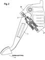
- the pedal travel simulator 2 is arranged between a vehicle-fixed component of the pedal unit, the so-called pedal bracket 27, and the brake pedal 1 or a coaxial with the brake pedal 1 rotatable member 26 in the form of a lever. Basically, it is possible with appropriate space conditions to direct the pedal travel simulator 2 on the pedal bracket 27 and the brake pedal 1 directly.
- a vehicle-mounted component may also be a component use, which is not part of the pedal unit.
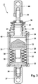
- Fig. 2 shows a simplified schematic side view of the arrangement of the pedal travel simulator 2 of a first embodiment, which in Fig. 3 is shown enlarged.
- the pedal travel simulator 2 of the first embodiment has a substantially sleeve-shaped housing 28, in which a first, the simulator element 15 supporting disc-shaped actuator 29 is slidably disposed.
- a first, the simulator element 15 supporting disc-shaped actuator 29 is slidably disposed.
- One on an inner wall 30 of the housing 28 provided stop 31 limits the movement of the actuating element 29, which is held by a provided as a spring assembly, biased spring element 32 to the stop 31.
- the prestressed spring element can be replaced in the context of the invention by any other spring element which is compressible from a predetermined applied to the brake pedal 1 foot force. It is conceivable, for example, as a spring element, an elastomer or a combination of springs.
- the spring assembly 32 which has several series-connected disc springs in this embodiment, is supported at its end on a second actuating element 33, which has a hollow cylindrical projection 35 for guiding a centrally disposed, cylindrical extension 34 of the first actuating element 29.
- a threaded extension 36 is integrally formed on the second actuating element 33, which can be screwed into a fastening element 37.
- a return spring 16 which serves to position the brake pedal 1 and to provide a response force, is supported in this embodiment on a collar 38 of the housing 28 and on a stop 39.
- FIG. 3 the pedal travel simulator 2 on another, third actuator 40, to which the simulator element 15 is pressed.
- a cylindrical extension 41 of the third actuating element 40 is connected by means of a connecting element 42 with a threaded rod 43 connected, which can be screwed to attach the pedal travel simulator 2 to the lever 26 in a fastener 44.
- the stop 39 of the return spring 16 is provided fixed to the connecting element 42.
- Fig. 7 shown characteristic of the brake system which is explained in more detail below, is almost the same in the "brake-by-wire" operation and in the fallback level.
- a force component of the brake booster 3 has to be added, which advantageously decouples the feedback to the driver in certain operating modes.
- Such brake booster are known for example as a mechanical brake assist.
- the characteristic in the fallback level is in Fig. 7 shown in dashed lines.
- Fig. 4 shows a simplified schematic front view of the arrangement of the pedal travel simulator 2 of the first embodiment. It can be seen that the pedal travel simulator 2 is arranged outside the brake pedal 1 and the pedal bracket 27. Advantageously, the pedal travel simulator 2 can also be provided within the pedal bracket 27, so that the installation space of the entire pedal unit can be further reduced. Furthermore, it is also conceivable to direct the pedal travel simulator 2 directly to the brake pedal 1.
- a further return spring 45 can be provided, which is not arranged directly on the pedal travel simulator 2. In principle, it is also possible to omit the return spring 16, so that the return spring 45 assumes the function with respect to the response and the restoring force entirely.
- Fig. 5 and 6 each show a sectional view of a pedal travel simulator 2 of a second and a third embodiment, whose function is similar to the first embodiment. In the following, only the design differences will be discussed. Identical components are provided with the same reference numerals.
- the return spring 16 is provided in a housing 46 of the pedal travel simulator 2.
- the simulator element 15 supporting, substantially disc-shaped actuator 47 with a second actuator 48 and the spring assembly 32nd provided as a tethered unit, which advantageously represents a pre-assembled assembly.
- the first actuator 47 has a cylindrical extension 49, which projects through an opening of the second actuating element 48 and is held therein by means of a fastening ring 50.
- the second actuating element 48 and thus also the spring assembly 32 and the first actuating element 47 are displaced by means of a further actuating element 51, which is connected by a threaded rod 43 to the connecting element 42 described for the first exemplary embodiment.
- the restoring spring 16 is supported between a collar 53 formed on the first actuating element 47 and a side wall 52 of the housing 46.
- Fig. 5 it can be seen that the actuator 51 is fixed thereto by deformed tabs 54 of the second actuator 48. By means of a stop 55, the tethered unit and the return spring 16 are held captive in the housing 46.
- a fastening element 56 is attached to an outer side of the side wall 52, for example by welding.
- the second exemplary embodiment differs from the first one in that, when actuated, the complete tethered structural unit comprising the first and the second actuating element 47, 48 as well as the spring assembly 32 moved against the spring force of the return spring 16 in the direction of side wall 52.
- the return spring 16 and the spring assembly 32 are connected directly in series in this embodiment. This eliminates the need for a third actuator and the structure of the pedal travel simulator 2 can be simplified.
- a pedal travel simulator 2 which additionally has a displacement sensor 57.
- This comprises a permanent magnet 58 as a signal transmitter and a sensor element 59 arranged on the housing 56 Fig. 6 it can be seen, the permanent magnet 58 is held between a member 60 and a stop disc 61 attached thereto.
- Other sensor types may also be used for this function within the scope of the invention.
- the element 60 and a second actuator 62 are positively connected to each other as parts of the bound spring package unit.
- the Fig. 8 to 13 is a further, fourth embodiment can be seen.
- Fig. 11 shows the essential structure of the pedal travel simulator 2, which has a first, the simulator element 15 supporting, stepped and sleeve-shaped actuator 63.
- a first stage 64 serves firstly to receive the simulator element 15 and secondly to abut a pretensioned spring element 65 which fulfills the same function as the spring element 32 described above Fig. 11
- the spring element 65 in this embodiment comprises two helical compression springs 66, 67, which abut against a second, stepped, disk-shaped actuating element 68.
- the two actuating elements 63 and 68 are provided by means of a shank 69, wherein the bias of the spring element 65 holds the actuating elements 63, 68 on stops 70, 71 of the shaft 69.
- the stop 70 is integrally formed on the shaft 69 and engages for positioning in a smallest step 72 of the second actuating element 68 a.
- steps 73,74 serve to position the two compression spring ends.
- a second and a third stage 75,76 of the first actuating element 63 are formed such that the first actuating element 63 is supported on the stop 71 by the bias of the spring element 65.
- the Stop 71 is held on the shaft 69 by means of a retaining ring 77 held in a groove 78 of the shaft 69.
- the two actuating elements 63 and 68 are provided with the spring element 65 and the shaft 69 as a preassembled unit.
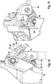
- the shaft 69 which protrudes with its threaded end 79 through a bore of the pedal bracket 27 and is fastened by means of a nut 80 to the pedal bracket 27, as from Fig. 12 can be clearly seen.
- the pedal travel simulator 2 has a third actuating element 81, on which the simulator element 15 is pressed on actuation.
- a cylindrical, threaded extension 82 of the third actuator 81 protrudes through for attachment a lug 84 of the lever 26 and is secured by a nut 83.
- a separate, formed as a leg spring return spring 85 the response is shown here via a separate, formed as a leg spring return spring 85.
- a distance a between the simulator element 15 and the third actuator 81 is adjustably provided so that the pedal characteristic is adjustable in addition to the predetermined characteristics of the spring elements of the pedal travel simulator.
- the adjustment is made by the cylindrical, threaded extension 82 of the third actuator 81 and the nut 83rd
- the end position of the brake pedal 1 is defined by a pedal end stop 86.
- FIGS. 14 and 15 show a pedal unit of a fifth embodiment. It will be discussed below only the differences from the fourth embodiment, since the remaining structure of the pedal unit is provided the same.
- a holding element 87 preferably by welding, which has a funnel-shaped receptacle 88, which is aligned in the direction of a piston rod 90 of the brake booster 3.
- This receptacle 88 serves to guide a piston rod end 89 of the piston rod 90 during assembly of the pedal unit with the brake booster 3. On the other hand, the piston rod 90 is guided after connection with the brake pedal 1 through the receptacle 88 and / or by the holding element 87.
- a damping element 91 in the form of a damping ring reduces noise when the piston rod end 89 contacts the retaining element 87.
- Another advantage here is that the brake pedal 1 is not weakened in the region of the piston rod connection.
- Fig. 16 shows a longitudinal section of a pedal unit of a sixth embodiment. This differs from the fourth exemplary embodiment in that the simulator element 15 is fastened to the pedal bracket 27 by means of a receptacle 92.
- the pedal travel simulator 2 of this embodiment has a particularly simple structure, since only one actuating element is provided.
- the distance a between the simulator element 15 and the actuating element 93 by means of the shaft 94 and provided for its attachment nuts 95 is adjustable.
- control of the pedal travel can be provided path-dependent, so that from a predetermined Actuation of the brake pedal 1 is an extension of the pedal travel and thus the pedal travel possible.
- Fig. 7 shows a force-displacement diagram of all embodiments of the brake system according to the invention. It can be seen that the characteristic increases linearly in the compression of the return spring / return springs 16,45,85 to point A. As soon as the actuating element 40, 81 or the side wall 52 is pressed against the simulator element 15, the characteristic increases progressively (points A to B). If the force applied to the brake pedal 1 foot force exceeds a predetermined by the spring force of the spring element 32,65 force F K , so the curve kinks and runs between the points B and C with a much flatter gradient than on the section A to B.
Landscapes
- Engineering & Computer Science (AREA)
- Transportation (AREA)
- Mechanical Engineering (AREA)
- Physics & Mathematics (AREA)
- Fluid Mechanics (AREA)
- Braking Elements And Transmission Devices (AREA)
- Regulating Braking Force (AREA)
Claims (19)
- Système de freinage du type "frein à commande électrique par câble" pour un véhicule automobile, comprenanta) un générateur de pression de freinage (3, 4) pouvant être actionné au moyen d'une pédale de frein (1) d'une unité de pédale, qui peut être raccordé, en dehors du mode de fonctionnement de freinage à commande électrique par câble, aux freins de roues du véhicule,b) une source de pression (3, 4, 5) pouvant être commandée au moyen d'une unité de commande électronique (7), qui, dans le mode de fonctionnement de freinage à commande électrique par câble, peut être raccordée aux freins de roues du véhicule,c) des moyens (6) pour détecter un souhait de ralentissement du conducteur etd) un simulateur de course de pédale (2) coopérant avec la pédale de frein (1), qui est formé par au moins un élément de simulateur (15) et par le biais duquel, dans le mode de fonctionnement de freinage à commande électrique par câble, une force de rappel agissant sur la pédale de frein (1) peut être simulée indépendamment de la commande de la source de pression (3, 4, 5),caractérisé en ce qu'une caractéristique force-course du simulateur de course de pédale (2) est prévue de manière commandable.
- Système de freinage selon la revendication 1, caractérisé en ce que la commande de la caractéristique force-course du simulateur de course de pédale (2) est prévue en fonction de la force, de sorte qu'à partir d'une force du pied prédéterminée appliquée sur la pédale de frein (1), un prolongement de la course de pédale soit possible et que la force de réaction à appliquer dans ce cas ne dépasse pas une valeur limite définie.
- Système de freinage selon la revendication 1 ou 2, caractérisé en ce que le simulateur de course de pédale (2) est articulé à un composant (27) fixé au véhicule et à la pédale de frein (1).
- Système de freinage selon la revendication 1 ou 2, caractérisé en ce que le simulateur de course de pédale (2) est disposé entre un composant (27) fixé au véhicule et un composant (26) pouvant tourner coaxialement par rapport à la pédale de frein (1).
- Système de freinage selon la revendication 3 ou 4, caractérisé en ce que le composant (27) fixé au véhicule fait partie de l'unité de pédale.
- Système de freinage selon l'une quelconque des revendications précédentes 2 à 5, caractérisé en ce que pour le prolongement de la course de pédale, il est prévu un élément de ressort (32, 65) qui peut être comprimé à partir d'une force du pied prédéterminée appliquée sur la pédale de frein (1) et permet ainsi un prolongement de la course de pédale.
- Système de freinage selon la revendication 6, caractérisé en ce que l'élément de ressort (32, 65) est prévu sous la forme d'un ou de plusieurs ressorts précontraints.
- Système de freinage selon la revendication 7, caractérisé en ce que l'élément de ressort précontraint (32, 65) est prévu sous la forme d'un paquet de ressorts constitué de ressorts Belleville ou sous forme d'au moins un ressort de compression à boudin (66, 67).
- Système de freinage selon la revendication 6, caractérisé en ce que l'élément de ressort est prévu sous forme d'un élastomère.
- Système de freinage selon l'une quelconque des revendications 7 à 9, caractérisé en ce que l'élément de ressort (32, 65) est disposé entre un premier élément d'actionnement (29, 47, 63) portant l'élément de simulateur (15) et un deuxième élément d'actionnement (33, 48, 62, 68).
- Système de freinage selon la revendication 10, caractérisé en ce que l'élément de ressort (32, 65) est disposé de manière attachée entre le premier élément d'actionnement (47, 63) et le deuxième élément d'actionnement (48, 62, 68).
- Système de freinage selon l'une quelconque des revendications 10 ou 11, caractérisé en ce qu'un troisième élément d'actionnement (40, 81) est prévu, contre lequel est pressé l'élément de simulateur (15), et qui est fixé de manière directe ou indirecte à la pédale de frein (1) ou au composant (26) déplaçable coaxialement par rapport à la pédale de frein.
- Système de freinage selon l'une quelconque des revendications 7 à 9, caractérisé en ce que l'élément de ressort (65) est disposé entre le composant (26) pouvant tourner coaxialement par rapport à la pédale de frein (1) et un élément d'actionnement (93), et l'élément de simulateur (15) est fixé au moyen d'un logement (92) sur le composant (27) fixé au véhicule.
- Système de freinage selon la revendication 12 ou 13, caractérisé en ce qu'une distance (a) entre l'élément de simulateur (15) et l'élément d'actionnement (81, 93) est prévue de manière ajustable.
- Système de freinage selon la revendication 10 ou 11, caractérisé en ce que le deuxième élément d'actionnement (48, 62) est fixé de manière indirecte à la pédale de frein (1) ou au composant (26) déplaçable coaxialement par rapport à la pédale de frein (1), et l'élément de simulateur (15) est pressé contre une paroi latérale (52) d'un boîtier (46) du simulateur de course de pédale (2), l'élément de ressort (32) étant disposé en alignement avec un ressort de rappel (16) de la pédale de frein (1).
- Système de freinage selon l'une quelconque des revendications précédentes, caractérisé en ce que le simulateur de course de pédale (2) présente un capteur de course (57).
- Système de freinage selon la revendication 16, caractérisé en ce que le capteur de course (57) comprend un aimant permanent (58) en tant que générateur de signal et un élément de capteur (59).
- Système de freinage selon l'une quelconque des revendications précédentes, caractérisé en ce qu'un ressort de rappel (16, 45, 85) de la pédale de frein (1) est prévu au niveau du simulateur de course de pédale (2) et/ou en tant qu'élément de ressort séparé.
- Système de freinage selon l'une quelconque des revendications précédentes, caractérisé en ce qu'un élément de retenue (87) est fixé sur la pédale de frein (1), lequel présente un logement en forme d'entonnoir (88) qui est orienté dans la direction d'une tige de piston (90) de l'amplificateur de la force de freinage (3).
Applications Claiming Priority (3)
| Application Number | Priority Date | Filing Date | Title |
|---|---|---|---|
| DE102009000235 | 2009-01-15 | ||
| DE102009002885 | 2009-05-07 | ||
| PCT/EP2010/050368 WO2010081840A1 (fr) | 2009-01-15 | 2010-01-14 | Système de freinage de type "frein à commande électrique" |
Publications (2)
| Publication Number | Publication Date |
|---|---|
| EP2387521A1 EP2387521A1 (fr) | 2011-11-23 |
| EP2387521B1 true EP2387521B1 (fr) | 2019-07-17 |
Family
ID=42142735
Family Applications (1)
| Application Number | Title | Priority Date | Filing Date |
|---|---|---|---|
| EP10700252.9A Active EP2387521B1 (fr) | 2009-01-15 | 2010-01-14 | Système de freinage de type "frein à commande électrique" |
Country Status (4)
| Country | Link |
|---|---|
| US (1) | US9079570B2 (fr) |
| EP (1) | EP2387521B1 (fr) |
| DE (1) | DE102010000882A1 (fr) |
| WO (1) | WO2010081840A1 (fr) |
Cited By (2)
| Publication number | Priority date | Publication date | Assignee | Title |
|---|---|---|---|---|
| US20220314939A1 (en) * | 2021-04-02 | 2022-10-06 | Cts Corporation | Vehicle brake pedal with linear pedal resistance and rotary dampener/position sensor assemblies |
| WO2024260853A1 (fr) * | 2023-06-19 | 2024-12-26 | Robert Bosch Gmbh | Agencement de pédale |
Families Citing this family (49)
| Publication number | Priority date | Publication date | Assignee | Title |
|---|---|---|---|---|
| JP2008222028A (ja) * | 2007-03-13 | 2008-09-25 | Honda Motor Co Ltd | シリンダ機構 |
| DE102010031372A1 (de) * | 2010-07-15 | 2012-01-19 | Zf Friedrichshafen Ag | Fußhebelwerk mit Elastomerlager |
| DE102011001365A1 (de) * | 2011-03-17 | 2012-09-20 | Dr. Ing. H.C. F. Porsche Aktiengesellschaft | Bremsvorrichtung und Bremsverfahren für ein Kraftfahrzeug |
| DE102012210434A1 (de) * | 2011-07-29 | 2013-01-31 | Continental Teves Ag & Co. Ohg | Verfahren zum Betrieb einer Bremsanlage für Kraftfahrzeuge sowie Bremsanlage |
| DE102012016259A1 (de) * | 2012-08-16 | 2014-02-20 | GM Global Technology Operations, LLC (n.d. Ges. d. Staates Delaware) | Rückstellkraftgeber für ein Kupplungssystem |
| KR101417376B1 (ko) * | 2012-10-26 | 2014-07-08 | 현대자동차주식회사 | 다단 직렬형 스프링을 이용한 페달 시뮬레이터 |
| KR101402538B1 (ko) * | 2012-11-19 | 2014-06-02 | 주식회사 만도 | 페달 시뮬레이터 |
| DE102015204232A1 (de) * | 2014-03-14 | 2015-09-17 | Schaeffler Technologies AG & Co. KG | Pedalkrafterzeugungsvorrichtung |
| US10112587B2 (en) | 2015-12-18 | 2018-10-30 | Hyster-Yale Group, Inc. | Electronic braking system |
| DE102016208942A1 (de) * | 2016-05-24 | 2017-11-30 | Robert Bosch Gmbh | Pedalkraftsimulatoreinrichtung, Fahrzeug |
| US10166954B2 (en) * | 2016-06-30 | 2019-01-01 | GM Global Technology Operations LLC | Brake-by-wire system for a vehicle with an adjustable brake pedal emulator assembly |
| DE102016212352A1 (de) * | 2016-07-06 | 2018-01-11 | Zf Friedrichshafen Ag | Pedalkraftsimulationsanordnung sowie Kraftfahrzeug |
| US10579089B2 (en) * | 2016-08-02 | 2020-03-03 | Barnes Group Inc. | Modular non-linear spring system |
| US20180093648A1 (en) * | 2016-09-30 | 2018-04-05 | GM Global Technology Operations LLC | Brake pedal emulator of a brake-by-wire system |
| DE102016222567A1 (de) * | 2016-11-16 | 2018-05-17 | Robert Bosch Gmbh | Pedalwegsimulator und Hydraulikblock mit einem Pedalwegsimulator |
| US10239531B2 (en) * | 2017-01-10 | 2019-03-26 | GM Global Technology Operations LLC | Fault-tolerant automotive braking system |
| DE102017002770A1 (de) * | 2017-03-22 | 2018-09-27 | Lucas Automotive Gmbh | Pedalsimulationsvorrichtung mit mehreren Rückstellelementen |
| JP2019132754A (ja) * | 2018-02-01 | 2019-08-08 | アイシン精機株式会社 | センサユニット |
| DE102019101646A1 (de) * | 2019-01-23 | 2020-07-23 | HELLA GmbH & Co. KGaA | Pedalemulator für ein Fahrzeug |
| CN113825682B (zh) * | 2019-05-09 | 2024-07-12 | Cts公司 | 具有踏板阻力组件和力/位置传感器的车辆制动踏板 |
| DE112020002307T5 (de) | 2019-05-09 | 2022-02-17 | Cts Corporation | Fahrzeugbremspedal mit pedalwiderstandsbaugruppe und kraft-/positionssensor |
| DE102019114199A1 (de) * | 2019-05-27 | 2020-12-03 | Methode Electronics Malta Ltd. | Vorrichtung für einen Kraft-Weg-Emulator eines Bremspedals mit einem Kraft- und Wegsensor und entsprechendes Verfahren |
| DE102019004525B4 (de) | 2019-07-01 | 2024-06-13 | Ford Global Technologies, Llc | Pedaleinheit für ein Kraftfahrzeug |
| DE102019213886A1 (de) * | 2019-09-11 | 2021-03-11 | Continental Teves Ag & Co. Ohg | Bremsanlage für Kraftfahrzeuge mit ESC-Modul und Bremskraftverstärker |
| DE102019126693A1 (de) * | 2019-10-02 | 2021-04-08 | Zf Active Safety Gmbh | Krafteingangsglied für eine Bremsbetätigungseinrichtung |
| DE102020201968A1 (de) * | 2020-02-18 | 2021-08-19 | Robert Bosch Gesellschaft mit beschränkter Haftung | Pedalwegsimulator |
| DE102020211085B4 (de) | 2020-09-02 | 2022-07-28 | Volkswagen Aktiengesellschaft | Bremspedalsystem mit einem Bremskraftsimulator, Brake-by-Wire-Bremssystem sowie Kraftfahrzeug |
| DE102020211084B4 (de) | 2020-09-02 | 2025-07-10 | Volkswagen Aktiengesellschaft | Vorrichtung zur Erzeugung einer Gegenkraft auf ein Bremspedal und Kraftfahrzeug |
| CN112277910A (zh) * | 2020-11-09 | 2021-01-29 | 苏州海之博电子科技有限公司 | 一种应用于踏板模拟机构内的多级弹性组件 |
| CN116917172A (zh) | 2021-01-13 | 2023-10-20 | Cts公司 | 车辆踏板阻力阻尼组件 |
| DE102021106461A1 (de) | 2021-03-17 | 2022-09-22 | Audi Aktiengesellschaft | Bremssystem in einem Fahrzeug |
| CN112849108A (zh) * | 2021-03-23 | 2021-05-28 | 深圳市卡妙思电子科技有限公司 | 一种模拟汽车制动踏板力反馈的装置 |
| US11661046B2 (en) | 2021-04-16 | 2023-05-30 | Bwi (Shanghai) Co., Ltd | Pedal feel emulator assembly and a brake system including the pedal feel emulator assembly |
| DE102021119441A1 (de) | 2021-07-27 | 2023-02-02 | Zf Active Safety Gmbh | Bremspedalmodul |
| DE102021119443A1 (de) * | 2021-07-27 | 2023-02-02 | Zf Active Safety Gmbh | Bremspedalmodul |
| DE102021119504A1 (de) | 2021-07-28 | 2023-02-02 | Bayerische Motoren Werke Aktiengesellschaft | Betätigungseinrichtung einer Brake-by-Wire Bremsenvorrichtung eines Kraftfahrzeugs, insbesondere eines Neigefahrzeugs |
| DE102021124879A1 (de) | 2021-09-27 | 2023-03-30 | HELLA GmbH & Co. KGaA | Pedalemulator für ein Fahrzeug |
| DE102021124880A1 (de) * | 2021-09-27 | 2023-03-30 | HELLA GmbH & Co. KGaA | Pedalemulator für ein Fahrzeug |
| JP2024536452A (ja) | 2021-10-11 | 2024-10-04 | シーティーエス・コーポレーション | 位置センサーを備えた車両ペダルバネ抵抗エミュレータアセンブリ |
| US20230258519A1 (en) | 2022-02-14 | 2023-08-17 | KSR IP Holdings, LLC | Pedal assembly having force sensing |
| DE102022204058A1 (de) | 2022-04-27 | 2023-11-02 | Continental Automotive Technologies GmbH | Federbein für ein Bremspedal und Bremspedalanordnung |
| IT202200017688A1 (it) * | 2022-08-29 | 2024-02-29 | Brembo Spa | Dispositivo simulatore di sensazione di frenata |
| WO2024050093A2 (fr) | 2022-09-02 | 2024-03-07 | KSR IP Holdings, LLC | Ensembles d'émulateur de force de pédale passive |
| US12090980B2 (en) | 2022-09-06 | 2024-09-17 | Cts Corporation | Brake pedal emulator |
| CN116353556A (zh) * | 2023-01-13 | 2023-06-30 | 重庆长安汽车股份有限公司 | 一种集成式踏板模拟器总成、制动系统及车辆 |
| DE102023205269A1 (de) * | 2023-06-06 | 2024-12-12 | Continental Automotive Technologies GmbH | Mechanisch entkoppelte Bremsbetätigungsvorrichtung für ein Kraftfahrzeug |
| DE102023205286A1 (de) * | 2023-06-06 | 2024-12-12 | Continental Automotive Technologies GmbH | Mechanisch entkoppelte Bremsbetätigungsvorrichtung für ein Kraftfahrzeug |
| DE102023205278A1 (de) * | 2023-06-06 | 2024-12-12 | Continental Automotive Technologies GmbH | Mechanisch entkoppelte Bremsbetätigungsvorrichtung für ein Kraftfahrzeug |
| DE102024000644B4 (de) | 2024-02-27 | 2025-12-24 | Mercedes-Benz Group AG | Bremspedalanordnung für ein elektronisch gesteuertes Bremssystem eines Kraftfahrzeugs und Kraftfahrzeug |
Family Cites Families (28)
| Publication number | Priority date | Publication date | Assignee | Title |
|---|---|---|---|---|
| DE69515875T2 (de) | 1995-10-11 | 2000-07-20 | Lucas Industries Ltd., London | Bremspedal für Betätigung eines Kraftfahzeugbremszylinders und eine Betätigungseinheit für eine elektronische Kraftfahzeugbremsanlage unter Verwendung des Bremspedals |
| JP4449898B2 (ja) * | 1998-04-14 | 2010-04-14 | トヨタ自動車株式会社 | フルードレス型ブレーキ操作ストローク発生装置 |
| DE19852399A1 (de) * | 1998-11-13 | 2000-05-18 | Wabco Gmbh & Co Ohg | Bremswertgeber mit integrierter Additionsredundanz |
| US6367886B1 (en) * | 2000-07-27 | 2002-04-09 | Delphi Technologies, Inc. | Brake pedal emulator system and method |
| US6464306B2 (en) * | 2001-02-27 | 2002-10-15 | Delphi Technologies, Inc. | Brake pedal feel emulator with integral force and travel sensors |
| JP2002293229A (ja) * | 2001-03-29 | 2002-10-09 | Aisin Seiki Co Ltd | ストロークシミュレータ装置及び車両用液圧ブレーキ装置 |
| JP2003261014A (ja) * | 2002-03-08 | 2003-09-16 | Hitachi Unisia Automotive Ltd | ブレーキ操作ストローク発生装置 |
| DE10230865A1 (de) * | 2002-07-09 | 2004-02-05 | Continental Teves Ag & Co. Ohg | Bremsbetätigung mit einem pneumatischen Verstärker und einem elektrisch angetriebenen Simulator |
| EP1521696B1 (fr) | 2002-07-09 | 2006-12-27 | Continental Teves AG & Co. oHG | Dispositif d'actionnement de frein a commande electrique |
| DE10358321B4 (de) | 2002-12-13 | 2020-08-27 | Zf Active Safety Gmbh | Hydraulische Pedalsimulationsvorrichtung |
| JP2004276666A (ja) * | 2003-03-13 | 2004-10-07 | Advics:Kk | ストロークシミュレータ |
| JP4254336B2 (ja) * | 2003-05-09 | 2009-04-15 | 日産自動車株式会社 | ブレーキ装置のストロークシミュレータ |
| DE102004011622A1 (de) | 2003-08-06 | 2005-03-31 | Continental Teves Ag & Co. Ohg | Bremsbetätigungseinheit zur Betätigung einer Kraftfahrzeugbremsanlage |
| US7357465B2 (en) * | 2004-10-04 | 2008-04-15 | Continental Teves, Inc. | Brake pedal feel simulator |
| DE102005017958A1 (de) * | 2004-10-15 | 2006-04-27 | Continental Teves Ag & Co. Ohg | Bremsanlage für Kraftfahrzeuge |
| CN100569566C (zh) * | 2005-02-18 | 2009-12-16 | 大陆-特韦斯贸易合伙股份公司及两合公司 | 用于机动车辆的制动设备 |
| US20090090585A1 (en) * | 2005-08-02 | 2009-04-09 | Continental Teves Ag & Co. Ohg | Method of Monitoring the Operability of a Brake Actuation Unit |
| DE102007010513A1 (de) | 2006-05-19 | 2007-11-22 | Continental Teves Ag & Co. Ohg | Betätigungseinheit für eine Kraftfahrzeugbremsanlage |
| JP2008018816A (ja) * | 2006-07-12 | 2008-01-31 | Toyota Motor Corp | ブレーキ装置、ストロークシミュレータカット機構、及びストロークシミュレータカット方法 |
| DE102007016754A1 (de) | 2006-11-29 | 2008-08-21 | Continental Teves Ag & Co. Ohg | Verfahren zur Überwachung der Funktionsfähigkeit einer Bremsbetätigungseinheit |
| ATE548236T1 (de) | 2007-03-05 | 2012-03-15 | Continental Teves Ag & Co Ohg | Betätigungseinheit für eine kraftfahrzeugbremsanlage |
| JP2008222028A (ja) * | 2007-03-13 | 2008-09-25 | Honda Motor Co Ltd | シリンダ機構 |
| DE102007016975B4 (de) * | 2007-04-10 | 2024-08-01 | Bayerische Motoren Werke Aktiengesellschaft | Betätigungseinrichtung für eine elektrohydraulische Fahrzeug-Bremsanlage mit einem Pedalkraftsimulator |
| DE102007049620A1 (de) * | 2007-04-19 | 2008-10-23 | Continental Teves Ag & Co. Ohg | Bremsanlage für Kraftfahrzeuge |
| US7748792B2 (en) | 2007-06-11 | 2010-07-06 | Ford Global Technologies | Automotive braking system with master cylinder force simulator |
| US8226175B2 (en) * | 2007-08-02 | 2012-07-24 | Continental Teves Ag & Co. Ohg | Brake system of the brake-by-wire type |
| KR101058614B1 (ko) * | 2008-12-11 | 2011-08-25 | 현대모비스 주식회사 | 회생 제동 액추에이터 장치 |
| CN103415423B (zh) * | 2011-03-11 | 2016-08-17 | 本田技研工业株式会社 | 车辆用液压产生装置及车辆用制动力产生装置 |
-
2010
- 2010-01-14 EP EP10700252.9A patent/EP2387521B1/fr active Active
- 2010-01-14 WO PCT/EP2010/050368 patent/WO2010081840A1/fr not_active Ceased
- 2010-01-14 US US13/144,331 patent/US9079570B2/en active Active
- 2010-01-14 DE DE102010000882A patent/DE102010000882A1/de not_active Withdrawn
Non-Patent Citations (1)
| Title |
|---|
| None * |
Cited By (3)
| Publication number | Priority date | Publication date | Assignee | Title |
|---|---|---|---|---|
| US20220314939A1 (en) * | 2021-04-02 | 2022-10-06 | Cts Corporation | Vehicle brake pedal with linear pedal resistance and rotary dampener/position sensor assemblies |
| US12325398B2 (en) * | 2021-04-02 | 2025-06-10 | Cts Corporation | Vehicle brake pedal with linear pedal resistance and rotary dampener/position sensor assemblies |
| WO2024260853A1 (fr) * | 2023-06-19 | 2024-12-26 | Robert Bosch Gmbh | Agencement de pédale |
Also Published As
| Publication number | Publication date |
|---|---|
| EP2387521A1 (fr) | 2011-11-23 |
| US20120007419A1 (en) | 2012-01-12 |
| DE102010000882A1 (de) | 2010-07-22 |
| US9079570B2 (en) | 2015-07-14 |
| WO2010081840A1 (fr) | 2010-07-22 |
Similar Documents
| Publication | Publication Date | Title |
|---|---|---|
| WO2010081840A1 (fr) | Système de freinage de type "frein à commande électrique" | |
| EP2183132B1 (fr) | Système de freinage de type "brake-by-wire" | |
| EP2379388B1 (fr) | Servofrein electromechanique | |
| DE102004011622A1 (de) | Bremsbetätigungseinheit zur Betätigung einer Kraftfahrzeugbremsanlage | |
| WO2012059175A1 (fr) | Dispositif d'actionnement, en particulier pour un système de freinage de véhicule | |
| DE102012000258A1 (de) | Wegsimulatorvorrichtung | |
| EP2427355B1 (fr) | Unité d'actionnement de frein pour l'actionnement d'un système de freinage de véhicule automobile | |
| EP2635470A1 (fr) | Servofrein et son procédé de production | |
| DE102013007574A1 (de) | Betätigungseinrichtung zur Anordnung zwischen einem Bremspedal und einem Hauptbremszylinder eines Kraftfahrzeugs | |
| DE102021124879A1 (de) | Pedalemulator für ein Fahrzeug | |
| EP2132067B1 (fr) | Unité d'actionnement pour système de freinage d'automobile | |
| WO2023046450A1 (fr) | Émulateur de pédale pour un véhicule | |
| EP1654145B1 (fr) | Unite d'actionnement de frein pour actionner un systeme de freinage d'automobile | |
| EP1802498B1 (fr) | Systeme de freinage de type "freinage electronique" | |
| EP2334529B1 (fr) | Générateur de force de freinage pour un système de freinage d'un véhicule automobile, avec dispositif d'appui pour un ressort de rappel | |
| EP2093110B1 (fr) | Frein de stationnement | |
| DE102011050869A1 (de) | Betätigungsvorrichtung, insbesondere für eine Fahrzeug-Bremsanlage | |
| DE102011101655A1 (de) | Betätigungsvorrichtung, insbesondere für eine Fahrzeug-Bremsanlage | |
| DE102016215726A1 (de) | Kraftfahrzeugbremsanlage mit Lüftspielkompensation | |
| DE1262799B (de) | Servobremsgeraet fuer Fahrzeuge | |
| EP2049374B1 (fr) | Unité d'actionnement de freins destinée à l'actionnement d'un système de freinage de véhicule à moteur | |
| EP2778459A2 (fr) | Dispositif d'actionnement pour un embrayage | |
| DE102024207883A1 (de) | Bremsgerät für eine Kraftfahrzeugbremsanlage | |
| DE102005049394A1 (de) | Bremsbetätigungseinheit zur Betätigung einer Kraftfahrzeugbremsanlage | |
| DE102006015193A1 (de) | Bremsbetätigungseinheit zur Betätigung einer Kraftfahrzeugbremsanlage |
Legal Events
| Date | Code | Title | Description |
|---|---|---|---|
| PUAI | Public reference made under article 153(3) epc to a published international application that has entered the european phase |
Free format text: ORIGINAL CODE: 0009012 |
|
| 17P | Request for examination filed |
Effective date: 20110816 |
|
| AK | Designated contracting states |
Kind code of ref document: A1 Designated state(s): AT BE BG CH CY CZ DE DK EE ES FI FR GB GR HR HU IE IS IT LI LT LU LV MC MK MT NL NO PL PT RO SE SI SK SM TR |
|
| DAX | Request for extension of the european patent (deleted) | ||
| RAP1 | Party data changed (applicant data changed or rights of an application transferred) |
Owner name: CONTINENTAL TEVES AG & CO. OHG |
|
| GRAP | Despatch of communication of intention to grant a patent |
Free format text: ORIGINAL CODE: EPIDOSNIGR1 |
|
| STAA | Information on the status of an ep patent application or granted ep patent |
Free format text: STATUS: GRANT OF PATENT IS INTENDED |
|
| INTG | Intention to grant announced |
Effective date: 20190401 |
|
| GRAS | Grant fee paid |
Free format text: ORIGINAL CODE: EPIDOSNIGR3 |
|
| GRAA | (expected) grant |
Free format text: ORIGINAL CODE: 0009210 |
|
| STAA | Information on the status of an ep patent application or granted ep patent |
Free format text: STATUS: THE PATENT HAS BEEN GRANTED |
|
| AK | Designated contracting states |
Kind code of ref document: B1 Designated state(s): AT BE BG CH CY CZ DE DK EE ES FI FR GB GR HR HU IE IS IT LI LT LU LV MC MK MT NL NO PL PT RO SE SI SK SM TR |
|
| REG | Reference to a national code |
Ref country code: GB Ref legal event code: FG4D Free format text: NOT ENGLISH |
|
| REG | Reference to a national code |
Ref country code: CH Ref legal event code: EP |
|
| REG | Reference to a national code |
Ref country code: DE Ref legal event code: R096 Ref document number: 502010016137 Country of ref document: DE |
|
| REG | Reference to a national code |
Ref country code: IE Ref legal event code: FG4D Free format text: LANGUAGE OF EP DOCUMENT: GERMAN |
|
| REG | Reference to a national code |
Ref country code: AT Ref legal event code: REF Ref document number: 1155572 Country of ref document: AT Kind code of ref document: T Effective date: 20190815 |
|
| REG | Reference to a national code |
Ref country code: NL Ref legal event code: MP Effective date: 20190717 |
|
| REG | Reference to a national code |
Ref country code: LT Ref legal event code: MG4D |
|
| PG25 | Lapsed in a contracting state [announced via postgrant information from national office to epo] |
Ref country code: NL Free format text: LAPSE BECAUSE OF FAILURE TO SUBMIT A TRANSLATION OF THE DESCRIPTION OR TO PAY THE FEE WITHIN THE PRESCRIBED TIME-LIMIT Effective date: 20190717 Ref country code: PT Free format text: LAPSE BECAUSE OF FAILURE TO SUBMIT A TRANSLATION OF THE DESCRIPTION OR TO PAY THE FEE WITHIN THE PRESCRIBED TIME-LIMIT Effective date: 20191118 Ref country code: HR Free format text: LAPSE BECAUSE OF FAILURE TO SUBMIT A TRANSLATION OF THE DESCRIPTION OR TO PAY THE FEE WITHIN THE PRESCRIBED TIME-LIMIT Effective date: 20190717 Ref country code: BG Free format text: LAPSE BECAUSE OF FAILURE TO SUBMIT A TRANSLATION OF THE DESCRIPTION OR TO PAY THE FEE WITHIN THE PRESCRIBED TIME-LIMIT Effective date: 20191017 Ref country code: SE Free format text: LAPSE BECAUSE OF FAILURE TO SUBMIT A TRANSLATION OF THE DESCRIPTION OR TO PAY THE FEE WITHIN THE PRESCRIBED TIME-LIMIT Effective date: 20190717 Ref country code: LT Free format text: LAPSE BECAUSE OF FAILURE TO SUBMIT A TRANSLATION OF THE DESCRIPTION OR TO PAY THE FEE WITHIN THE PRESCRIBED TIME-LIMIT Effective date: 20190717 Ref country code: FI Free format text: LAPSE BECAUSE OF FAILURE TO SUBMIT A TRANSLATION OF THE DESCRIPTION OR TO PAY THE FEE WITHIN THE PRESCRIBED TIME-LIMIT Effective date: 20190717 Ref country code: NO Free format text: LAPSE BECAUSE OF FAILURE TO SUBMIT A TRANSLATION OF THE DESCRIPTION OR TO PAY THE FEE WITHIN THE PRESCRIBED TIME-LIMIT Effective date: 20191017 |
|
| PG25 | Lapsed in a contracting state [announced via postgrant information from national office to epo] |
Ref country code: LV Free format text: LAPSE BECAUSE OF FAILURE TO SUBMIT A TRANSLATION OF THE DESCRIPTION OR TO PAY THE FEE WITHIN THE PRESCRIBED TIME-LIMIT Effective date: 20190717 Ref country code: GR Free format text: LAPSE BECAUSE OF FAILURE TO SUBMIT A TRANSLATION OF THE DESCRIPTION OR TO PAY THE FEE WITHIN THE PRESCRIBED TIME-LIMIT Effective date: 20191018 Ref country code: IS Free format text: LAPSE BECAUSE OF FAILURE TO SUBMIT A TRANSLATION OF THE DESCRIPTION OR TO PAY THE FEE WITHIN THE PRESCRIBED TIME-LIMIT Effective date: 20191117 Ref country code: ES Free format text: LAPSE BECAUSE OF FAILURE TO SUBMIT A TRANSLATION OF THE DESCRIPTION OR TO PAY THE FEE WITHIN THE PRESCRIBED TIME-LIMIT Effective date: 20190717 |
|
| PG25 | Lapsed in a contracting state [announced via postgrant information from national office to epo] |
Ref country code: TR Free format text: LAPSE BECAUSE OF FAILURE TO SUBMIT A TRANSLATION OF THE DESCRIPTION OR TO PAY THE FEE WITHIN THE PRESCRIBED TIME-LIMIT Effective date: 20190717 |
|
| PG25 | Lapsed in a contracting state [announced via postgrant information from national office to epo] |
Ref country code: DK Free format text: LAPSE BECAUSE OF FAILURE TO SUBMIT A TRANSLATION OF THE DESCRIPTION OR TO PAY THE FEE WITHIN THE PRESCRIBED TIME-LIMIT Effective date: 20190717 Ref country code: EE Free format text: LAPSE BECAUSE OF FAILURE TO SUBMIT A TRANSLATION OF THE DESCRIPTION OR TO PAY THE FEE WITHIN THE PRESCRIBED TIME-LIMIT Effective date: 20190717 Ref country code: RO Free format text: LAPSE BECAUSE OF FAILURE TO SUBMIT A TRANSLATION OF THE DESCRIPTION OR TO PAY THE FEE WITHIN THE PRESCRIBED TIME-LIMIT Effective date: 20190717 Ref country code: IT Free format text: LAPSE BECAUSE OF FAILURE TO SUBMIT A TRANSLATION OF THE DESCRIPTION OR TO PAY THE FEE WITHIN THE PRESCRIBED TIME-LIMIT Effective date: 20190717 Ref country code: PL Free format text: LAPSE BECAUSE OF FAILURE TO SUBMIT A TRANSLATION OF THE DESCRIPTION OR TO PAY THE FEE WITHIN THE PRESCRIBED TIME-LIMIT Effective date: 20190717 |
|
| PG25 | Lapsed in a contracting state [announced via postgrant information from national office to epo] |
Ref country code: SM Free format text: LAPSE BECAUSE OF FAILURE TO SUBMIT A TRANSLATION OF THE DESCRIPTION OR TO PAY THE FEE WITHIN THE PRESCRIBED TIME-LIMIT Effective date: 20190717 Ref country code: SK Free format text: LAPSE BECAUSE OF FAILURE TO SUBMIT A TRANSLATION OF THE DESCRIPTION OR TO PAY THE FEE WITHIN THE PRESCRIBED TIME-LIMIT Effective date: 20190717 Ref country code: CZ Free format text: LAPSE BECAUSE OF FAILURE TO SUBMIT A TRANSLATION OF THE DESCRIPTION OR TO PAY THE FEE WITHIN THE PRESCRIBED TIME-LIMIT Effective date: 20190717 Ref country code: IS Free format text: LAPSE BECAUSE OF FAILURE TO SUBMIT A TRANSLATION OF THE DESCRIPTION OR TO PAY THE FEE WITHIN THE PRESCRIBED TIME-LIMIT Effective date: 20200224 |
|
| REG | Reference to a national code |
Ref country code: DE Ref legal event code: R097 Ref document number: 502010016137 Country of ref document: DE |
|
| PLBE | No opposition filed within time limit |
Free format text: ORIGINAL CODE: 0009261 |
|
| STAA | Information on the status of an ep patent application or granted ep patent |
Free format text: STATUS: NO OPPOSITION FILED WITHIN TIME LIMIT |
|
| PG2D | Information on lapse in contracting state deleted |
Ref country code: IS |
|
| 26N | No opposition filed |
Effective date: 20200603 |
|
| PG25 | Lapsed in a contracting state [announced via postgrant information from national office to epo] |
Ref country code: SI Free format text: LAPSE BECAUSE OF FAILURE TO SUBMIT A TRANSLATION OF THE DESCRIPTION OR TO PAY THE FEE WITHIN THE PRESCRIBED TIME-LIMIT Effective date: 20190717 Ref country code: MC Free format text: LAPSE BECAUSE OF FAILURE TO SUBMIT A TRANSLATION OF THE DESCRIPTION OR TO PAY THE FEE WITHIN THE PRESCRIBED TIME-LIMIT Effective date: 20190717 |
|
| REG | Reference to a national code |
Ref country code: CH Ref legal event code: PL |
|
| GBPC | Gb: european patent ceased through non-payment of renewal fee |
Effective date: 20200114 |
|
| REG | Reference to a national code |
Ref country code: BE Ref legal event code: MM Effective date: 20200131 |
|
| PG25 | Lapsed in a contracting state [announced via postgrant information from national office to epo] |
Ref country code: LU Free format text: LAPSE BECAUSE OF NON-PAYMENT OF DUE FEES Effective date: 20200114 Ref country code: FR Free format text: LAPSE BECAUSE OF NON-PAYMENT OF DUE FEES Effective date: 20200131 Ref country code: GB Free format text: LAPSE BECAUSE OF NON-PAYMENT OF DUE FEES Effective date: 20200114 |
|
| PG25 | Lapsed in a contracting state [announced via postgrant information from national office to epo] |
Ref country code: BE Free format text: LAPSE BECAUSE OF NON-PAYMENT OF DUE FEES Effective date: 20200131 Ref country code: CH Free format text: LAPSE BECAUSE OF NON-PAYMENT OF DUE FEES Effective date: 20200131 Ref country code: LI Free format text: LAPSE BECAUSE OF NON-PAYMENT OF DUE FEES Effective date: 20200131 |
|
| PG25 | Lapsed in a contracting state [announced via postgrant information from national office to epo] |
Ref country code: IE Free format text: LAPSE BECAUSE OF NON-PAYMENT OF DUE FEES Effective date: 20200114 |
|
| REG | Reference to a national code |
Ref country code: AT Ref legal event code: MM01 Ref document number: 1155572 Country of ref document: AT Kind code of ref document: T Effective date: 20200114 |
|
| PG25 | Lapsed in a contracting state [announced via postgrant information from national office to epo] |
Ref country code: AT Free format text: LAPSE BECAUSE OF NON-PAYMENT OF DUE FEES Effective date: 20200114 |
|
| PG25 | Lapsed in a contracting state [announced via postgrant information from national office to epo] |
Ref country code: MT Free format text: LAPSE BECAUSE OF FAILURE TO SUBMIT A TRANSLATION OF THE DESCRIPTION OR TO PAY THE FEE WITHIN THE PRESCRIBED TIME-LIMIT Effective date: 20190717 Ref country code: CY Free format text: LAPSE BECAUSE OF FAILURE TO SUBMIT A TRANSLATION OF THE DESCRIPTION OR TO PAY THE FEE WITHIN THE PRESCRIBED TIME-LIMIT Effective date: 20190717 |
|
| PG25 | Lapsed in a contracting state [announced via postgrant information from national office to epo] |
Ref country code: MK Free format text: LAPSE BECAUSE OF FAILURE TO SUBMIT A TRANSLATION OF THE DESCRIPTION OR TO PAY THE FEE WITHIN THE PRESCRIBED TIME-LIMIT Effective date: 20190717 |
|
| REG | Reference to a national code |
Ref country code: DE Ref legal event code: R081 Ref document number: 502010016137 Country of ref document: DE Owner name: CONTINENTAL AUTOMOTIVE TECHNOLOGIES GMBH, DE Free format text: FORMER OWNER: CONTINENTAL TEVES AG & CO. OHG, 60488 FRANKFURT, DE |
|
| REG | Reference to a national code |
Ref country code: DE Ref legal event code: R081 Ref document number: 502010016137 Country of ref document: DE Owner name: CONTINENTAL AUTOMOTIVE TECHNOLOGIES GMBH, DE Free format text: FORMER OWNER: CONTINENTAL AUTOMOTIVE TECHNOLOGIES GMBH, 30165 HANNOVER, DE |
|
| PGFP | Annual fee paid to national office [announced via postgrant information from national office to epo] |
Ref country code: DE Payment date: 20240131 Year of fee payment: 15 |
|
| REG | Reference to a national code |
Ref country code: DE Ref legal event code: R119 Ref document number: 502010016137 Country of ref document: DE |
|
| PG25 | Lapsed in a contracting state [announced via postgrant information from national office to epo] |
Ref country code: DE Free format text: LAPSE BECAUSE OF NON-PAYMENT OF DUE FEES Effective date: 20250801 |