EP2387903A1 - Fermeture à glissière - Google Patents
Fermeture à glissière Download PDFInfo
- Publication number
- EP2387903A1 EP2387903A1 EP10163380A EP10163380A EP2387903A1 EP 2387903 A1 EP2387903 A1 EP 2387903A1 EP 10163380 A EP10163380 A EP 10163380A EP 10163380 A EP10163380 A EP 10163380A EP 2387903 A1 EP2387903 A1 EP 2387903A1
- Authority
- EP
- European Patent Office
- Prior art keywords
- teeth
- slide fastener
- dummy
- row
- fastening
- Prior art date
- Legal status (The legal status is an assumption and is not a legal conclusion. Google has not performed a legal analysis and makes no representation as to the accuracy of the status listed.)
- Withdrawn
Links
- 239000000463 material Substances 0.000 claims description 5
- 230000000694 effects Effects 0.000 claims description 3
- 230000005068 transpiration Effects 0.000 claims description 2
- 230000008901 benefit Effects 0.000 description 4
- 230000009471 action Effects 0.000 description 3
- 230000008878 coupling Effects 0.000 description 3
- 238000010168 coupling process Methods 0.000 description 3
- 238000005859 coupling reaction Methods 0.000 description 3
- 239000002184 metal Substances 0.000 description 3
- 238000002372 labelling Methods 0.000 description 2
- 229920003023 plastic Polymers 0.000 description 2
- 239000004033 plastic Substances 0.000 description 2
- 239000004744 fabric Substances 0.000 description 1
- 238000000034 method Methods 0.000 description 1
- 230000004048 modification Effects 0.000 description 1
- 238000012986 modification Methods 0.000 description 1
Images

Classifications
-
- A—HUMAN NECESSITIES
- A44—HABERDASHERY; JEWELLERY
- A44B—BUTTONS, PINS, BUCKLES, SLIDE FASTENERS, OR THE LIKE
- A44B19/00—Slide fasteners
- A44B19/02—Slide fasteners with a series of separate interlocking members secured to each stringer tape
- A44B19/04—Stringers arranged edge-to-edge when fastened, e.g. abutting stringers
-
- A—HUMAN NECESSITIES
- A44—HABERDASHERY; JEWELLERY
- A44B—BUTTONS, PINS, BUCKLES, SLIDE FASTENERS, OR THE LIKE
- A44B19/00—Slide fasteners
- A44B19/24—Details
-
- Y—GENERAL TAGGING OF NEW TECHNOLOGICAL DEVELOPMENTS; GENERAL TAGGING OF CROSS-SECTIONAL TECHNOLOGIES SPANNING OVER SEVERAL SECTIONS OF THE IPC; TECHNICAL SUBJECTS COVERED BY FORMER USPC CROSS-REFERENCE ART COLLECTIONS [XRACs] AND DIGESTS
- Y10—TECHNICAL SUBJECTS COVERED BY FORMER USPC
- Y10T—TECHNICAL SUBJECTS COVERED BY FORMER US CLASSIFICATION
- Y10T24/00—Buckles, buttons, clasps, etc.
- Y10T24/25—Zipper or required component thereof
- Y10T24/2539—Interlocking surface constructed from plural elements in series
- Y10T24/2543—Interlocking surface constructed from plural elements in series with element structural feature unrelated to interlocking or securing portion
Definitions
- the invention relates to slide fasteners.
- the invention discloses a technique for personalizing or labeling a slide fastener.
- a slide fastener basically comprises: a pair of tapes, a row of teeth arranged on the edge of each tape, a top stop, a bottom stop, a slider with a pull-tab.
- the tapes are made of a fabric or plastic material; the teeth, top and bottom stop and slider are usually made of metal or plastics.
- the teeth have conjugate end parts that are able to engage and disengage each other, upon the action of the slider.
- the slide fastener is often required to bear decorative elements, a logo, a trademark or the like, for aesthetic purposes and/or for individualization of the product. This is especially required by the fashion industry for high-end slide fasteners.
- the tapes are not a convenient support for any decorative element or logo.
- the parts of a slide fastener that are suitable to bear such elements are the top and bottom stops, the slider and the pull-tab.
- a symbol, a trademark or logo can be printed or engraved in a metal stop, slider or pull-tab. No other part suitable to this purpose is available.
- the teeth in particular are too small and hence the engaged rows of teeth in a closed slide fasteners have always substantially the same appearance.
- the invention is aimed to improve the ability to individualize a slide fastener.
- the invention provides a visually distinctive element in an intermediate position of the row formed by the fastening teeth. This is accomplished by the provision of dummy teeth between two of the fastening teeth of each row of the slide fastener, in at least one intermediate position of the slide fastener.
- a slide fastener comprising a pair of tapes, a top stop, a bottom stop, a first row of fastening teeth arranged on the edge of one of said tapes and a second row of fastening teeth arranged on the edge of the other one of said tapes, the fastening teeth of the first row being able to engage and disengage the fastening teeth of the second row to close and open the slide fastener, characterized in that:
- One or more intermediate gaps according to point a) above can be provided.
- the intermediate gap may be located substantially in the middle of the slide fastener, but any position is possible.
- the position of a couple of said dummy teeth is preferably in the upper half, which means closer to the upper stop, so to be more visible when the garment is worn.
- the dummy teeth as disclosed at point b) above are meant as replacement elements that fill a gap in the respective row of fastening teeth, associated to a fastener tape. Said elements that do not need to engage each other with conjugate parts in a gear-like manner, as conventional teeth of slide fasteners do, although in some embodiments the dummy teeth may have mutually engaging parts to strengthen the slide fastener.
- the dummy teeth may preferably provide an engagement which is adapted to maintain alignment of the tapes, and to avoid the opening of the slide fastener.
- Said engagement is preferably substantially rigid at least in a transversal direction, i.e. perpendicular to the direction of the slider.
- the first and second dummy tooth arranged in one gap of the slide fastener have coupling means in the form of at least a male part and a female part providing an engagement which is substantially rigid in said transversal direction.
- the dummy teeth are larger than the teeth of the slide fastener, in the longitudinal direction of the slide fastener. Being larger than the conventional teeth, the dummy teeth are recognizable and able to individualize the fastener.
- a dummy tooth according to the invention is configured with a core portion, an upper arm portion and a lower arm portion.
- the upper arm portion in use, is outside a garment or item carrying the slide fastener, while the lower arm portion is inside.
- the upper arm portion and/or the lower arm portion may have a flat surface adapted to carry a distinctive element. For example, a logo, trademark or the like can be printed or engraved onto the upper and/or the lower arm portion. More preferably, said arm portions have end flanges to securely hold the edges of the fastener tapes.
- the distinctive feature of said dummy teeth may be achieved in any way.
- the dummy teeth may be configured to show a certain letter, number or logo when the slide fastener is closed and the two dummy teeth are facing each other.
- a distinctive element is formed in an intermediate position of the chain of the teeth, for example in the middle, which is readily visible and greatly improves the individual appearance of the slide fastener.
- a certain logo or mark can be written or formed half on one dummy tooth and half on the other, so that the logo is composed when the slide fastener closes.
- the left/right dummy teeth are shaped to form themselves a trademark or logo, e.g. a symbol or letter, when they are close together.
- the dummy teeth may be of a material and/or color other than the material of other parts of the slide fastener, namely of the engaging teeth and stops, to enhance distinctiveness.
- the left and right dummy teeth of each pair need not to be identical. In some embodiments of the invention, the two dummy teeth are different. In a preferred embodiment, the lower arm portion is made larger than the upper arm portion, in order to completely fill the gap between the fastening teeth.
- a slide fastener according to the invention for example, can be manufactured by the steps of: making fastener tapes with rows of fastening teeth, removing a selected number of fastening teeth in at least one selected position of the fastener tapes, thus forming gaps in the rows of fastening teeth, and fixing the dummy teeth to the fastener tapes, so to fill the aforesaid gaps.
- a further aspect of the invention is that the above dummy teeth are able to support additional functions.
- they may have magnetic parts to provide a tactile feeling in the operation of a metal slider, such as a variation in the force required to move the slider; they may have one or more holes to provide transpiration; they may host electrical contacts to detect certain actions such as opening of the slide fastener; they may support a light-emitting or light-reflecting element, so to provide a further distinctive effect or night visibility.
- a slide fastener according to the invention with a couple of dummy teeth with an electrical contact can be positioned close to the upper stop and used to detect opening of the slide fastener.
- the main advantage of the invention is that a novel option for individualizing or labeling a slide fastener is allowed.
- a visually distinctive effect is obtained by a singularity in the rows of fastening teeth, although the provision of the dummy teeth allow the normal operation of the slider.
- the provision of one or more couple(s) of the above dummy teeth makes possible a number of additional optional features, compared to conventional fastener.
- Another advantage is that the invention needs no significant modification of the slider, because the dummy teeth substantially restore the chain of the engaging teeth and allow a free passage of the slider. Hence, a conventional slider can be used.
- Another advantage is that the chain of teeth is not significantly weakened, in particular when the dummy teeth have engagement against opening of the slide fastener in the transversal direction.
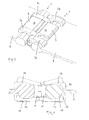
- a slide fastener as in Fig. 1 comprises a pair of tapes 1, a top stop, a bottom stop, a first row 2 of fastening teeth 3 arranged on the edge of one of tapes 1, and a second row 4 of fastening teeth 3 arranged on the edge of the other tape 1.
- the teeth of the first row 2 being able to engage and disengage the teeth of the second row 4 to close and open the slide fastener upon action of a slider 7.
- Two consecutive fastening teeth of the rows 2 and 4 are suitably spaced away, forming gaps that are filled with a first dummy tooth 5 and a second dummy tooth 6, respectively associated to tapes 1.
- the fastening teeth 3a, 3b are spaced forming a first gap in the row 2, where the dummy tooth 5 is inserted, and the fastening teeth 3c, 3d of the other row 4 are spaced forming a second gap, where the dummy tooth 6 is inserted.
- Said dummy teeth 5 and 6 are elements adapted to restore a continuity of the rows 2 and 4, in particular to allow sliding of the slider 7.
- the gap between fastening teeth 3a, 3b corresponds to removal of two fastening teeth in the row 2, between the aforesaid fastening teeth 3a and 3b.
- the gap between fastening teeth 3c, 3d of the other row 4 corresponds to removal of one tooth.
- gaps for the elements 5, 6 correspond to n fastening teeth 3 missing on one row such as row 2, and ( n+1 ) fastening teeth 3 missing on the other row such as row 4.
- the dummy teeth 5, 6 are larger than fastening teeth 3 in the longitudinal direction of the slide fastener.
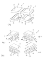
- Figs. 3 and 4 show a preferred embodiment of the dummy teeth 5 and 6.
- Each is configured with a core portion 10, 11, an upper arm portion 12, 13 and a lower arm portion 14, 15.
- the upper arm portions 12 and 13, in use, are outside a garment or item carrying the slide fastener, while the lower arm portions 14, 15 are inside.
- the upper arm portion and/or the lower arm portion have preferably flat surfaces 16 adapted to carry a distinctive element.
- a logo, trademark or the like can be printed or engraved onto a surface 16 of the upper and/or the lower arm portion.
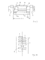
- said arm portions have end flanges 17 to securely hold the edges 18 of the fastener tapes 1, as depicted in the sectional view of Fig. 3 .
- the side edges 18 are clamped by arm portions 12, 13 and 14, 15, preferably by deformation of lower arm portions 14, 15, which are bent to hold the side egdes 18 of fastener tapes, as shown in said Fig. 3 .
- the inner face of the core portions 10, 11 of the dummy teeth 5, 6 has preferably a coupling means to prevent opening of the slide fastener in the zone of said dummy teeth, when the fastener elements 3 are missing.
- said coupling means is in the form of projecting portions 19 and 20 and recesses 21, 22.
- the core portion has also a projection 23 on the outer face, to improve the strength of connection to the fastener tapes 1, by pressing against the edges 18.
- the left and right dummy teeth 5, 6 of each couple need not to be identical in shape.
- the lower arm portion of one dummy tooth is larger than the lower arm portion of the other.
- Figs. 5 to 8 show that the dummy tooth 6 has a lower arm portion 15 which is larger than lower arm portion 14 of the dummy tooth 5.
- Said lower arm portion 15 has end parts 15A extending beyond the core portion 11, to suitably cover the space S ( Fig. 9 ) which is left between two fastening teeth 3.
- Fig. 10 shows an exemplificative embodiment where the dummy teeth 5, 6 are shaped to form a letter "H" when the slide fastener is closed.
Landscapes
- Slide Fasteners (AREA)
Priority Applications (4)
| Application Number | Priority Date | Filing Date | Title |
|---|---|---|---|
| EP10163380A EP2387903A1 (fr) | 2010-05-20 | 2010-05-20 | Fermeture à glissière |
| CN201110090460.4A CN102247037A (zh) | 2010-05-20 | 2011-04-12 | 拉链 |
| US13/106,426 US20110302749A1 (en) | 2010-05-20 | 2011-05-12 | Slide Fastener |
| JP2011113766A JP2011240144A (ja) | 2010-05-20 | 2011-05-20 | スライドファスナ |
Applications Claiming Priority (1)
| Application Number | Priority Date | Filing Date | Title |
|---|---|---|---|
| EP10163380A EP2387903A1 (fr) | 2010-05-20 | 2010-05-20 | Fermeture à glissière |
Publications (1)
| Publication Number | Publication Date |
|---|---|
| EP2387903A1 true EP2387903A1 (fr) | 2011-11-23 |
Family
ID=42744999
Family Applications (1)
| Application Number | Title | Priority Date | Filing Date |
|---|---|---|---|
| EP10163380A Withdrawn EP2387903A1 (fr) | 2010-05-20 | 2010-05-20 | Fermeture à glissière |
Country Status (4)
| Country | Link |
|---|---|
| US (1) | US20110302749A1 (fr) |
| EP (1) | EP2387903A1 (fr) |
| JP (1) | JP2011240144A (fr) |
| CN (1) | CN102247037A (fr) |
Cited By (1)
| Publication number | Priority date | Publication date | Assignee | Title |
|---|---|---|---|---|
| WO2023080883A1 (fr) * | 2021-11-08 | 2023-05-11 | Александр Павлович ПЕТРЕНКО | Fermeture éclair (variantes) |
Families Citing this family (4)
| Publication number | Priority date | Publication date | Assignee | Title |
|---|---|---|---|---|
| US10709212B1 (en) * | 2015-10-23 | 2020-07-14 | Apple Inc. | Magnetic closures |
| CN109463850B (zh) * | 2018-10-17 | 2021-06-25 | 福建浔兴拉链科技股份有限公司 | 一种多面牙拉链 |
| US12419373B2 (en) * | 2022-01-13 | 2025-09-23 | Michael Bergman | Reclosable closure |
| IT202200018486A1 (it) * | 2022-09-12 | 2024-03-12 | Ykk Corp | Elemento di cerniera lampo con una porzione porta-decorazione |
Citations (8)
| Publication number | Priority date | Publication date | Assignee | Title |
|---|---|---|---|---|
| CH200046A (de) * | 1937-12-03 | 1938-09-30 | Hans Dittmayer & Co | Reissverschluss. |
| EP0299500A1 (fr) * | 1987-07-14 | 1989-01-18 | Yoshida Kogyo K.K. | Fermeture à glissière réflèchissant la lumière |
| CN2353200Y (zh) * | 1998-09-02 | 1999-12-15 | 恺升股份有限公司 | 齿面印制饰标的拉链 |
| US6453521B1 (en) * | 2001-03-08 | 2002-09-24 | Delphi Oracle Corp. | Multiple pitch zipper |
| US20090049658A1 (en) * | 2005-04-01 | 2009-02-26 | Ykk Corporation | Readily Burstable Slide Fastener |
| US20090113676A1 (en) * | 2007-11-07 | 2009-05-07 | Chung Roger C Y | Zipper |
| KR20090082525A (ko) * | 2008-01-28 | 2009-07-31 | 서동수 | 자석지퍼 |
| US20090195400A1 (en) * | 2007-10-25 | 2009-08-06 | Viktor Oreshkin | Zipper warning alarm system |
-
2010
- 2010-05-20 EP EP10163380A patent/EP2387903A1/fr not_active Withdrawn
-
2011
- 2011-04-12 CN CN201110090460.4A patent/CN102247037A/zh active Pending
- 2011-05-12 US US13/106,426 patent/US20110302749A1/en not_active Abandoned
- 2011-05-20 JP JP2011113766A patent/JP2011240144A/ja not_active Withdrawn
Patent Citations (8)
| Publication number | Priority date | Publication date | Assignee | Title |
|---|---|---|---|---|
| CH200046A (de) * | 1937-12-03 | 1938-09-30 | Hans Dittmayer & Co | Reissverschluss. |
| EP0299500A1 (fr) * | 1987-07-14 | 1989-01-18 | Yoshida Kogyo K.K. | Fermeture à glissière réflèchissant la lumière |
| CN2353200Y (zh) * | 1998-09-02 | 1999-12-15 | 恺升股份有限公司 | 齿面印制饰标的拉链 |
| US6453521B1 (en) * | 2001-03-08 | 2002-09-24 | Delphi Oracle Corp. | Multiple pitch zipper |
| US20090049658A1 (en) * | 2005-04-01 | 2009-02-26 | Ykk Corporation | Readily Burstable Slide Fastener |
| US20090195400A1 (en) * | 2007-10-25 | 2009-08-06 | Viktor Oreshkin | Zipper warning alarm system |
| US20090113676A1 (en) * | 2007-11-07 | 2009-05-07 | Chung Roger C Y | Zipper |
| KR20090082525A (ko) * | 2008-01-28 | 2009-07-31 | 서동수 | 자석지퍼 |
Cited By (1)
| Publication number | Priority date | Publication date | Assignee | Title |
|---|---|---|---|---|
| WO2023080883A1 (fr) * | 2021-11-08 | 2023-05-11 | Александр Павлович ПЕТРЕНКО | Fermeture éclair (variantes) |
Also Published As
| Publication number | Publication date |
|---|---|
| CN102247037A (zh) | 2011-11-23 |
| JP2011240144A (ja) | 2011-12-01 |
| US20110302749A1 (en) | 2011-12-15 |
Similar Documents
| Publication | Publication Date | Title |
|---|---|---|
| EP2164356B1 (fr) | Réseaux d'éléments de fixation | |
| EP2470043B1 (fr) | Fermeture à glissière avec éléments plats | |
| US20110302749A1 (en) | Slide Fastener | |
| CN102469852B (zh) | 拉链 | |
| US7788773B2 (en) | Double-sided engaging element for slide fastener | |
| CN108685291A (zh) | 具有狭槽孔柄脚的带扣 | |
| US20070209170A1 (en) | Concealed slide fastener | |
| CN103717102A (zh) | 用于滑动拉链的止码及其制造方法 | |
| JP2007236958A6 (ja) | 隠しスライドファスナー | |
| JP4726765B2 (ja) | スライドファスナー用下止 | |
| CN105266284A (zh) | 拉链和拉头 | |
| CN1167596A (zh) | 拉链 | |
| CN110037394B (zh) | 拉链牙链带 | |
| EP2793634A1 (fr) | Élément de fermeture pour une fermeture à glissière et ses procédés de fabrication | |
| TWI407925B (zh) | 具有二以上鏈齒之拉鏈 | |
| EP3791747A1 (fr) | Demi-chaîne de fermeture | |
| CN103892523A (zh) | 拉链 | |
| CN102525081B (zh) | 发夹 | |
| CN103228168A (zh) | 拉链及拉链的止部的制造方法 | |
| CN109770484B (zh) | 用于拉链的止挡件以及拉链的制造方法 | |
| US1937299A (en) | Separable fastener | |
| US2083278A (en) | Separable interlocking fastener | |
| JP2026015877A (ja) | 自己整合型スライドファスナーのスライダー | |
| TWI480002B (zh) | The method of manufacturing the zipper and zipper | |
| GB2523115A (en) | Quick release slide fastener |
Legal Events
| Date | Code | Title | Description |
|---|---|---|---|
| AK | Designated contracting states |
Kind code of ref document: A1 Designated state(s): AL AT BE BG CH CY CZ DE DK EE ES FI FR GB GR HR HU IE IS IT LI LT LU LV MC MK MT NL NO PL PT RO SE SI SK SM TR |
|
| AX | Request for extension of the european patent |
Extension state: BA ME RS |
|
| PUAI | Public reference made under article 153(3) epc to a published international application that has entered the european phase |
Free format text: ORIGINAL CODE: 0009012 |
|
| STAA | Information on the status of an ep patent application or granted ep patent |
Free format text: STATUS: THE APPLICATION IS DEEMED TO BE WITHDRAWN |
|
| 18D | Application deemed to be withdrawn |
Effective date: 20120524 |