EP2388029A1 - Pumpenanordnung - Google Patents
Pumpenanordnung Download PDFInfo
- Publication number
- EP2388029A1 EP2388029A1 EP10075202A EP10075202A EP2388029A1 EP 2388029 A1 EP2388029 A1 EP 2388029A1 EP 10075202 A EP10075202 A EP 10075202A EP 10075202 A EP10075202 A EP 10075202A EP 2388029 A1 EP2388029 A1 EP 2388029A1
- Authority
- EP
- European Patent Office
- Prior art keywords
- pump
- section
- arrangement according
- flow
- proximal
- Prior art date
- Legal status (The legal status is an assumption and is not a legal conclusion. Google has not performed a legal analysis and makes no representation as to the accuracy of the status listed.)
- Withdrawn
Links
Images



Classifications
-
- F—MECHANICAL ENGINEERING; LIGHTING; HEATING; WEAPONS; BLASTING
- F04—POSITIVE - DISPLACEMENT MACHINES FOR LIQUIDS; PUMPS FOR LIQUIDS OR ELASTIC FLUIDS
- F04F—PUMPING OF FLUID BY DIRECT CONTACT OF ANOTHER FLUID OR BY USING INERTIA OF FLUID TO BE PUMPED; SIPHONS
- F04F5/00—Jet pumps, i.e. devices in which flow is induced by pressure drop caused by velocity of another fluid flow
- F04F5/02—Jet pumps, i.e. devices in which flow is induced by pressure drop caused by velocity of another fluid flow the inducing fluid being liquid
- F04F5/10—Jet pumps, i.e. devices in which flow is induced by pressure drop caused by velocity of another fluid flow the inducing fluid being liquid displacing liquids, e.g. containing solids, or liquids and elastic fluids
-
- A—HUMAN NECESSITIES
- A61—MEDICAL OR VETERINARY SCIENCE; HYGIENE
- A61M—DEVICES FOR INTRODUCING MEDIA INTO, OR ONTO, THE BODY; DEVICES FOR TRANSDUCING BODY MEDIA OR FOR TAKING MEDIA FROM THE BODY; DEVICES FOR PRODUCING OR ENDING SLEEP OR STUPOR
- A61M60/00—Blood pumps; Devices for mechanical circulatory actuation; Balloon pumps for circulatory assistance
- A61M60/10—Location thereof with respect to the patient's body
- A61M60/122—Implantable pumps or pumping devices, i.e. the blood being pumped inside the patient's body
- A61M60/126—Implantable pumps or pumping devices, i.e. the blood being pumped inside the patient's body implantable via, into, inside, in line, branching on, or around a blood vessel
- A61M60/13—Implantable pumps or pumping devices, i.e. the blood being pumped inside the patient's body implantable via, into, inside, in line, branching on, or around a blood vessel by means of a catheter allowing explantation, e.g. catheter pumps temporarily introduced via the vascular system
-
- A—HUMAN NECESSITIES
- A61—MEDICAL OR VETERINARY SCIENCE; HYGIENE
- A61M—DEVICES FOR INTRODUCING MEDIA INTO, OR ONTO, THE BODY; DEVICES FOR TRANSDUCING BODY MEDIA OR FOR TAKING MEDIA FROM THE BODY; DEVICES FOR PRODUCING OR ENDING SLEEP OR STUPOR
- A61M60/00—Blood pumps; Devices for mechanical circulatory actuation; Balloon pumps for circulatory assistance
- A61M60/10—Location thereof with respect to the patient's body
- A61M60/122—Implantable pumps or pumping devices, i.e. the blood being pumped inside the patient's body
- A61M60/126—Implantable pumps or pumping devices, i.e. the blood being pumped inside the patient's body implantable via, into, inside, in line, branching on, or around a blood vessel
- A61M60/135—Implantable pumps or pumping devices, i.e. the blood being pumped inside the patient's body implantable via, into, inside, in line, branching on, or around a blood vessel inside a blood vessel, e.g. using grafting
-
- A—HUMAN NECESSITIES
- A61—MEDICAL OR VETERINARY SCIENCE; HYGIENE
- A61M—DEVICES FOR INTRODUCING MEDIA INTO, OR ONTO, THE BODY; DEVICES FOR TRANSDUCING BODY MEDIA OR FOR TAKING MEDIA FROM THE BODY; DEVICES FOR PRODUCING OR ENDING SLEEP OR STUPOR
- A61M60/00—Blood pumps; Devices for mechanical circulatory actuation; Balloon pumps for circulatory assistance
- A61M60/10—Location thereof with respect to the patient's body
- A61M60/122—Implantable pumps or pumping devices, i.e. the blood being pumped inside the patient's body
- A61M60/126—Implantable pumps or pumping devices, i.e. the blood being pumped inside the patient's body implantable via, into, inside, in line, branching on, or around a blood vessel
- A61M60/148—Implantable pumps or pumping devices, i.e. the blood being pumped inside the patient's body implantable via, into, inside, in line, branching on, or around a blood vessel in line with a blood vessel using resection or like techniques, e.g. permanent endovascular heart assist devices
-
- A—HUMAN NECESSITIES
- A61—MEDICAL OR VETERINARY SCIENCE; HYGIENE
- A61M—DEVICES FOR INTRODUCING MEDIA INTO, OR ONTO, THE BODY; DEVICES FOR TRANSDUCING BODY MEDIA OR FOR TAKING MEDIA FROM THE BODY; DEVICES FOR PRODUCING OR ENDING SLEEP OR STUPOR
- A61M60/00—Blood pumps; Devices for mechanical circulatory actuation; Balloon pumps for circulatory assistance
- A61M60/10—Location thereof with respect to the patient's body
- A61M60/122—Implantable pumps or pumping devices, i.e. the blood being pumped inside the patient's body
- A61M60/165—Implantable pumps or pumping devices, i.e. the blood being pumped inside the patient's body implantable in, on, or around the heart
- A61M60/17—Implantable pumps or pumping devices, i.e. the blood being pumped inside the patient's body implantable in, on, or around the heart inside a ventricle, e.g. intraventricular balloon pumps
-
- A—HUMAN NECESSITIES
- A61—MEDICAL OR VETERINARY SCIENCE; HYGIENE
- A61M—DEVICES FOR INTRODUCING MEDIA INTO, OR ONTO, THE BODY; DEVICES FOR TRANSDUCING BODY MEDIA OR FOR TAKING MEDIA FROM THE BODY; DEVICES FOR PRODUCING OR ENDING SLEEP OR STUPOR
- A61M60/00—Blood pumps; Devices for mechanical circulatory actuation; Balloon pumps for circulatory assistance
- A61M60/20—Type thereof
- A61M60/205—Non-positive displacement blood pumps
- A61M60/211—Non-positive displacement blood pumps using a jet, venturi or entrainment effect for pumping the blood
-
- A—HUMAN NECESSITIES
- A61—MEDICAL OR VETERINARY SCIENCE; HYGIENE
- A61M—DEVICES FOR INTRODUCING MEDIA INTO, OR ONTO, THE BODY; DEVICES FOR TRANSDUCING BODY MEDIA OR FOR TAKING MEDIA FROM THE BODY; DEVICES FOR PRODUCING OR ENDING SLEEP OR STUPOR
- A61M60/00—Blood pumps; Devices for mechanical circulatory actuation; Balloon pumps for circulatory assistance
- A61M60/20—Type thereof
- A61M60/205—Non-positive displacement blood pumps
- A61M60/216—Non-positive displacement blood pumps including a rotating member acting on the blood, e.g. impeller
- A61M60/237—Non-positive displacement blood pumps including a rotating member acting on the blood, e.g. impeller the blood flow through the rotating member having mainly axial components, e.g. axial flow pumps
-
- A—HUMAN NECESSITIES
- A61—MEDICAL OR VETERINARY SCIENCE; HYGIENE
- A61M—DEVICES FOR INTRODUCING MEDIA INTO, OR ONTO, THE BODY; DEVICES FOR TRANSDUCING BODY MEDIA OR FOR TAKING MEDIA FROM THE BODY; DEVICES FOR PRODUCING OR ENDING SLEEP OR STUPOR
- A61M60/00—Blood pumps; Devices for mechanical circulatory actuation; Balloon pumps for circulatory assistance
- A61M60/40—Details relating to driving
- A61M60/403—Details relating to driving for non-positive displacement blood pumps
- A61M60/405—Details relating to driving for non-positive displacement blood pumps the force acting on the blood contacting member being hydraulic or pneumatic
-
- A—HUMAN NECESSITIES
- A61—MEDICAL OR VETERINARY SCIENCE; HYGIENE
- A61M—DEVICES FOR INTRODUCING MEDIA INTO, OR ONTO, THE BODY; DEVICES FOR TRANSDUCING BODY MEDIA OR FOR TAKING MEDIA FROM THE BODY; DEVICES FOR PRODUCING OR ENDING SLEEP OR STUPOR
- A61M60/00—Blood pumps; Devices for mechanical circulatory actuation; Balloon pumps for circulatory assistance
- A61M60/40—Details relating to driving
- A61M60/403—Details relating to driving for non-positive displacement blood pumps
- A61M60/408—Details relating to driving for non-positive displacement blood pumps the force acting on the blood contacting member being mechanical, e.g. transmitted by a shaft or cable
- A61M60/411—Details relating to driving for non-positive displacement blood pumps the force acting on the blood contacting member being mechanical, e.g. transmitted by a shaft or cable generated by an electromotor
- A61M60/414—Details relating to driving for non-positive displacement blood pumps the force acting on the blood contacting member being mechanical, e.g. transmitted by a shaft or cable generated by an electromotor transmitted by a rotating cable, e.g. for blood pumps mounted on a catheter
-
- A—HUMAN NECESSITIES
- A61—MEDICAL OR VETERINARY SCIENCE; HYGIENE
- A61M—DEVICES FOR INTRODUCING MEDIA INTO, OR ONTO, THE BODY; DEVICES FOR TRANSDUCING BODY MEDIA OR FOR TAKING MEDIA FROM THE BODY; DEVICES FOR PRODUCING OR ENDING SLEEP OR STUPOR
- A61M60/00—Blood pumps; Devices for mechanical circulatory actuation; Balloon pumps for circulatory assistance
- A61M60/40—Details relating to driving
- A61M60/403—Details relating to driving for non-positive displacement blood pumps
- A61M60/408—Details relating to driving for non-positive displacement blood pumps the force acting on the blood contacting member being mechanical, e.g. transmitted by a shaft or cable
- A61M60/411—Details relating to driving for non-positive displacement blood pumps the force acting on the blood contacting member being mechanical, e.g. transmitted by a shaft or cable generated by an electromotor
- A61M60/416—Details relating to driving for non-positive displacement blood pumps the force acting on the blood contacting member being mechanical, e.g. transmitted by a shaft or cable generated by an electromotor transmitted directly by the motor rotor drive shaft
-
- A—HUMAN NECESSITIES
- A61—MEDICAL OR VETERINARY SCIENCE; HYGIENE
- A61M—DEVICES FOR INTRODUCING MEDIA INTO, OR ONTO, THE BODY; DEVICES FOR TRANSDUCING BODY MEDIA OR FOR TAKING MEDIA FROM THE BODY; DEVICES FOR PRODUCING OR ENDING SLEEP OR STUPOR
- A61M60/00—Blood pumps; Devices for mechanical circulatory actuation; Balloon pumps for circulatory assistance
- A61M60/50—Details relating to control
- A61M60/508—Electronic control means, e.g. for feedback regulation
- A61M60/577—High-frequency driving
-
- A—HUMAN NECESSITIES
- A61—MEDICAL OR VETERINARY SCIENCE; HYGIENE
- A61M—DEVICES FOR INTRODUCING MEDIA INTO, OR ONTO, THE BODY; DEVICES FOR TRANSDUCING BODY MEDIA OR FOR TAKING MEDIA FROM THE BODY; DEVICES FOR PRODUCING OR ENDING SLEEP OR STUPOR
- A61M60/00—Blood pumps; Devices for mechanical circulatory actuation; Balloon pumps for circulatory assistance
- A61M60/80—Constructional details other than related to driving
- A61M60/802—Constructional details other than related to driving of non-positive displacement blood pumps
- A61M60/81—Pump housings
-
- A—HUMAN NECESSITIES
- A61—MEDICAL OR VETERINARY SCIENCE; HYGIENE
- A61M—DEVICES FOR INTRODUCING MEDIA INTO, OR ONTO, THE BODY; DEVICES FOR TRANSDUCING BODY MEDIA OR FOR TAKING MEDIA FROM THE BODY; DEVICES FOR PRODUCING OR ENDING SLEEP OR STUPOR
- A61M60/00—Blood pumps; Devices for mechanical circulatory actuation; Balloon pumps for circulatory assistance
- A61M60/80—Constructional details other than related to driving
- A61M60/802—Constructional details other than related to driving of non-positive displacement blood pumps
- A61M60/818—Bearings
- A61M60/825—Contact bearings, e.g. ball-and-cup or pivot bearings
-
- A—HUMAN NECESSITIES
- A61—MEDICAL OR VETERINARY SCIENCE; HYGIENE
- A61M—DEVICES FOR INTRODUCING MEDIA INTO, OR ONTO, THE BODY; DEVICES FOR TRANSDUCING BODY MEDIA OR FOR TAKING MEDIA FROM THE BODY; DEVICES FOR PRODUCING OR ENDING SLEEP OR STUPOR
- A61M60/00—Blood pumps; Devices for mechanical circulatory actuation; Balloon pumps for circulatory assistance
- A61M60/80—Constructional details other than related to driving
- A61M60/855—Constructional details other than related to driving of implantable pumps or pumping devices
- A61M60/857—Implantable blood tubes
-
- F—MECHANICAL ENGINEERING; LIGHTING; HEATING; WEAPONS; BLASTING
- F04—POSITIVE - DISPLACEMENT MACHINES FOR LIQUIDS; PUMPS FOR LIQUIDS OR ELASTIC FLUIDS
- F04D—NON-POSITIVE-DISPLACEMENT PUMPS
- F04D29/00—Details, component parts, or accessories
- F04D29/02—Selection of particular materials
- F04D29/026—Selection of particular materials especially adapted for liquid pumps
-
- F—MECHANICAL ENGINEERING; LIGHTING; HEATING; WEAPONS; BLASTING
- F04—POSITIVE - DISPLACEMENT MACHINES FOR LIQUIDS; PUMPS FOR LIQUIDS OR ELASTIC FLUIDS
- F04D—NON-POSITIVE-DISPLACEMENT PUMPS
- F04D29/00—Details, component parts, or accessories
- F04D29/18—Rotors
- F04D29/181—Axial flow rotors
-
- F—MECHANICAL ENGINEERING; LIGHTING; HEATING; WEAPONS; BLASTING
- F04—POSITIVE - DISPLACEMENT MACHINES FOR LIQUIDS; PUMPS FOR LIQUIDS OR ELASTIC FLUIDS
- F04D—NON-POSITIVE-DISPLACEMENT PUMPS
- F04D29/00—Details, component parts, or accessories
- F04D29/40—Casings; Connections of working fluid
- F04D29/52—Casings; Connections of working fluid for axial pumps
- F04D29/528—Casings; Connections of working fluid for axial pumps especially adapted for liquid pumps
-
- F—MECHANICAL ENGINEERING; LIGHTING; HEATING; WEAPONS; BLASTING
- F04—POSITIVE - DISPLACEMENT MACHINES FOR LIQUIDS; PUMPS FOR LIQUIDS OR ELASTIC FLUIDS
- F04D—NON-POSITIVE-DISPLACEMENT PUMPS
- F04D3/00—Axial-flow pumps
-
- F—MECHANICAL ENGINEERING; LIGHTING; HEATING; WEAPONS; BLASTING
- F04—POSITIVE - DISPLACEMENT MACHINES FOR LIQUIDS; PUMPS FOR LIQUIDS OR ELASTIC FLUIDS
- F04D—NON-POSITIVE-DISPLACEMENT PUMPS
- F04D7/00—Pumps adapted for handling specific fluids, e.g. by selection of specific materials for pumps or pump parts
-
- A—HUMAN NECESSITIES
- A61—MEDICAL OR VETERINARY SCIENCE; HYGIENE
- A61M—DEVICES FOR INTRODUCING MEDIA INTO, OR ONTO, THE BODY; DEVICES FOR TRANSDUCING BODY MEDIA OR FOR TAKING MEDIA FROM THE BODY; DEVICES FOR PRODUCING OR ENDING SLEEP OR STUPOR
- A61M2205/00—General characteristics of the apparatus
- A61M2205/02—General characteristics of the apparatus characterised by a particular materials
-
- A—HUMAN NECESSITIES
- A61—MEDICAL OR VETERINARY SCIENCE; HYGIENE
- A61M—DEVICES FOR INTRODUCING MEDIA INTO, OR ONTO, THE BODY; DEVICES FOR TRANSDUCING BODY MEDIA OR FOR TAKING MEDIA FROM THE BODY; DEVICES FOR PRODUCING OR ENDING SLEEP OR STUPOR
- A61M2205/00—General characteristics of the apparatus
- A61M2205/04—General characteristics of the apparatus implanted
Definitions
- the invention is in the field of mechanical engineering and precision mechanics and can be used advantageously in particular in the medical field.
- the subject matter is a pump arrangement according to the preamble of claim 1.
- Such a pump arrangement is for example from the EP 2 047 872 A1 known.
- the revealed there Pump assembly includes a pump, a pump receiving sheath with a distal suction port and a proximal discharge port, wherein the pump generates in operation a motive flow from the distal suction port to the proximal outflow port.
- a flow channel extends between the suction port and the discharge port.
- the pump is arranged in a first fluid-tight and the distal suction port portion of the enclosure, which is designed as PU covering a housing.
- a second fluid-tight portion of the envelope is present, which comprises the proximal outflow opening and is designed as a discharge hose.
- the discharge hose is firmly bonded to the PU cover.
- the pump arrangement is arranged such that the pump designed as a rotor can be arranged, for example, in a heart chamber, wherein the outflow tube extends from the heart chamber into the aorta.
- All of the blood passing through outflow openings of the outflow tube into the aorta passes through the suction opening into the flow channel formed by the envelope and thereby passes through the rotor.
- the pumped through the pump flow is identical to the exiting at the outflow total flow.
- the object of the present invention is to reduce the risk of damage to the blood or the fluid transported by the pump. Particular attention should be given to the choice of materials in the medical use of the following pump arrangement (s). These should meaningfully meet the requirements of biocompatibility. In addition to the above, interactions with foreign body surfaces are the third major aspect of blood damage and have been well studied for some time.
- a further inlet opening is introduced between the first and the second section, wherein the first section and the second section are arranged relative to one another such that the inlet opening opens into the flow channel proximal to the pump.
- the further inlet opening can also be designed as an inlet channel which has its inlet opening distally or proximally to the pump or also at the level of the pump, but which opens into the flow channel only proximally of the pump.
- the suction flow is caused by the fact that the suction current creates a suction effect, as occurs with some turbine types or water jet pumps.
- a pulse is transferred by frictional or viscosity or turbulent mixing of the fluid from the motive flow to the suction flow. This creates viscous, turbulent shear stresses.
- the impulse direction of the propellant stream is transferred to particles from the pumped medium of the suction stream, which are transported to a zone downstream within the enclosure.
- the principle of a jet pump is implemented by means of the feature according to the invention, wherein the drive flow passing directly through the pump and conveyed by it carries with it a suction flow entering through the further inlet opening.
- the inlet opening extends between the first and second sections, wherein the inlet to the inlet opening may be proximal or distal to the pump, it being advantageous if the inlet is located distally of the outflow opening. Only the mouth of the inlet opening in the flow channel should be proximal to the pump, so that the suction effect, which is caused by the drive current, is well used.
- an inlet opening formed between the suction opening and the outflow opening.
- the first and second portions of the enclosure may be formed integrally or as separate components.
- the cross section of the proximal end of the first portion is smaller than the cross section of the distal end of the second portion.
- the delivery flow is concentrated on a surface of the cross section of the proximal end of the first section and, on entering the second section, may entrain further medium, which may flow in at least through accesses in the area of the remaining area of the cross section of the distal end of the second section.
- the cross section of the first section tapers towards its proximal end.
- the first portion is nozzle-shaped at its proximal end. This leads to an improvement of the efficiency and thus to an increase of the suction suction flow.
- the feature helps to effect a downsizing of the entire pump assembly.
- the distal end of the second portion and the proximal end of the first portion overlap, that is, the distal end of the second portion is more distal than the proximal end End of the first section.
- the inlet opening between the first and the second section is in each case formed from the distal end of the second section to the proximal end of the first section as an intake passage or channel-like.
- the suction flow through the suction channel preferably flows into the flow channel in the direction of the outflow opening, almost coaxially to the conveying direction of the blowing flow.
- the main axis of the intake duct which is preferably directed in the direction of the delivery flow, an impulse of the drive flow is already transmitted to the intake flow in the direction of the outflow opening. This leads to an improvement in the efficiency.
- the distal end of the second portion is more proximal than or equal to the proximal end of the first portion.
- the concentrated motive flow exiting the proximal end of the first section encounters a fluid of different pressure and different directions, such that the concentrated flow directs a fluid of higher density further into the beginning of the second section defined by the distal end of the second section flows in and fluid, which is located between the first and the second section, with it.
- the total current is greater than the blowing current passing through the pump.
- the spacing between the distal end of the second section and the proximal end of the first section is kept small so as not to cause dispersion of the flow relative to the flow outside the enclosure. The distance should be approximately from 0 to 1/4 of the Diameter of the proximal outlet opening of the first section amount.
- the second portion comprises at least a portion of a flexible material.
- a second section located between, for example, a ventricle and a blood vessel, wherein the ventricle and the blood vessel are connected by means of a rhythmically opening and closing flap, to be pressed through the flap and thus the fluid in line with the rhythmic one Movement of the flap is promoted.
- Suitable materials include, for example, PU, PE, PP, silicone or Parilene, provided that they meet the mechanical and geometric requirements as well as the requirements for biocompatibility.
- the pump arrangement has a housing accommodating the pump. This is particularly suitable when the pump is a compressible pump, which is conveyed by means of a catheter together with the housing to its place of work.
- the housing of the pump assembly gives additional stability.
- the housing can be made of nitinol, for example.
- the first portion may be formed as a casing of the housing or a coating of the housing, wherein only a portion of the housing, preferably an axial portion, must be fluid-coated or coated.
- coatings or jackets are materials such as already mentioned in the description of the second section of flexible material.
- the housing has a constriction and / or a bulge proximal to the pump.
- a constriction a taper of the cross section of the housing relative to the pump receiving portion of the housing.
- a bulge has a cross-section of the housing which is larger in relation to a constriction or in relation to the region accommodating the pump.
- the second portion may be connected to the housing.
- first and the second section are integrally connected to one another or preferably formed in one piece.
- the second section is designed as a discharge hose.
- the second section may have a support ring in the region of the inlet opening, which ensures a spacing of the first section from the second section in the region of the inlet opening, so that a suction flow flowing through the inlet opening does not lead to a surface of the second section contacting the surface the first section sucks and thus interrupts the suction flow.
- the second section is a section of flexible material, such as a discharge hose.
- the second section has a sleeve which encloses the further inlet device and / or which partially surrounds the further inlet opening.
- This can be connected as an additional special part, for example, with a flexible portion of the second section. It is advantageous if the sleeve in the working state, which is defined for example by unfolding of the pump assembly at its work in the body is dimensionally stable and thus forms a suitable resistance to a fluid, so that the suction flow is channeled through the sleeve and into the flow channel flows.
- a sleeve instead of a sleeve, another tube section or a tube can be used.
- the pump is a compressible pump, resulting in easier insertion of the pump into the bloodstream or vessel.
- the pump is an axial pump which is mounted on a rotatable shaft which drives the pump.
- the pump assembly 1 comprises an elongated catheter extending through the blood vessel 2, in which a shaft extends, which drives the pump which is provided in the pump arrangement 1 and which is designed as a rotor.
- the proximal end of the pump assembly (viewed without a catheter) is located in the blood vessel 2, whereas the distal end of the pump assembly 1, which includes the pump, is located in the ventricle 3.
- the blood vessel 2 is bounded by the vessel wall 4.
- the flap 5 which opens and closes rhythmically, limits the heart chamber 3 and allows the flow of blood from the heart chamber 3 into the blood vessel 2.
- the pump can be used in another body-own vessel to increase the delivery rate.
- the pump assembly 10 includes a pump 11 which is formed as a rotor.
- the pump 11 is rotated by means of an illustrated, but not designated wave in rotation and thus able to transport a driving current Q T.
- the pump assembly 10 includes a sheath 12 that includes a first portion 12a and a second portion 12b.
- a suction opening 13 In the first section 12a there is a suction opening 13, through which a fluid can enter the lumen of the first section 12a, sucked by the pump 11 and transported as a drive flow Q T in the direction of the outflow opening 14.
- the envelope 12 defines between the suction port 13 and the discharge port 14, the flow channel S, which in the embodiment of Fig. 2 the lumen of the first portion 12a is completely and a lumen of the second portion 12b partially.
- the first and second portions overlap.
- the overlap defines an inlet opening 15 through which the fluid may enter the flow channel S from an area outside the lumen of the first section 12a. Due to the pumped by the pump motive flow Q T occurs in the region of the proximal end of the first section 16th to a pressure drop in the range 17. This is in the Fig. 3 shown.
- the first portion 12a and the second portion 12b both include a lumen.
- the lumen of the first section 12a has a cross-sectional area A 1
- the lumen of the second section 12b has a cross-sectional area A 2 .
- the cross sections A 1 and A 2 remain the same over the entire length of the respective section; however, this is not a mandatory feature.
- FIG. 4 Another embodiment of a pump arrangement is in the Fig. 4 described.
- the pump assembly 20 is located in a blood vessel which is bounded by the vessel walls 4.
- the distal end of the pump assembly 20 is located distal to the flap 5, the proximal end being proximal to the flap 5.
- the pump assembly 20 includes a compressible rotor 21 which is mounted on the shaft 22 on one side.
- the bearing is located at the proximal end of the rotor.
- the rotor 21 is surrounded by a housing 23, which may be made of Nitinol.
- the case consists of individual nitinol threads, wires or struts that intersect each other and create a diamond pattern. The fluid can pass through the diamonds and thus reach the rotor 21.
- the housing 23 is covered with a jacket 24 fluid-tight.
- the casing 24 extends over a length L 24 , so that a driving current Q T driven by the rotor is bundled and emerges from the housing 23 at the proximal end of the casing 24 and flows in the direction of the outflow openings 29, which are arranged in a discharge hose 25 are.
- the casing 24 forms the first portion of the casing in the embodiment of the pump assembly 20, the discharge hose 25 forms the second portion of the casing.
- the distal end of the outflow tube is secured to the housing 23 and is located more distal than the proximal end of the sheath 24.
- the sheath 24 tapers from the region of the rotor 21 in the proximal direction.
- the lumen formed by the envelope 24 in the region of the rotor 21 has a cross-sectional area A 1D , which is greater than the cross-sectional area A 1P of the proximal end of the envelope 24.
- a nozzle effect is generated, which the driving current Q T according to the principle of Venturi tube accelerates, so that this at the proximal end of the envelope 24 with a higher Flow velocity flows in the direction of the outflow openings 29.
- the intake passage 26 is accessible through the inputs 27. From the Fig.
- a plurality of inputs 27 are present, wherein the inputs are designed as circular cutouts of the outflow hose in the region of its distal end. Due to the reduced pressure in the region of the exiting drive flow Q T , a suction flow Q S is drawn in through the inlet 27 and the intake duct 26 and opens into the flow duct S, which transports the entire delivery flow to the outflow openings 29.
- Proximally the inputs 27 and the outflow hose 25 is radially surrounding a support ring 28, which is dimensionally stable in the working state of the pump.
- suction of the surface of the outflow hose 25 to the enclosure 24 is prevented due to the suction flow occurring.
- the intake passage 26 thus remains open and further fluid is drawn into the flow passage S through the intake passage 26 caused by the drive flow Q T.
- the pumping arrangement 30 comprises a rotor 31 which is mounted on an axis 32 on both sides, ie distally and proximally.
- the rotor 31 is arranged in a housing 33, which is partially covered by a PU coating 34.
- the PU coating 34 extends over a length L 34 up to a proximal to the proximal end of the rotor 31 lying area.
- the housing 33 has a constriction 33a and expands proximally of the constriction 33a to a bulge 33b. In the area of the bulge 33b, the outflow hose 35 is materially connected to the housing 33.
- the bulge 33b and the constriction 33a are spaced apart along the axis 32 by a distance d which is about 0 to 1/4 of the diameter of the constriction 33a.
- the distance d is selected such that, due to the blowing current Q T exiting from the proximal end of the PU coating 34 and driven by the rotor 31, a suction flow Q S is formed by the inlet opening 36 resulting between the PU coating 34 and the outflow hose 35 is sucked.
- the leaking from the jacket drive current Q T is discharged at a pressure P 1.
- Dermaschinestrom Q T Corporation mit dem Druck P 1 überströmt. Outside the casing 34, there is a pressure P 2 which is lower than the pressure P 1 .
- a suction flow Q S is sucked into the inlet opening 36 and transported through the outflow hose to the outflow opening 39, where it is discharged under a pressure P 3 , which is greater than the pressure P 2 , as the total flow Q A.
- the total current Q A is greater than the drive current Q T.
- the inflow opening 36 nevertheless opens into the flow channel, which is defined by the flow path of the motive current. If the drive current is correspondingly high, this occurs almost directly into the outflow hose.
- the embodiment of the pump assembly 30 of Fig. 5a is in the Fig. 5b again shown schematically.
- the distal end of the PU coating 34 has a cross-sectional area A 1D , which is greater than the cross-sectional area A 1P , which is present at the proximal end of the PU coating 34.
- the cross-sectional area A 2D of the lumen of the outflow hose 35 is again greater than the cross-sectional area A 1P .
- an inlet opening 36 is defined. This in turn leads to the flow channel S.
- the pump assembly 40 includes a rotor 41 and a first portion 42a and a second portion 42b of a sheath. At the distal end of the first portion 42a is the suction port 43 which supplies fluid to the pump 41. The fluid supplied to the pump 41 is accelerated and ejected as the driving current Q T at the proximal end of the first portion 42a.
- the second section 42b is composed of a flexible region 420b, which with a compressible, rigid in the working state of the rotor, dimensionally stable sleeve 421b is connected.
- the compressible sleeve 421b is connected to the first portion 42a by means of plastic threads or wires 422b.
- the cross section tapering from the distal end of the sleeve 421b to the proximal end of the sleeve 421b, in conjunction with the driving flow Q T, causes suction flow Q S to be drawn through the inlet port 45 formed between the sleeve 421b and the first portion 42a the suction flow Q S is combined with the drive current Q T and flows out of the outflow opening 44 in the flow channel S as a total flow Q A. From the Fig. 6 is again obvious that the inlet opening 45 opens into the flow channel S.
- the pump arrangement 50 comprises a pump 51, which is designed as an axial pump with a rotor. Furthermore, a sheath 52 is present, which can be divided into a first section 52a and a second section 52b. In this case, the first and the second portion are integrally connected to each other or made in one piece.
- a suction port 53 At the distal end of the envelope 52 is a suction port 53, which supplies fluid to the rotor, so that a driving current Q T is promoted in the working state of the rotor. The drive current Q T is conveyed in the direction of the outflow opening 54.
- the envelope 52 is made in one piece, in contrast to the embodiments shown so far, in which the first section is a separate component from the second section.
- FIGS. 8a-c Based on FIGS. 8a-c to show some different geometries of entrances of the inlet openings.
- Fig. 8a is a cross section of the embodiment of Fig. 6 shown.
- the intake opening 43 can be seen with a cross-sectional area A 1P .
- the plastic threads 422b connect the sleeve 421b to the first portion 42a.
- Fig. 8b is the embodiment of Fig. 5a shown.
- the suction opening 33 can be seen, which is defined by the PU coating 34.
- the PU coating 34 defines a lumen which has a cross-sectional area A 1D in the region of the rotor.
- the axis 32 is also recognizable.
- the housing 33 Proximal to the rotor (cf. Fig. 5a ), the housing 33, which is formed by Nitinolfäden, wires or struts, tapers to a cross-sectional area A 1P , which is defined by the constriction 33 a.
- the housing 33 widens to a bulge 33b, wherein in the region of the bulge of the discharge hose 35 is connected to the housing.
- the region 36 lying between the outflow hose 35 and the PU coating 34 serves as an inlet opening for a suction flow.
- FIG. 8c is the embodiment of Fig. 4 shown.
- the cross section is shown at the level of the support ring 28.
- the lumen with the cross-sectional area A 1D defined by the casing 24 of the first section can be seen.
- the suction channel 26 Between the casing 24 and the discharge hose 25 is the suction channel 26, through which additional fluid, driven by the current flowing through the lumen of the casing 24 in the proximal direction of the drive current, is sucked.
- the outflow hose 25 has a cross-sectional area of A 2D in this area.
- the support ring 28 can be clearly seen, as well as the connecting struts 28 a, which connect the support ring with the sheath 24.
- the support ring is made up of a plurality of segments 28b which can be brought into a folded state by means of a catheter in order to insert the pump arrangement.
Landscapes
- Health & Medical Sciences (AREA)
- Engineering & Computer Science (AREA)
- Heart & Thoracic Surgery (AREA)
- Mechanical Engineering (AREA)
- Cardiology (AREA)
- Animal Behavior & Ethology (AREA)
- Veterinary Medicine (AREA)
- Public Health (AREA)
- Anesthesiology (AREA)
- Biomedical Technology (AREA)
- Hematology (AREA)
- Life Sciences & Earth Sciences (AREA)
- General Health & Medical Sciences (AREA)
- General Engineering & Computer Science (AREA)
- Vascular Medicine (AREA)
- Physics & Mathematics (AREA)
- Fluid Mechanics (AREA)
- Transplantation (AREA)
- External Artificial Organs (AREA)
Abstract
Gegenstand der vorliegenden Erfindung ist eine Pumpenanordnung (1, 10, 20, 30, 40, 50), insbesondere zum Einsatz in körpereigenen Gefäßen, mit einer Pumpe (11, 41, 51) und einer die Pumpe aufnehmenden und einen Strömungskanal (S) begrenzenden Umhüllung (12, 42, 52) mit einer distalen Ansaugöffnung (13, 43, 53) und einer proximalen Ausströmöffnung (14, 29, 39, 44, 54) zur Erzeugung eines Treibstroms mittels der Pumpe, wobei die Pumpe in einem ersten fluiddichten und die distale Ansaugöffnung aufweisenden Abschnitt (12a, 42a, 52a) angeordnet ist und ein zweiter fluiddichter Abschnitt (12b, 42b, 52b) die proximale Ausströmöffnung umfasst. Erfindungsgemäß befindet sich zwischen dem ersten und zweiten Abschnitt eine weitere zwischen der Ansaugöffnung und Ausströmöffnung gelegene Einlassöffnung (15), wobei der erste Abschnitt und der zweite Abschnitt derart zueinander angeordnet sind, dass die Einlassöffnung proximal der Pumpe in den Strömungskanal mündet.
Description
- Die Erfindung liegt auf dem Gebiet des Maschinenbaus und der Feinmechanik und ist insbesondere im medizinischen Bereich mit Vorteil einsetzbar.
- Gegenstand ist dabei eine Pumpenanordnung nach dem Oberbegriff des Anspruchs 1.
- Aus dem Stand der Technik sind zunehmend Pumpenanordnungen insbesondere zum Einsatz in körpereigenen Gefäßen bekannt. Diese können beispielsweise zur kurzfristigen Herzunterstützung eingesetzt werden, um den Herzmuskel eines Patienten nach einem kardiogenen Schock (Myokardinfarkt) zu entlasten. Hierbei wird bisweilen auf transfemoral implantierte Mikroaxialpumpen zurückgegriffen.
- Eine derartige Pumpenanordnung ist beispielsweise aus der
EP 2 047 872 A1 bekannt. Die dort offenbarte Pumpenanordnung umfasst eine Pumpe, eine die Pumpe aufnehmende Umhüllung mit einer distalen Ansaugöffnung und einer proximalen Ausströmöffnung, wobei die Pumpe im Betrieb einen Treibstrom von der distalen Ansaugöffnung zur proximalen Ausströmöffnung hin erzeugt. Zwischen der Ansaugöffnung und der Ausströmöffnung erstreckt sich somit ein Strömungskanal. Die Pumpe ist dabei in einem ersten fluiddichten und die distale Ansaugöffnung aufweisenden Abschnitt der Umhüllung, welcher als PU-Bespannung eines Gehäuses ausgebildet ist, angeordnet. Weiterhin ist ein zweiter fluiddichter Abschnitt der Umhüllung vorhanden, welcher die proximale Ausströmöffnung umfasst und als Abströmschlauch ausgebildet ist. Der Abströmschlauch wird stoffschlüssig mit der PU-Bespannung verbunden. Die Pumpenanordnung ist derart angeordnet, dass die als Rotor ausgebildete Pumpe beispielsweise in einer Herzkammer angeordnet werden kann, wobei sich der Abströmschlauch von der Herzkammer in die Aorta hinein erstreckt. - Sämtliches über Ausströmöffnungen des Abströmschlauchs in die Aorta tretende Blut gelangt durch die Ansaugöffnung in den durch die Umhüllung gebildeten Strömungskanal und passiert dabei den Rotor. Mit anderen Worten: Der durch die Pumpe geförderte Förderstrom ist identisch mit dem an der Ausströmöffnung austretenden Gesamtstrom.
- Auch die Gegenstände der Druckschriften
DE 41 24 299 A1 ,DE 10 2004 054 714 A1 ,WO 2007/112033 A2 undUS 2008/132748 A1 verfahren nach dem vorhergehend benannten Prinzip. - Da sämtliches Blut in direkten Kontakt mit der Pumpe kommt, ist bei der Herstellung der Pumpen ein besonders hoher Aufwand nötig, um die blutschädigende Wirkung der beweglichen Pumpenteile zu reduzieren. Diese blutschädigende Wirkung manifestiert sich in direkter mechanischer Scherung an beweglichen und stationären Pumpenteilen und in Scherung durch auftretende Schubspannungsfelder im Fluid während der Passage des Strömungskanals (s. o.). Daher entstehen auch Pumpengeometrien, welche nicht mittels eines minimalinvasiven Eingriffs eingesetzt werden können.
- Der vorliegenden Erfindung liegt die Aufgabe zugrunde, die Gefahr einer Schädigung des Blutes bzw. des durch die Pumpe transportierten Fluids zu verringern. Besonderes Augenmerk bei der medizinischen Verwendung der nachstehenden Pumpenanordung(en) ist auf die Wahl der Werkstoffe zu legen. Diese sollten sinnhafterweise den Ansprüchen an die Biokompatibilität genügen. Interaktionen mit Fremdkörperoberflächen bilden ergänzend zu obiger Ausführung den dritten großen Aspekt bei der Blutschädigung und werden seit geraumer Zeit hinreichend untersucht.
- Erfindungsgemäß wird zwischen dem ersten und dem zweiten Abschnitt eine weitere Einlassöffnung eingebracht, wobei der erste Abschnitt und der zweite Abschnitt derart zueinander angeordnet sind, dass die Einlassöffnung proximal der Pumpe in den Strömungskanal mündet. Hierbei kann die weitere Einlassöffnung auch als Einlasskanal ausgebildet sein, der distal bzw. proximal der Pumpe oder auch auf Höhe der Pumpe seine Einlassöffnung hat, der aber erst proximal der Pumpe in den Strömungskanal mündet.
- Mithilfe des erfindungsgemäßen Merkmals ist es möglich, dass ein die Pumpe durchlaufender Treibstrom durch den Strömungskanal an der Mündung der Einlassöffnung in Richtung der Auslassöffnung vorbeiströmt und somit gegenüber dem in der Einlassöffnung vorliegenden Fluiddruck einen Druckabfall bewirkt, welcher zu einem Nachsaugen von Fluid durch die Einlassöffnung und in den Strömungskanal führt. Hierdurch ist der an der Ausströmöffnung ausströmende Gesamtstrom größer als der die Pumpe direkt passierende und von dieser geförderte Treibstrom, da durch die Einlassöffnung ein zusätzlicher Saugstrom hinzukommt.
- Der Saugstrom entsteht dadurch, dass durch den Treibstrom eine Sogwirkung entsteht, wie sie auch bei einigen Turbinenarten oder Wasserstrahlpumpen auftritt. Bei der Sogwirkung wird ein Impuls durch Reibung oder Viskosität oder turbulente Mischung des Fluids vom Treibstrom auf den Saugstrom übertragen. Auf diese Weise entstehen viskose, turbulente Schubspannungen. Die Impulsrichtung des Treibmittelstroms wird auf Teilchen aus dem zu fördernden Medium des Saugstroms übertragen, welche in eine Zone stromabwärts innerhalb der Umhüllung transportiert werden.
- Im Wesentlichen wird mithilfe des erfindungsgemäßen Merkmals das Prinzip einer Strahlpumpe umgesetzt, wobei der die Pumpe direkt passierende und von dieser geförderte Treibstrom einen durch die weitere Einlassöffnung eintretenden Saugstrom mit sich reißt.
- Die Einlassöffnung erstreckt sich dabei zwischen dem ersten und zweiten Abschnitt, wobei der Eingang zur Einlassöffnung proximal oder distal der Pumpe liegen kann, wobei es vorteilhaft ist, wenn der Eingang distal der Ausströmöffnung liegt. Lediglich die Mündung der Einlassöffnung in den Strömungskanal sollte proximal der Pumpe liegen, so dass der Saugeffekt, welcher durch den Treibstrom verursacht wird, gut genutzt wird.
- Besonders vorteilhaft ist eine zwischen der Ansaugöffnung und der Ausströmöffnung gebildete Einlassöffnung.
- Der erste und zweite Abschnitt der Umhüllung können einstückig oder als voneinander getrennte Bauteile ausgebildet sein.
- In einer ersten Ausführungsform ist der Querschnitt des proximalen Endes des ersten Abschnitts kleiner als der Querschnitt des distalen Endes des zweiten Abschnitts. Hierdurch wird der Förderstrom auf eine Fläche des Querschnitts des proximalen Endes des ersten Abschnitts konzentriert und kann beim Eintritt in den zweiten Abschnitt weiteres Medium mit sich reißen, welches zumindest durch Zugänge im Bereich der verbleibenden Fläche des Querschnitts des distalen Endes des zweiten Abschnitts einfließen kann.
- In einer weiteren Ausführungsform verjüngt sich der Querschnitt des ersten Abschnitts zu seinem proximalen Ende hin. Durch die Verjüngung ist der erste Abschnitt an seinem proximalen Ende düsenförmig ausgebildet. Dies führt zu einer Verbesserung des Wirkungsgrades und somit zu einer Erhöhung des angesogenen Saugstromes. Zudem hilft das Merkmal, eine Verkleinerung der gesamten Pumpenanordnung zu bewirken.
- In einer weiteren Ausführungsform überlappen sich das distale Ende des zweiten Abschnitts und das proximale Ende des ersten Abschnitts, d. h., das distale Ende des zweiten Abschnitts liegt distaler als das proximale Ende des ersten Abschnitts. Dabei ist es vorteilhaft, wenn die Einlassöffnung zwischen dem ersten und dem zweiten Abschnitt jeweils vom distalen Ende des zweiten Abschnitts zum proximalen Ende des ersten Abschnitts hin als Ansaugkanal oder kanalartig ausgebildet ist. Hierdurch strömt der Saugstrom durch den Ansaugkanal vorzugsweise nahezu koaxial zur Förderrichtung des Treibstroms in den Strömungskanal in Richtung der Ausströmöffnung ein. Hierbei wird dem Saugstrom aufgrund der vorzugsweise in Richtung des Förderstroms gerichteten Hauptachse des Ansaugkanals bereits ein Impuls des Treibstroms in Richtung der Ausströmöffnung übertragen. Dies führt zu einer Verbesserung des Wirkungsgrads.
- In einer weiteren Ausführungsform befindet sich das distale Ende des zweiten Abschnitts proximaler als oder auf gleicher Höhe wie das proximale Ende des ersten Abschnitts. Durch die Beabstandung trifft der konzentrierte, aus dem proximalen Ende des ersten Abschnitts austretende Treibstrom auf ein Fluid unterschiedlichen Drucks und unterschiedlicher Richtungen, so dass der konzentrierte Förderstrom einem Fluid höherer Dichte gleich weiter in den durch das distale Ende des zweiten Abschnitts definierten Beginn des zweiten Abschnitts hineinfließt und Fluid, welches sich zwischen dem ersten und dem zweiten Abschnitt befindet, mit sich zieht. Hierdurch wird der Gesamtstrom gegenüber dem durch die Pumpe tretenden Treibstrom größer. Hierbei ist jedoch darauf zu achten, dass die Beabstandung zwischen dem distalen Ende des zweiten Abschnitts und dem proximalen Ende des ersten Abschnitts gering gehalten wird, um keine Zerstreuung des Förderstroms gegenüber dem außerhalb der Umhüllung vorliegenden Strom zu bewirken. Der Abstand sollte näherungsweise von 0 bis 1/4 des Durchmessers der proximalen Austrittsöffnung des ersten Abschnitts betragen.
- In einer weiteren Ausführungsform umfasst der zweite Abschnitt zumindest einen Teilbereich aus einem flexiblen Material. Hierdurch ist es möglich, dass ein zwischen beispielsweise einer Herzkammer und einem Blutgefäß, wobei die Herzkammer und das Blutgefäß mittels einer sich rhythmisch öffnenden und schließenden Klappe verbunden sind, liegender zweiter Abschnitt durch die Klappe eingedrückt werden kann und so das Fluid im Einklang mit der rhythmischen Bewegung der Klappe befördert wird. Als geeignete Materialien sind beispielsweise PU, PE, PP, Silikon oder Parilene geeignet, sofern sie die mechanischen und geometrischen Anforderungen sowie die Anforderungen an Biokompatibilität erfüllen.
- In einer weiteren Ausführungsform weist die Pumpenanordnung ein die Pumpe aufnehmendes Gehäuse auf. Dies ist insbesondere dann geeignet, wenn es sich bei der Pumpe um eine komprimierbare Pumpe handelt, welche mittels eines Katheters zusammen mit dem Gehäuse an ihren Arbeitsort befördert wird. Zudem verleiht das Gehäuse der Pumpenanordnung eine zusätzliche Stabilität. Das Gehäuse kann beispielsweise aus Nitinol hergestellt werden.
- Beim Vorhandensein eines Gehäuses kann der erste Abschnitt als eine Ummantelung des Gehäuses oder eine Beschichtung des Gehäuses ausgebildet sein, wobei lediglich ein Teilbereich des Gehäuses, vorzugsweise ein axialer Teilbereich, fluiddicht ummantelt bzw. beschichtet sein muss. Als Beschichtungen bzw. Ummantelungen eignen sich hier Materialien, wie sie bereits bei der Beschreibung des zweiten Abschnitts aus einem flexiblen Material aufgeführt wurden.
- In einer weiteren Ausführungsform weist das Gehäuse proximal der Pumpe eine Einschnürung und/oder eine Ausbauchung auf. Hierbei ist unter einer Einschnürung eine Verjüngung des Querschnitts des Gehäuses gegenüber dem die Pumpe aufnehmenden Bereich des Gehäuses zu verstehen. Eine Ausbauchung weist einen gegenüber einer Einschnürung oder gegenüber dem die Pumpe aufnehmenden Bereich vergrößerten Querschnitt des Gehäuses auf. Mithilfe einer derartigen Formgebung können Verjüngungen des ersten Abschnitts bzw. größere Querschnitte des zweiten Abschnitts besonders leicht und vorteilhaft realisiert werden. Auch der zweite Abschnitt kann mit dem Gehäuse verbunden sein.
- In einer weiteren Ausführungsform sind der erste und der zweite Abschnitt stoffschlüssig miteinander verbunden oder vorzugsweise einstückig ausgebildet.
- In einer weiteren Ausführungsform ist der zweite Abschnitt als ein Abströmschlauch ausgebildet.
- Weiterhin kann der zweite Abschnitt im Bereich der Einlassöffnung einen Stützring aufweisen, welcher eine Beabstandung des ersten Abschnitts vom zweiten Abschnitt im Bereich der Einlassöffnung gewährleistet, so dass ein durch die Einlassöffnung fließender Saugstrom nicht dazu führt, dass sich eine Oberfläche des zweiten Abschnitts an die Oberfläche des ersten Abschnitts saugt und somit den Saugstrom unterbricht. Dies ist insbesondere dann vorteilhaft, wenn es sich bei dem zweiten Abschnitt um einen Abschnitt aus flexiblem Material wie beispielsweise einen Abströmschlauch handelt.
- In einer weiteren Ausführungsform weist der zweite Abschnitt eine die weitere Einlassvorrichtung umfassende bzw. die weitere Einlassöffnung teilweise umfassende Hülse auf. Diese kann als zusätzliches Spezialteil beispielsweise mit einem flexiblen Bereich des zweiten Abschnitts verbunden werden. Dabei ist es vorteilhaft, wenn die Hülse im Arbeitszustand, welcher beispielsweise durch Entfaltung der Pumpenanordnung an ihrem Arbeitsort im Körper definiert ist, formfest ist und somit gegenüber einem Fluid einen geeigneten Widerstand bildet, so dass der Saugstrom durch die Hülse kanalisiert wird und in den Strömungskanal einströmt.
- Anstelle einer Hülse kann auch ein weiterer Schlauchabschnitt oder ein Rohr verwendet werden.
- In einer weiteren Ausführungsform ist die Pumpe eine komprimierbare Pumpe, was zu einem leichteren Einführen der Pumpe in die Blutbahn oder ein Gefäß führt.
- Weiterhin ist es vorteilhaft, wenn die Pumpe eine Axialpumpe ist, welche auf einer rotierbaren Welle, die die Pumpe antreibt, befestigt ist.
- Nachfolgend soll die Erfindung anhand einiger Ausführungsbeispiele genauer erläutert werden. Es zeigen:
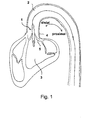
- Fig. 1
- die Verwendung einer Pumpenanordnung in einem Herzen;
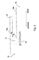
- Fig. 2
- eine schematische Darstellung einer Ausführungsform der Pumpenanordnung;
- Fig. 3
- eine schematische Darstellung einer Einlassöffnung einer Ausführungsform der Pumpenanordnung;
- Fig. 4
- eine Ausführungsform einer Pumpenanordnung;
- Fig. 5a
- eine weitere Ausführungsform einer Pumpenanordnung;
- Fig. 5b
- eine schematische Darstellung der Pumpenanordnung der
Fig. 5a ; - Fig. 6
- eine weitere Ausführungsform einer Pumpenanordnung;
- Fig. 7
- eine weitere Ausführungsform einer Pumpenanordnung;
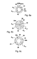
- Fign. 8a-8c
- Querschnitte durch verschiedene Pumpenanordnungen.
- In der
Fig. 1 ist eine mögliche Verwendung für die Pumpenanordnung 1 dargestellt. Die Pumpenanordnung 1 umfasst einen durch das Blutgefäß 2 reichenden länglichen Katheter, in welchem eine Welle verläuft, welche die in der Pumpenanordnung 1 vorhandene, als Rotor ausgebildete Pumpe antreibt. Das proximale Ende der Pumpenanordnung (ohne Katheter betrachtet) befindet sich im Blutgefäß 2, wohingegen das distale, die Pumpe umfassende Ende der Pumpenanordnung 1 sich in der Herzkammer 3 befindet. Das Blutgefäß 2 wird durch die Gefäßwand 4 begrenzt. Weiterhin begrenzt die Klappe 5, welche sich rhythmisch öffnet und schließt, die Herzkammer 3 und ermöglicht den Blutfluss von der Herzkammer 3 in das Blutgefäß 2. - Neben der dargestellten Verwendung einer erfindungsgemäßen Pumpenanordnung sind weitere Verwendungen möglich. So kann die Pumpe beispielsweise in einem anderen körpereigenen Gefäß zur Erhöhung der Förderleistung eingesetzt werden.
- Anhand der
Fig. 2 soll die Wirkungsweise einer erfindungsgemäßen Pumpenanordnung erläutert werden. Die Pumpenanordnung 10 umfasst eine Pumpe 11, welche als Rotor ausgebildet ist. Die Pumpe 11 wird mittels einer dargestellten, jedoch nicht bezeichneten Welle in Drehung versetzt und vermag so einen Treibstrom QT zu transportieren. Die Pumpenanordnung 10 weist eine Umhüllung 12 auf, welche einen ersten Abschnitt 12a und einen zweiten Abschnitt 12b umfasst. In dem ersten Abschnitt 12a befindet sich eine Ansaugöffnung 13, durch welche ein Fluid in das Lumen des ersten Abschnitts 12a eintreten kann, durch die Pumpe 11 angesogen und als Treibstrom QT in Richtung der Ausströmöffnung 14 transportiert wird. Die Umhüllung 12 definiert zwischen der Ansaugöffnung 13 und der Ausströmöffnung 14 den Strömungskanal S, welcher beim Ausführungsbeispiel derFig. 2 das Lumen des ersten Abschnitts 12a vollständig und ein Lumen des zweiten Abschnitts 12b teilweise umfasst. - Zwischen dem proximalen Ende des ersten Abschnitts 12a und dem distalen Ende des zweiten Abschnitts 12b überlappen sich der erste und zweite Abschnitt. Durch die Überlappung wird eine Einlassöffnung 15 definiert, durch welche das Fluid von einem Bereich außerhalb des Lumens des ersten Abschnitts 12a in den Strömungskanal S eintreten kann. Aufgrund des durch die Pumpe geförderten Treibstroms QT kommt es im Bereich des proximalen Endes des ersten Abschnitts 16 zu einem Druckabfall im Bereich 17. Dies ist in der
Fig. 3 dargestellt. - Durch den Druckabfall im Bereich 17 wird durch die Einlassöffnung 15 weiteres Fluid in Richtung der Ausströmöffnung 14 gesogen, welches als Saugstrom QS proximal des proximalen Endes des ersten Abschnitts 16 in den Strömungskanal eintritt. Somit mündet die Eingangsöffnung 15 in den Strömungskanal S.
- Der erste Abschnitt 12a und der zweite Abschnitt 12b umfassen beide ein Lumen. Dabei weist das Lumen des ersten Abschnitts 12a eine Querschnittsfläche A1 auf, das Lumen des zweiten Abschnitts 12b eine Querschnittsfläche A2. Im vorliegenden Ausführungsbeispiel bleiben die Querschnitte A1 und A2 über die gesamte Länge des jeweiligen Abschnitts gleich; dies ist jedoch kein zwingendes Merkmal. Durch den zwischen dem distalen Ende des zweiten Abschnitts 12b und dem proximalen Ende des ersten Abschnitts 12a parallel zum Treibstrom verlaufenden, als Einlassöffnung 15 ausgebildeten Kanal bekommt der Saugstrom bereits eine Impulsrichtung in Richtung der Ausströmöffnung 14. Durch den zusätzlichen Saugstrom QS ist das an der Ausströmöffnung 14 ausgeströmte Volumen pro Zeit QA größer als der die Pumpe passierende Treibstrom QT.
- Eine weitere Ausführungsform einer Pumpenanordnung ist in der
Fig. 4 beschrieben. Die Pumpenanordnung 20 befindet sich in einem Blutgefäß, welches durch die Gefäßwände 4 begrenzt wird. Das distale Ende der Pumpenanordnung 20 befindet sich distal der Klappe 5, das proximale Ende befindet sich proximal der Klappe 5. - Die Pumpenanordnung 20 umfasst einen komprimierbaren Rotor 21, welcher auf der Welle 22 einseitig befestigt ist. Die Lagerung befindet sich am proximalen Ende des Rotors. Der Rotor 21 wird durch ein Gehäuse 23 umgeben, welches aus Nitinol hergestellt sein kann. Das Gehäuse besteht aus einzelnen Nitinolfäden, -drähten oder -streben, welche sich gegenseitig kreuzen und ein Rautenmuster erzeugen. Das Fluid kann durch die Rauten hindurchtreten und so den Rotor 21 erreichen.
- Teilweise ist das Gehäuse 23 mit einer Ummantelung 24 fluiddicht abgedeckt. Dabei erstreckt sich die Ummantelung 24 über eine Länge L24, so dass ein durch den Rotor angetriebener Treibstrom QT gebündelt wird und am proximalen Ende der Ummantelung 24 aus dem Gehäuse 23 austritt und in Richtung der Ausströmöffnungen 29 fließt, welche in einem Abströmschlauch 25 angeordnet sind.
- Die Ummantelung 24 bildet bei der Ausführung der Pumpenanordnung 20 den ersten Abschnitt der Umhüllung, der Abströmschlauch 25 bildet den zweiten Abschnitt der Umhüllung. Das distale Ende des Abströmschlauchs ist am Gehäuse 23 befestigt und liegt distaler als das proximale Ende der Umhüllung 24.
- Die Umhüllung 24 verjüngt sich vom Bereich des Rotors 21 in proximaler Richtung. So weist das durch die Umhüllung 24 gebildete Lumen im Bereich des Rotors 21 eine Querschnittsfläche A1D auf, welche größer ist als die Querschnittsfläche A1P des proximalen Endes der Umhüllung 24. Hierdurch wird ein Düseneffekt erzeugt, welcher den Treibstrom QT nach dem Prinzip des Venturirohrs beschleunigt, so dass dieser am proximalen Ende der Umhüllung 24 mit einer höheren Flussgeschwindigkeit in Richtung der Ausströmöffnungen 29 strömt. Zwischen der Umhüllung 24 und dem Abströmschlauch 25 befindet sich der Ansaugkanal 26, welcher durch die Eingänge 27 zugänglich ist. Aus der
Fig. 4 ist erkennbar, dass mehrere Eingänge 27 vorhanden sind, wobei die Eingänge als kreisrunde Ausschnitte des Abströmschlauchs im Bereich seines distalen Endes ausgeführt sind. Aufgrund des im Bereich des austretenden Treibstroms QT verringerten Drucks wird ein Saugstrom QS durch den Eingang 27 und den Ansaugkanal 26 angesogen und mündet in den Strömungskanal S, welcher den gesamten Förderstrom zu den Ausströmöffnungen 29 transportiert. - Proximal der Eingänge 27 und den Abströmschlauch 25 radial umlaufend befindet sich ein Stützring 28, welcher im Arbeitszustand der Pumpe formstabil ist. So wird ein Ansaugen der Oberfläche des Abströmschlauchs 25 an die Umhüllung 24 aufgrund des auftretenden Saugstroms verhindert. Der Ansaugkanal 26 bleibt somit geöffnet, und es wird weiteres Fluid durch den Ansaugkanal 26, bewirkt durch den Treibstrom QT, in den Strömungskanal S gesogen.
- Eine weitere Ausführungsform der erfindungsgemäßen Pumpanordnung ist in der
Fig. 5a dargestellt. Die Pumpanordnung 30 umfasst einen Rotor 31, welcher auf einer Achse 32 beidseitig, d. h. distal und proximal, gelagert ist. Der Rotor 31 ist in einem Gehäuse 33 angeordnet, welches abschnittsweise durch eine PU-Beschichtung 34 ummantelt ist. Die PU-Beschichtung 34 erstreckt sich dabei über eine Länge L34 bis zu einem proximal zum proximalen Ende des Rotors 31 liegenden Bereich hin. Das Gehäuse 33 weist eine Einschnürung 33a auf und weitet sich proximal der Einschnürung 33a zu einer Ausbauchung 33b auf. Im Bereich der Ausbauchung 33b ist der Abströmschlauch 35 mit dem Gehäuse 33 stoffschlüssig verbunden. Die Ausbauchung 33b und die Einschnürung 33a sind entlang der Achse 32 gemessen um einen Abstand d voneinander beabstandet, der etwa 0 bis 1/4 des Durchmessers der Einschnürung 33a beträgt. Dabei ist der Abstand d derart gewählt, dass aufgrund des aus dem proximalen Ende der PU-Beschichtung 34 austretenden, durch den Rotor 31 getriebenen Treibstroms QT ein Saugstrom QS durch die sich zwischen der PU-Beschichtung 34 und dem Abströmschlauch 35 ergebende Eingangsöffnung 36 nachgesogen wird. Der aus der Ummantelung austretende Treibstrom QT wird mit einem Druck P1 ausgeströmt. Außerhalb der Ummantelung 34 liegt ein Druck P2 an, welcher geringer ist als der Druck P1. Durch diesen Druckunterschied wird ein Saugstrom QS in die Eingangsöffnung 36 eingesogen und durch den Abströmschlauch zu der Ausströmöffnung 39 hin transportiert, wo dieser unter einem Druck P3, welcher größer als der Druck P2 ist, als Gesamtstrom QA ausgestoßen wird. Der Gesamtstrom QA ist dabei größer als der Treibstrom QT. - Auch wenn der Strömungskanal S, welcher sich zwischen der Ansaugöffnung distal des Rotors 31 und der Ausströmöffnung 39 erstreckt, zwischen dem proximalen Ende der PU-Beschichtung 34 und dem distalen Ende des Abströmschlauchs 35 fluiddurchlässig ist, mündet die Einströmöffnung 36 dennoch in den Strömungskanal, welcher durch den Flussverlauf des Treibstroms definiert ist. Ist der Treibstrom entsprechend hoch, tritt dieser nahezu direkt in den Abströmschlauch ein.
- Durch die zusätzlich zur distal des Rotors 31 gelegenen Ansaugöffnung vorhandene Eingangsöffnung ist es möglich, dass ein Teilstrom des an der Ausströmöffnung 39 austretenden Gesamtstroms QA den Rotor 31 nicht passiert und somit keine Gefahr der Blutschädigung durch den Rotor 31 besteht.
- Die Ausführungsform der Pumpenanordnung 30 der
Fig. 5a ist in derFig. 5b nochmals schematisch dargestellt. Hier ist erkennbar, dass das distale Ende der PU-Beschichtung 34 eine Querschnittsfläche A1D aufweist, welche größer gegenüber der Querschnittsfläche A1P ist, welche am proximalen Ende der PU-Beschichtung 34 vorliegt. Somit verjüngt sich das durch die PU-Beschichtung 34 umschlossene Lumen, was eine Wirkungsgradverbesserung zur Folge hat. Die Querschnittsfläche A2D des Lumens des Abströmschlauchs 35 ist wiederum größer als die Querschnittsfläche A1P. Somit wird zumindest durch den Bereich der Querschnittsfläche A2D, welcher nach der Subtraktion der Querschnittsfläche A1P verbleibt, eine Eingangsöffnung 36 definiert. Diese mündet wiederum in den Strömungskanal S. - Eine weitere Ausführungsform einer Pumpenanordnung ist in der
Fig. 6 dargestellt. Hierbei wird auf eine detaillierte Beschreibung der Achse und des Pumpenantriebs verzichtet. Die Pumpenanordnung 40 umfasst einen Rotor 41 sowie einen ersten Abschnitt 42a und einen zweiten Abschnitt 42b einer Umhüllung. Am distalen Ende des ersten Abschnitts 42a befindet sich die Ansaugöffnung 43, welche der Pumpe 41 Fluid zuführt. Das der Pumpe 41 zugeführte Fluid wird beschleunigt und als Treibstrom QT am proximalen Ende des ersten Abschnitts 42a ausgeworfen. Der zweite Abschnitt 42b setzt sich aus einem flexiblen Bereich 420b zusammen, welcher mit einer komprimierbaren, im Arbeitszustand des Rotors starren, formstabilen Hülse 421b verbunden ist. Die komprimierbare Hülse 421b ist mittels Kunststofffäden oder Drähten 422b mit dem ersten Abschnitt 42a verbunden. Der vom distalen Ende der Hülse 421b zum proximalen Ende der Hülse 421b verjüngend verlaufende Querschnitt bewirkt in Verbindung mit dem Treibstrom QT ein Ansaugen eines Saugstroms QS durch die Eingangsöffnung 45, welche zwischen der Hülse 421b und dem ersten Abschnitt 42a gebildet wird, wobei sich der Saugstrom QS mit dem Treibstrom QT vereint und im Strömungskanal S als Gesamtstrom QA aus der Ausströmöffnung 44 ausströmt. Aus derFig. 6 ist wiederum offensichtlich, dass die Eingangsöffnung 45 in den Strömungskanal S mündet. - Eine weitere Ausführungsform einer Pumpenanordnung ist in der
Fig. 7 dargestellt. Die Pumpenanordnung 50 umfasst eine Pumpe 51, welche als Axialpumpe mit einem Rotor ausgebildet ist. Des Weiteren ist eine Umhüllung 52 vorhanden, welche in einen ersten Abschnitt 52a und einen zweiten Abschnitt 52b unterteilbar ist. Dabei sind der erste und der zweite Abschnitt stoffschlüssig miteinander verbunden bzw. einstückig hergestellt. Am distalen Ende der Umhüllung 52 befindet sich eine Ansaugöffnung 53, welche dem Rotor Fluid zuführt, so dass im Arbeitszustand des Rotors ein Treibstrom QT gefördert wird. Der Treibstrom QT wird in Richtung der Ausströmöffnung 54 befördert. Zwischen dem ersten Abschnitt 52a und dem zweiten Abschnitt 52b befindet sich eine Eingangsöffnung 55, durch welche ein durch den Treibstrom QT bewirkter Saugstrom QS in den durch die Umhüllung 52 definierten Strömungskanal S eintreten kann. Die Besonderheit an dieser Ausführungsform ist, dass die Umhüllung 52 einstückig ausgeführt ist, im Gegensatz zu den bislang dargestellten Ausführungsformen, bei welchen der erste Abschnitt ein eigenes Bauteil gegenüber dem zweiten Abschnitt darstellt. - Anhand der
Fign. 8a-c sollen einige verschiedene Geometrien von Eingängen der Einlassöffnungen dargestellt werden. - In der
Fig. 8a ist ein Querschnitt des Ausführungsbeispiels derFig. 6 dargestellt. Zu sehen ist die Ansaugöffnung 43 mit einer Querschnittsfläche A1P. Proximal, d. h. weiter in die Bildebene hinein, davon gelegen befindet sich die Hülse 421b mit dem an ihrem weitesten Umfang gemessenen Querschnitt A2D. Die Kunststofffäden 422b verbinden die Hülse 421b mit dem ersten Abschnitt 42a. - In der
Fig. 8b ist das Ausführungsbeispiel derFig. 5a dargestellt. Es ist die Ansaugöffnung 33 erkennbar, welche durch die PU-Beschichtung 34 definiert wird. Die PU-Beschichtung 34 definiert zugleich ein Lumen, welches im Bereich des Rotors eine Querschnittsfläche A1D aufweist. In der Mitte der Ansaugöffnung 33 ist zudem die Achse 32 erkennbar. Proximal zum Rotor (vgl.Fig. 5a ) verjüngt sich das Gehäuse 33, welches durch Nitinolfäden, -drähte oder -streben gebildet wird, zu einer Querschnittsfläche A1P, welche durch die Einschnürung 33a definiert wird. Proximal gelegen weitet sich das Gehäuse 33 zu einer Ausbauchung 33b auf, wobei im Bereich der Ausbauchung der Ausströmschlauch 35 mit dem Gehäuse verbunden wird. Anhand der in derFig. 8b gezeigten Darstellung ist deutlich erkennbar, dass der zwischen dem Abströmschlauch 35 und der PU-Beschichtung 34 liegende Bereich 36 als Eingangsöffnung für einen Saugstrom dient. - In der
Fig. 8c ist das Ausführungsbeispiel derFig. 4 dargestellt. Hierbei ist der Querschnitt auf Höhe des Stützrings 28 gezeigt. Zu erkennen ist das durch die Ummantelung 24 des ersten Abschnitts definierte Lumen mit der Querschnittsfläche A1D. Zwischen der Ummantelung 24 und dem Abströmschlauch 25 befindet sich der Ansaugkanal 26, durch welchen zusätzliches Fluid, getrieben durch den durch das Lumen der Ummantelung 24 in proximaler Richtung laufenden Treibstrom, angesogen wird. Der Abströmschlauch 25 weist in diesem Bereich eine Querschnittsfläche von A2D auf. Der Stützring 28 ist deutlich zu erkennen, ebenso die Verbindungsstreben 28a, welche den Stützring mit der Ummantelung 24 verbinden. Der Stützring ist aus mehreren Segmenten 28b aufgebaut, welche zum Einführen der Pumpenanordnung mithilfe eines Katheters in einen gefalteten Zustand bringbar sind. -
- 1, 10, 20, 30, 40, 50
- Pumpenanordnung
- 2
- Blutgefäß
- 3
- Herzkammer
- 4
- Gefäßwand
- 5
- Herzklappe
- 6
- Gefäßklappe
- 11, 41, 51
- Pumpe
- 12, 42, 52
- Umhüllung
- 12a, 42a, 52a
- 1. Abschnitt der Umhüllung
- 12b, 42b, 52b
- 2. Abschnitt der Umhüllung
- 13, 43, 53
- Ansaugöffnung
- 14, 44, 54
- Ausströmöffnung
- 15
- Einlassöffnung
- 16
- proximales Ende des 1. Abschnitts
- 17
- Bereich Druckabfall
- 21, 31
- Rotor
- 22, 32
- Achse
- 23, 33
- Gehäuse
- 24, 34
- Ummantelung
- L24, L34
- Länge der Ummantelung
- 25, 35, 420b
- Abströmschlauch
- 26, 36
- Ansaugkanal
- 27
- Eingänge
- 28
- Stützring/Abstandshalter
- 33a
- Einschnürung
- 33b
- Ausbauchung
- 421b
- Hülse
- 422b
- Abstandshalter
- QT
- Förderstrom
- QS
- Saugstrom
- QA
- Gesamtstrom
- A1, A2, A1D, A1P, A2D
- Querschnitt
Claims (15)
- Pumpenanordnung (1, 10, 20, 30, 40, 50), insbesondere zum Einsatz in körpereigenen Gefäßen, mit einer Pumpe (11, 41, 51) und einer die Pumpe aufnehmenden und einen Strömungskanal (S) begrenzenden Umhüllung (12, 42, 52) mit einer distalen Ansaugöffnung (13, 43, 53) und einer proximalen Ausströmöffnung (14, 29, 39, 44, 54) zur Erzeugung eines Treibstroms (QT) mittels der Pumpe, wobei die Pumpe in einem ersten fluiddichten und die distale Ansaugöffnung aufweisenden Abschnitt (12a, 42a, 52a) angeordnet ist und ein zweiter fluiddichter Abschnitt (12b, 42b, 52b) die proximale Ausströmöffnung umfasst, dadurch gekennzeichnet, dass zwischen dem ersten und dem zweiten Abschnitt eine weitere Einlassöffnung (15) vorhanden ist, wobei der erste Abschnitt und der zweite Abschnitt derart zueinander angeordnet sind, dass die Einlassöffnung proximal der Pumpe in den Strömungskanal (S) mündet.
- Pumpenanordnung nach Anspruch 1, dadurch gekennzeichnet, dass der Querschnitt (A1P) des proximalen Endes des ersten Abschnitts kleiner als der Querschnitt (A2P) des distalen Endes des zweiten Abschnitts ist.
- Pumpenanordnung nach einem der vorhergehenden Ansprüche, dadurch gekennzeichnet, dass sich der Querschnitt (A1D, A1P) des ersten Abschnitts zu seinem proximalen Ende hin verjüngt.
- Pumpenanordnung nach einem der vorhergehenden Ansprüche, dadurch gekennzeichnet, dass das distale Ende des zweiten Abschnitts distaler als das proximale Ende des ersten Abschnitts angeordnet ist und die Einlassöffnung als zwischen dem ersten und zweiten Abschnitt verlaufender Ansaugkanal (26, 36) ausgebildet ist.
- Pumpenanordnung nach einem der vorhergehenden Ansprüche, dadurch gekennzeichnet, dass das distale Ende des zweiten Abschnitts proximaler als oder auf gleicher Höhe wie das proximale Ende des ersten Abschnitts angeordnet ist.
- Pumpenanordnung nach einem der vorhergehenden Ansprüche, dadurch gekennzeichnet, dass der zweite Abschnitt (12b, 42b, 52b) einen Bereich aus einem flexiblen Material umfasst.
- Pumpenanordnung nach einem der vorhergehenden Ansprüche, dadurch gekennzeichnet, dass ein die Pumpe aufnehmendes Gehäuse (23, 33) vorhanden ist.
- Pumpenanordnung nach Anspruch 7, dadurch gekennzeichnet, dass der erste Abschnitt eine Ummantelung (24, 34) des Gehäuses (23, 33) ist.
- Pumpenanordnung nach einem der Ansprüche 7 oder 8, dadurch gekennzeichnet, dass der zweite Abschnitt mit dem Gehäuse (23, 33) verbunden ist.
- Pumpenanordnung nach einem der vorhergehenden Ansprüche, dadurch gekennzeichnet, dass der erste und der zweite Abschnitt stoffschlüssig miteinander verbunden sind.
- Pumpenanordnung nach einem der vorhergehenden Ansprüche, dadurch gekennzeichnet, dass der zweite Abschnitt einen Abströmschlauch (25, 35, 420b) umfasst.
- Pumpenanordnung nach einem der vorhergehenden Ansprüche, dadurch gekennzeichnet, dass der zweite Abschnitt im Bereich der Einlassöffnung einen Stützring (28) aufweist.
- Pumpenanordnung nach einem der vorhergehenden Ansprüche, dadurch gekennzeichnet, dass der zweite Abschnitt eine die weitere Einlassöffnung (15) umfassende Hülse (421b) umfasst.
- Pumpenanordnung nach einem der vorhergehenden Ansprüche, dadurch gekennzeichnet, dass die Pumpe (11) eine komprimierbare Pumpe ist.
- Pumpenanordnung nach einem der vorhergehenden Ansprüche, dadurch gekennzeichnet, dass eine rotierbare Welle (16, 22, 32) vorhanden ist, auf welcher die Pumpe (11) angeordnet ist.
Priority Applications (11)
| Application Number | Priority Date | Filing Date | Title |
|---|---|---|---|
| EP10075202A EP2388029A1 (de) | 2010-05-17 | 2010-05-17 | Pumpenanordnung |
| CN201610808920.5A CN106334225B (zh) | 2010-05-17 | 2011-05-16 | 泵装置 |
| PCT/EP2011/002522 WO2011144350A1 (en) | 2010-05-17 | 2011-05-16 | Pump arrangement |
| DE112011101666.2T DE112011101666B4 (de) | 2010-05-17 | 2011-05-16 | Pumpenanordnung |
| CN201180024494.1A CN102905740B (zh) | 2010-05-17 | 2011-05-16 | 泵装置 |
| US13/261,515 US9328741B2 (en) | 2010-05-17 | 2011-05-16 | Pump arrangement |
| US15/142,835 US9759237B2 (en) | 2010-05-17 | 2016-04-29 | Pump arrangement |
| US15/672,628 US10221866B2 (en) | 2010-05-17 | 2017-08-09 | Pump arrangement |
| US16/254,115 US11168705B2 (en) | 2010-05-17 | 2019-01-22 | Pump arrangement |
| US17/499,113 US11976674B2 (en) | 2010-05-17 | 2021-10-12 | Pump arrangement |
| US18/628,866 US12553452B2 (en) | 2010-05-17 | 2024-04-08 | Pump arrangement |
Applications Claiming Priority (1)
| Application Number | Priority Date | Filing Date | Title |
|---|---|---|---|
| EP10075202A EP2388029A1 (de) | 2010-05-17 | 2010-05-17 | Pumpenanordnung |
Publications (1)
| Publication Number | Publication Date |
|---|---|
| EP2388029A1 true EP2388029A1 (de) | 2011-11-23 |
Family
ID=42797026
Family Applications (1)
| Application Number | Title | Priority Date | Filing Date |
|---|---|---|---|
| EP10075202A Withdrawn EP2388029A1 (de) | 2010-05-17 | 2010-05-17 | Pumpenanordnung |
Country Status (5)
| Country | Link |
|---|---|
| US (6) | US9328741B2 (de) |
| EP (1) | EP2388029A1 (de) |
| CN (2) | CN102905740B (de) |
| DE (1) | DE112011101666B4 (de) |
| WO (1) | WO2011144350A1 (de) |
Cited By (19)
| Publication number | Priority date | Publication date | Assignee | Title |
|---|---|---|---|---|
| EP2830675A4 (de) * | 2012-03-26 | 2016-01-27 | Procyrion Inc | Systeme und verfahren für fluidströme und/oder fluiddruck zur zirkulations- und perfusionsverbesserung |
| CN111246897A (zh) * | 2017-10-19 | 2020-06-05 | 数据显示器公司 | 用于泵送血液的装置、相关系统和相关方法 |
| US10722631B2 (en) | 2018-02-01 | 2020-07-28 | Shifamed Holdings, Llc | Intravascular blood pumps and methods of use and manufacture |
| US11185677B2 (en) | 2017-06-07 | 2021-11-30 | Shifamed Holdings, Llc | Intravascular fluid movement devices, systems, and methods of use |
| US11235138B2 (en) | 2015-09-25 | 2022-02-01 | Procyrion, Inc. | Non-occluding intravascular blood pump providing reduced hemolysis |
| US11241569B2 (en) | 2004-08-13 | 2022-02-08 | Procyrion, Inc. | Method and apparatus for long-term assisting a left ventricle to pump blood |
| US11324940B2 (en) | 2019-12-03 | 2022-05-10 | Procyrion, Inc. | Blood pumps |
| US11351359B2 (en) | 2019-12-13 | 2022-06-07 | Procyrion, Inc. | Support structures for intravascular blood pumps |
| US11511103B2 (en) | 2017-11-13 | 2022-11-29 | Shifamed Holdings, Llc | Intravascular fluid movement devices, systems, and methods of use |
| US11654275B2 (en) | 2019-07-22 | 2023-05-23 | Shifamed Holdings, Llc | Intravascular blood pumps with struts and methods of use and manufacture |
| US11724089B2 (en) | 2019-09-25 | 2023-08-15 | Shifamed Holdings, Llc | Intravascular blood pump systems and methods of use and control thereof |
| US11964145B2 (en) | 2019-07-12 | 2024-04-23 | Shifamed Holdings, Llc | Intravascular blood pumps and methods of manufacture and use |
| US12102815B2 (en) | 2019-09-25 | 2024-10-01 | Shifamed Holdings, Llc | Catheter blood pumps and collapsible pump housings |
| US12121713B2 (en) | 2019-09-25 | 2024-10-22 | Shifamed Holdings, Llc | Catheter blood pumps and collapsible blood conduits |
| US12161857B2 (en) | 2018-07-31 | 2024-12-10 | Shifamed Holdings, Llc | Intravascular blood pumps and methods of use |
| US12220570B2 (en) | 2018-10-05 | 2025-02-11 | Shifamed Holdings, Llc | Intravascular blood pumps and methods of use |
| US12409310B2 (en) | 2019-12-11 | 2025-09-09 | Shifamed Holdings, Llc | Descending aorta and vena cava blood pumps |
| US12465748B2 (en) | 2019-08-07 | 2025-11-11 | Supira Medical, Inc. | Catheter blood pumps and collapsible pump housings |
| US12599758B2 (en) | 2019-12-19 | 2026-04-14 | Shifamed Holdings, Llc | Intravascular blood pumps, motors, and fluid control |
Families Citing this family (98)
| Publication number | Priority date | Publication date | Assignee | Title |
|---|---|---|---|---|
| US7393181B2 (en) | 2004-09-17 | 2008-07-01 | The Penn State Research Foundation | Expandable impeller pump |
| JP2009530041A (ja) | 2006-03-23 | 2009-08-27 | ザ・ペン・ステート・リサーチ・ファンデーション | 拡張可能なインペラポンプを有する心臓補助装置 |
| EP2194278A1 (de) | 2008-12-05 | 2010-06-09 | ECP Entwicklungsgesellschaft mbH | Fluidpumpe mit einem rotor |
| EP2216059A1 (de) | 2009-02-04 | 2010-08-11 | ECP Entwicklungsgesellschaft mbH | Kathetereinrichtung mit einem Katheter und einer Betätigungseinrichtung |
| EP2229965A1 (de) | 2009-03-18 | 2010-09-22 | ECP Entwicklungsgesellschaft mbH | Fluidpumpe mit besonderer Gestaltung eines Rotorblattes |
| EP2246078A1 (de) | 2009-04-29 | 2010-11-03 | ECP Entwicklungsgesellschaft mbH | Wellenanordnung mit einer Welle, die innerhalb einer fluidgefüllten Hülle verläuft |
| EP2248544A1 (de) | 2009-05-05 | 2010-11-10 | ECP Entwicklungsgesellschaft mbH | Im Durchmesser veränderbare Fluidpumpe, insbesondere für die medizinische Verwendung |
| EP2266640A1 (de) | 2009-06-25 | 2010-12-29 | ECP Entwicklungsgesellschaft mbH | Komprimierbares und expandierbares Schaufelblatt für eine Fluidpumpe |
| EP2282070B1 (de) | 2009-08-06 | 2012-10-17 | ECP Entwicklungsgesellschaft mbH | Kathetereinrichtung mit einer Ankopplungseinrichtung für eine Antriebseinrichtung |
| EP2298373A1 (de) | 2009-09-22 | 2011-03-23 | ECP Entwicklungsgesellschaft mbH | Fluidpumpe mit wenigstens einem Schaufelblatt und einer Stützeinrichtung |
| EP2298371A1 (de) | 2009-09-22 | 2011-03-23 | ECP Entwicklungsgesellschaft mbH | Funktionselement, insbesondere Fluidpumpe, mit einem Gehäuse und einem Förderelement |
| EP3441616B1 (de) | 2009-09-22 | 2023-04-19 | ECP Entwicklungsgesellschaft mbH | Komprimierbarer rotor für eine fluidpumpe |
| EP2298372A1 (de) | 2009-09-22 | 2011-03-23 | ECP Entwicklungsgesellschaft mbH | Rotor für eine Axialpumpe zur Förderung eines Fluids |
| EP2314330A1 (de) | 2009-10-23 | 2011-04-27 | ECP Entwicklungsgesellschaft mbH | Flexible Wellenanordnung |
| EP2314331B1 (de) | 2009-10-23 | 2013-12-11 | ECP Entwicklungsgesellschaft mbH | Katheterpumpenanordnung und flexible Wellenanordnung mit einer Seele |
| EP2338541A1 (de) | 2009-12-23 | 2011-06-29 | ECP Entwicklungsgesellschaft mbH | Radial komprimierbarer und expandierbarer Rotor für eine Fluidpumpe |
| EP2338540A1 (de) | 2009-12-23 | 2011-06-29 | ECP Entwicklungsgesellschaft mbH | Förderschaufel für einen komprimierbaren Rotor |
| EP2338539A1 (de) | 2009-12-23 | 2011-06-29 | ECP Entwicklungsgesellschaft mbH | Pumpeneinrichtung mit einer Detektionseinrichtung |
| EP2347778A1 (de) | 2010-01-25 | 2011-07-27 | ECP Entwicklungsgesellschaft mbH | Fluidpumpe mit einem radial komprimierbaren Rotor |
| EP2363157A1 (de) | 2010-03-05 | 2011-09-07 | ECP Entwicklungsgesellschaft mbH | Vorrichtung zur mechanischen Einwirkung auf ein Medium, insbesondere Fluidpumpe |
| EP2388029A1 (de) | 2010-05-17 | 2011-11-23 | ECP Entwicklungsgesellschaft mbH | Pumpenanordnung |
| EP2399639A1 (de) | 2010-06-25 | 2011-12-28 | ECP Entwicklungsgesellschaft mbH | System zum einführen einer pumpe |
| EP2407186A1 (de) | 2010-07-15 | 2012-01-18 | ECP Entwicklungsgesellschaft mbH | Rotor für eine Pumpe, hergestellt mit einem ersten, elastischen Werkstoff |
| EP2407187A3 (de) | 2010-07-15 | 2012-06-20 | ECP Entwicklungsgesellschaft mbH | Blutpumpe für die invasive Anwendung innerhalb eines Körpers eines Patienten |
| EP2407185A1 (de) | 2010-07-15 | 2012-01-18 | ECP Entwicklungsgesellschaft mbH | Radial komprimierbarer und expandierbarer Rotor für eine Pumpe mit einem Schaufelblatt |
| EP2422735A1 (de) | 2010-08-27 | 2012-02-29 | ECP Entwicklungsgesellschaft mbH | Implantierbare Blutfördereinrichtung, Manipulationseinrichtung sowie Koppeleinrichtung |
| US9138518B2 (en) | 2011-01-06 | 2015-09-22 | Thoratec Corporation | Percutaneous heart pump |
| EP2497521A1 (de) | 2011-03-10 | 2012-09-12 | ECP Entwicklungsgesellschaft mbH | Schubvorrichtung zum axialen Einschieben eines strangförmigen, flexiblen Körpers |
| EP2564771A1 (de) | 2011-09-05 | 2013-03-06 | ECP Entwicklungsgesellschaft mbH | Medizinprodukt mit einem Funktionselement zum invasiven Einsatz im Körper eines Patienten |
| US8926492B2 (en) | 2011-10-11 | 2015-01-06 | Ecp Entwicklungsgesellschaft Mbh | Housing for a functional element |
| DE102013008168A1 (de) | 2012-05-14 | 2013-11-14 | Thoratec Corporation | Laufrad für Katheterpumpe |
| US8721517B2 (en) | 2012-05-14 | 2014-05-13 | Thoratec Corporation | Impeller for catheter pump |
| US9446179B2 (en) | 2012-05-14 | 2016-09-20 | Thoratec Corporation | Distal bearing support |
| DE102013008159A1 (de) | 2012-05-14 | 2013-11-14 | Thoratec Corporation | Mantelsystem für Katheterpumpe |
| US9872947B2 (en) | 2012-05-14 | 2018-01-23 | Tc1 Llc | Sheath system for catheter pump |
| WO2013183060A2 (en) | 2012-06-06 | 2013-12-12 | Magenta Medical Ltd. | Prosthetic renal valve |
| US9421311B2 (en) | 2012-07-03 | 2016-08-23 | Thoratec Corporation | Motor assembly for catheter pump |
| US9358329B2 (en) | 2012-07-03 | 2016-06-07 | Thoratec Corporation | Catheter pump |
| EP4186557A1 (de) | 2012-07-03 | 2023-05-31 | Tc1 Llc | Motoranordnung für katheterpumpe |
| JP6530367B2 (ja) | 2013-03-13 | 2019-06-12 | ティーシーワン エルエルシー | 流体導出入システム |
| US10583231B2 (en) | 2013-03-13 | 2020-03-10 | Magenta Medical Ltd. | Blood pump |
| US11033728B2 (en) | 2013-03-13 | 2021-06-15 | Tc1 Llc | Fluid handling system |
| EP4233702A3 (de) | 2013-03-13 | 2023-12-20 | Magenta Medical Ltd. | Herstellung eines laufrads |
| US11077294B2 (en) | 2013-03-13 | 2021-08-03 | Tc1 Llc | Sheath assembly for catheter pump |
| US9308302B2 (en) | 2013-03-15 | 2016-04-12 | Thoratec Corporation | Catheter pump assembly including a stator |
| EP3797810B1 (de) | 2013-03-15 | 2025-09-03 | Tc1 Llc | Katheterpumpenanordnung mit einem stator |
| WO2015160980A1 (en) | 2014-04-15 | 2015-10-22 | Thoratec Corporation | Heart pump providing adjustable out flow |
| US10583232B2 (en) | 2014-04-15 | 2020-03-10 | Tc1 Llc | Catheter pump with off-set motor position |
| US9827356B2 (en) | 2014-04-15 | 2017-11-28 | Tc1 Llc | Catheter pump with access ports |
| EP3131615B1 (de) | 2014-04-15 | 2021-06-09 | Tc1 Llc | Sensoren für katheterpumpen |
| EP3131597B1 (de) | 2014-04-15 | 2020-12-02 | Tc1 Llc | Katheterpumpeneinführersysteme |
| WO2016028644A1 (en) | 2014-08-18 | 2016-02-25 | Thoratec Corporation | Guide features for percutaneous catheter pump |
| WO2016053688A1 (en) | 2014-10-01 | 2016-04-07 | Heartware, Inc. | Backup controller system with updating |
| WO2016118781A2 (en) | 2015-01-22 | 2016-07-28 | Thoratec Corporation | Motor assembly with heat exchanger for catheter pump |
| US9675738B2 (en) | 2015-01-22 | 2017-06-13 | Tc1 Llc | Attachment mechanisms for motor of catheter pump |
| WO2016118777A1 (en) | 2015-01-22 | 2016-07-28 | Thoratec Corporation | Reduced rotational mass motor assembly for catheter pump |
| WO2016185473A1 (en) | 2015-05-18 | 2016-11-24 | Magenta Medical Ltd. | Blood pump |
| CN106902404B (zh) * | 2015-12-23 | 2019-08-02 | 丰凯医疗器械(上海)有限公司 | 经皮辅助泵血装置 |
| US11160970B2 (en) | 2016-07-21 | 2021-11-02 | Tc1 Llc | Fluid seals for catheter pump motor assembly |
| EP3808402A1 (de) | 2016-07-21 | 2021-04-21 | Tc1 Llc | Gasgefüllte kammer für eine katheterpumpenmotoranordnung |
| CN115040776B (zh) | 2016-10-25 | 2026-03-20 | 马真塔医药有限公司 | 心室辅助装置 |
| US11033727B2 (en) | 2016-11-23 | 2021-06-15 | Magenta Medical Ltd. | Blood pumps |
| EP4039321B1 (de) | 2018-01-10 | 2026-03-25 | Magenta Medical Ltd. | Ventrikelunterstützungsvorrichtung |
| DE102018201030B4 (de) | 2018-01-24 | 2025-10-16 | Kardion Gmbh | Magnetkuppelelement mit magnetischer Lagerungsfunktion |
| US11690997B2 (en) | 2018-04-06 | 2023-07-04 | Puzzle Medical Devices Inc. | Mammalian body conduit intralumenal device and lumen wall anchor assembly, components thereof and methods of implantation and explanation thereof |
| US11331467B2 (en) | 2018-04-24 | 2022-05-17 | Tc1 Llc | Percutaneous heart pump transitionable between separated and operational configurations |
| DE102018207611A1 (de) | 2018-05-16 | 2019-11-21 | Kardion Gmbh | Rotorlagerungssystem |
| DE102018207575A1 (de) | 2018-05-16 | 2019-11-21 | Kardion Gmbh | Magnetische Stirndreh-Kupplung zur Übertragung von Drehmomenten |
| DE102018207594A1 (de) | 2018-05-16 | 2019-11-21 | Kardion Gmbh | Rotor, Magnetkupplungsvorrichtung, Elektromotor für ein Herzunterstützungssystem, Pumpeneinheit für ein Herzunterstützungssystem sowie Verfahren zum Herstellen eines Rotors |
| DE102018208549A1 (de) | 2018-05-30 | 2019-12-05 | Kardion Gmbh | Elektronikmodul für ein Herzunterstützungssystem und Verfahren zum Herstellen eines Elektronikmoduls für ein Herzunterstützungssystem |
| DE102018208541A1 (de) | 2018-05-30 | 2019-12-05 | Kardion Gmbh | Axialpumpe für ein Herzunterstützungssystem und Verfahren zum Herstellen einer Axialpumpe für ein Herzunterstützungssystem |
| DE102018208538A1 (de) | 2018-05-30 | 2019-12-05 | Kardion Gmbh | Intravasale Blutpumpe und Verfahren zur Herstellung von elektrischen Leiterbahnen |
| DE102018208550A1 (de) | 2018-05-30 | 2019-12-05 | Kardion Gmbh | Leitungsvorrichtung zum Leiten eines Blutstroms für ein Herzunterstützungssystem, Herzunterstützungssystem und Verfahren zum Herstellen einer Leitungsvorrichtung |
| DE102018208539A1 (de) | 2018-05-30 | 2019-12-05 | Kardion Gmbh | Motorgehäusemodul zum Abdichten eines Motorraums eines Motors eines Herzunterstützungssystems und Herzunterstützungssystem und Verfahren zum Montieren eines Herzunterstützungssystems |
| DE102018210076A1 (de) | 2018-06-21 | 2019-12-24 | Kardion Gmbh | Verfahren und Vorrichtung zum Erkennen eines Verschleißzustands eines Herzunterstützungssystems, Verfahren und Vorrichtung zum Betreiben eines Herzunterstützungssystems und Herzunterstützungssystem |
| DE102018210058A1 (de) | 2018-06-21 | 2019-12-24 | Kardion Gmbh | Statorschaufelvorrichtung zur Strömungsführung eines aus einer Austrittsöffnung eines Herzunterstützungssystems ausströmenden Fluids, Herzunterstützungssystem mit Statorschaufelvorrichtung, Verfahren zum Betreiben einer Statorschaufelvorrichtung und Herstellverfahren |
| DE102018211297A1 (de) | 2018-07-09 | 2020-01-09 | Kardion Gmbh | Herzunterstützungssystem und Verfahren zur Überwachung der Integrität einer Haltestruktur eines Herzunterstützungssystems |
| DE102018211328A1 (de) | 2018-07-10 | 2020-01-16 | Kardion Gmbh | Laufradgehäuse für ein implantierbares, vaskuläres Unterstützungssystem |
| DE102018211327A1 (de) | 2018-07-10 | 2020-01-16 | Kardion Gmbh | Laufrad für ein implantierbares, vaskuläres Unterstützungssystem |
| DE102018212153A1 (de) | 2018-07-20 | 2020-01-23 | Kardion Gmbh | Zulaufleitung für eine Pumpeneinheit eines Herzunterstützungssystems, Herzunterstützungssystem und Verfahren zum Herstellen einer Zulaufleitung für eine Pumpeneinheit eines Herzunterstützungssystems |
| ES3055124T3 (en) | 2018-08-07 | 2026-02-10 | Kardion Gmbh | Bearing device for a heart support system, and method for rinsing a space in a bearing device for a heart support system |
| CN113226436B (zh) | 2018-12-19 | 2024-12-31 | 波士顿科学国际有限公司 | 循环支撑装置 |
| US11484698B2 (en) * | 2019-07-09 | 2022-11-01 | Boston Scientific Scimed, Inc. | Circulatory support device |
| CN115040778B (zh) | 2019-01-24 | 2025-07-25 | 马真塔医药有限公司 | 心室辅助装置 |
| US11179557B2 (en) | 2019-03-26 | 2021-11-23 | Puzzle Medical Devices Inc. | Modular mammalian body implantable fluid flow influencing device and related methods |
| EP3972661B1 (de) | 2019-05-23 | 2024-09-11 | Magenta Medical Ltd. | Blutpumpen |
| US12383723B2 (en) | 2019-10-05 | 2025-08-12 | Puzzle Medical Devices Inc. | Mammalian body implantable fluid flow influencing device |
| CN121846516A (zh) | 2020-01-14 | 2026-04-14 | 阿比奥梅德公司 | 具有流出软管的血管内血泵 |
| DE102020102474A1 (de) | 2020-01-31 | 2021-08-05 | Kardion Gmbh | Pumpe zum Fördern eines Fluids und Verfahren zum Herstellen einer Pumpe |
| EP4039320B1 (de) | 2020-04-07 | 2025-03-19 | Magenta Medical Ltd. | Seitliche bluteinlassöffnungen |
| CN111632217A (zh) * | 2020-05-15 | 2020-09-08 | 孙英贤 | 一种设有中间叶轮的心室循环辅助装置 |
| JP7744043B2 (ja) | 2020-09-14 | 2025-09-25 | カルディオン ゲーエムベーハー | 可変流れ領域を備えたインペラを有する心血管補助ポンプ |
| US12589237B2 (en) | 2020-11-20 | 2026-03-31 | Kardion Gmbh | Mechanical circulatory support system with guidewire aid |
| CN116847902B (zh) * | 2020-12-23 | 2026-04-28 | 波士顿科学国际有限公司 | 以高摩擦编织物促进装置的递送 |
| US20230226342A1 (en) | 2021-03-09 | 2023-07-20 | Magenta Medical Ltd | Ventricular assist device |
| JP2025530821A (ja) | 2022-09-14 | 2025-09-17 | マジェンタ・メディカル・リミテッド | シャフトと駆動ケーブルとの連結 |
| IL320366A (en) | 2022-11-01 | 2025-06-01 | Puzzle Medical Devices Inc | Missile medical devices and methods related thereto |
| KR20260058822A (ko) * | 2023-09-08 | 2026-04-29 | 아비오메드 유럽 게엠베하 | 혈액 펌프용 펌프 섹션 및 혈액 펌프 |
Citations (8)
| Publication number | Priority date | Publication date | Assignee | Title |
|---|---|---|---|---|
| US4964864A (en) * | 1988-09-27 | 1990-10-23 | American Biomed, Inc. | Heart assist pump |
| DE4124299A1 (de) | 1990-07-20 | 1992-01-23 | Aymerich Diego Figuera | Intraventrikular expandierbare hilfspumpe |
| US5405383A (en) * | 1992-07-14 | 1995-04-11 | Aai Corporation | Articulated heart pump and method of use |
| EP0764448A2 (de) * | 1995-09-22 | 1997-03-26 | United States Surgical Corporation | Herzunterstützungsvorrichtung |
| DE102004054714A1 (de) | 2004-11-12 | 2006-05-24 | Impella Cardiosystems Gmbh | Faltbare intravasal einführbare Blutpumpe |
| WO2007112033A2 (en) | 2006-03-23 | 2007-10-04 | The Penn State Research Foundation | Heart assist device with expandable impeller pump |
| US20080132748A1 (en) | 2006-12-01 | 2008-06-05 | Medical Value Partners, Llc | Method for Deployment of a Medical Device |
| EP2047872A1 (de) | 2007-10-08 | 2009-04-15 | Ais Gmbh Aachen Innovative Solutions | Katheter-Vorrichtung |
Family Cites Families (240)
| Publication number | Priority date | Publication date | Assignee | Title |
|---|---|---|---|---|
| US2350534A (en) | 1942-10-05 | 1944-06-06 | Rosinger Arthur | Magnetic stirrer |
| JPS4824967B1 (de) | 1964-11-27 | 1973-07-25 | ||
| US3333127A (en) | 1965-12-27 | 1967-07-25 | Bergstrom Mfg Company | Magnetic drive or coupling |
| US3489145A (en) | 1966-08-08 | 1970-01-13 | Surgeon General Of The Public | Method and apparatus for continuous separation of blood in vivo |
| US3501229A (en) | 1967-03-08 | 1970-03-17 | Optical Systems Corp | Method and apparatus for projecting motion pictures |
| US3510229A (en) | 1968-07-23 | 1970-05-05 | Maytag Co | One-way pump |
| US3568659A (en) | 1968-09-24 | 1971-03-09 | James N Karnegis | Disposable percutaneous intracardiac pump and method of pumping blood |
| CH538410A (fr) | 1971-02-17 | 1973-06-30 | L Somers S Brice | Dispositif flexible pour le transport de produits granuleux, pulvérulents ou fluides |
| DE2113986A1 (de) | 1971-03-23 | 1972-09-28 | Svu Textilni | Kuenstliches Blutkreislauforgan |
| SU400331A1 (de) | 1971-07-06 | 1973-10-01 | ||
| US4014317A (en) | 1972-02-18 | 1977-03-29 | The United States Of America As Represented By The Department Of Health, Education And Welfare | Multipurpose cardiocirculatory assist cannula and methods of use thereof |
| US3812812A (en) | 1973-06-25 | 1974-05-28 | M Hurwitz | Trolling propeller with self adjusting hydrodynamic spoilers |
| GB1489055A (en) | 1973-08-17 | 1977-10-19 | Pont Res & Investment Services | Magnetic coupling |
| US4065234A (en) | 1975-12-22 | 1977-12-27 | Nihon Kagaku Kizai Kabushiki Kaisha | Magnetically driven rotary pumps |
| DE2624058C2 (de) | 1976-05-28 | 1984-11-15 | Franz Klaus-Union, 4630 Bochum | Permanentmagnetpumpe |
| US4135253A (en) | 1976-11-30 | 1979-01-23 | Medtronic, Inc. | Centrifugal blood pump for cardiac assist |
| US4153048A (en) | 1977-09-14 | 1979-05-08 | Cleveland Clinic Foundation | Thermodilution catheter and method |
| US4207028A (en) | 1979-06-12 | 1980-06-10 | Ridder Sven O | Extendable and retractable propeller for watercraft |
| US4420851A (en) | 1981-12-07 | 1983-12-20 | Wiener Stanley M | Mechanized tooth brush having movement in two planes |
| US4559951A (en) | 1982-11-29 | 1985-12-24 | Cardiac Pacemakers, Inc. | Catheter assembly |
| US4563181A (en) | 1983-02-18 | 1986-01-07 | Mallinckrodt, Inc. | Fused flexible tip catheter |
| US4686982A (en) | 1985-06-19 | 1987-08-18 | John Nash | Spiral wire bearing for rotating wire drive catheter |
| US4679558A (en) | 1985-08-12 | 1987-07-14 | Intravascular Surgical Instruments, Inc. | Catheter based surgical methods and apparatus therefor |
| US4801243A (en) | 1985-12-28 | 1989-01-31 | Bird-Johnson Company | Adjustable diameter screw propeller |
| US4728319A (en) | 1986-03-20 | 1988-03-01 | Helmut Masch | Intravascular catheter |
| US4747840A (en) | 1986-09-17 | 1988-05-31 | Ladika Joseph E | Selective pulmonary arteriograph catheter |
| US4777951A (en) | 1986-09-19 | 1988-10-18 | Mansfield Scientific, Inc. | Procedure and catheter instrument for treating patients for aortic stenosis |
| US4747821A (en) | 1986-10-22 | 1988-05-31 | Intravascular Surgical Instruments, Inc. | Catheter with high speed moving working head |
| US4753221A (en) | 1986-10-22 | 1988-06-28 | Intravascular Surgical Instruments, Inc. | Blood pumping catheter and method of use |
| US4749376A (en) | 1986-10-24 | 1988-06-07 | Intravascular Surgical Instruments, Inc. | Reciprocating working head catheter |
| US4817613A (en) | 1987-07-13 | 1989-04-04 | Devices For Vascular Intervention, Inc. | Guiding catheter |
| US5154705A (en) | 1987-09-30 | 1992-10-13 | Lake Region Manufacturing Co., Inc. | Hollow lumen cable apparatus |
| US4846152A (en) | 1987-11-24 | 1989-07-11 | Nimbus Medical, Inc. | Single-stage axial flow blood pump |
| US4895557A (en) | 1987-12-07 | 1990-01-23 | Nimbus Medical, Inc. | Drive mechanism for powering intravascular blood pumps |
| US5061256A (en) | 1987-12-07 | 1991-10-29 | Johnson & Johnson | Inflow cannula for intravascular blood pumps |
| US5372138A (en) | 1988-03-21 | 1994-12-13 | Boston Scientific Corporation | Acousting imaging catheters and the like |
| US5183384A (en) | 1988-05-16 | 1993-02-02 | Trumbly Joe H | Foldable propeller assembly |
| US5011469A (en) | 1988-08-29 | 1991-04-30 | Shiley, Inc. | Peripheral cardiopulmonary bypass and coronary reperfusion system |
| US4919647A (en) | 1988-10-13 | 1990-04-24 | Kensey Nash Corporation | Aortically located blood pumping catheter and method of use |
| US4957504A (en) | 1988-12-02 | 1990-09-18 | Chardack William M | Implantable blood pump |
| US5112292A (en) | 1989-01-09 | 1992-05-12 | American Biomed, Inc. | Helifoil pump |
| US4969865A (en) | 1989-01-09 | 1990-11-13 | American Biomed, Inc. | Helifoil pump |
| US4944722A (en) | 1989-02-23 | 1990-07-31 | Nimbus Medical, Inc. | Percutaneous axial flow blood pump |
| US5052404A (en) | 1989-03-02 | 1991-10-01 | The Microspring Company, Inc. | Torque transmitter |
| US5017103A (en) | 1989-03-06 | 1991-05-21 | St. Jude Medical, Inc. | Centrifugal blood pump and magnetic coupling |
| US4995857A (en) | 1989-04-07 | 1991-02-26 | Arnold John R | Left ventricular assist device and method for temporary and permanent procedures |
| US5147186A (en) | 1989-08-04 | 1992-09-15 | Bio Medicus, Inc. | Blood pump drive system |
| US5097849A (en) | 1989-08-17 | 1992-03-24 | Kensey Nash Corporation | Method of use of catheter with working head having selectable impacting surfaces |
| US5042984A (en) | 1989-08-17 | 1991-08-27 | Kensey Nash Corporation | Catheter with working head having selectable impacting surfaces and method of using the same |
| US5040944A (en) | 1989-09-11 | 1991-08-20 | Cook Einar P | Pump having impeller rotational about convoluted stationary member |
| US4984972A (en) | 1989-10-24 | 1991-01-15 | Minnesota Mining And Manufacturing Co. | Centrifugal blood pump |
| US5037403A (en) | 1989-11-08 | 1991-08-06 | Cordis Corporation | Pigtail catheter with angled apertures |
| GB2239675A (en) | 1989-12-05 | 1991-07-10 | Man Fai Shiu | Pump for pumping liquid |
| US5118264A (en) | 1990-01-11 | 1992-06-02 | The Cleveland Clinic Foundation | Purge flow control in rotary blood pumps |
| US5145333A (en) | 1990-03-01 | 1992-09-08 | The Cleveland Clinic Foundation | Fluid motor driven blood pump |
| JPH0636821B2 (ja) | 1990-03-08 | 1994-05-18 | 健二 山崎 | 体内埋設形の補助人工心臓 |
| US5108411A (en) | 1990-03-28 | 1992-04-28 | Cardiovascular Imaging Systems, Inc. | Flexible catheter drive cable |
| NL9000833A (nl) | 1990-04-09 | 1991-11-01 | Cordis Europ | Angiografie-catheter. |
| US5163910A (en) | 1990-04-10 | 1992-11-17 | Mayo Foundation For Medical Education And Research | Intracatheter perfusion pump apparatus and method |
| US5092844A (en) | 1990-04-10 | 1992-03-03 | Mayo Foundation For Medical Education And Research | Intracatheter perfusion pump apparatus and method |
| US5191888A (en) | 1990-04-18 | 1993-03-09 | Cordis Corporation | Assembly of an extension guidewire and an alignment tool for same |
| US5113872A (en) | 1990-04-18 | 1992-05-19 | Cordis Corporation | Guidewire extension system with connectors |
| US5813405A (en) | 1990-04-18 | 1998-09-29 | Cordis Corporation | Snap-in connection assembly for extension guidewire system |
| US5117838A (en) | 1990-04-18 | 1992-06-02 | Cordis Corporation | Rotating guidewire extension system |
| US5192286A (en) | 1991-07-26 | 1993-03-09 | Regents Of The University Of California | Method and device for retrieving materials from body lumens |
| US5188621A (en) | 1991-08-26 | 1993-02-23 | Target Therapeutics Inc. | Extendable guidewire assembly |
| US5158279A (en) | 1991-09-30 | 1992-10-27 | Xerox Corporation | Magnetic clutch with adjustable slip torque |
| IT1251758B (it) | 1991-11-05 | 1995-05-23 | Roberto Parravicini | Elemento pompante di assistenza ventricolare, con azionamento esterno |
| US5201679A (en) | 1991-12-13 | 1993-04-13 | Attwood Corporation | Marine propeller with breakaway hub |
| US5250059A (en) | 1992-01-22 | 1993-10-05 | Devices For Vascular Intervention, Inc. | Atherectomy catheter having flexible nose cone |
| US5271415A (en) | 1992-01-28 | 1993-12-21 | Baxter International Inc. | Guidewire extension system |
| FR2688923B1 (fr) | 1992-03-23 | 1994-06-10 | Sagem | Dispositif d'entrainement magnetique etanche sans traversee de paroi et sonde ultra-sonore en comportant application. |
| US6336939B1 (en) | 1992-06-23 | 2002-01-08 | Sun Medical Technology Research Corporation | Auxiliary artificial heart of an embedded type |
| US5676651A (en) | 1992-08-06 | 1997-10-14 | Electric Boat Corporation | Surgically implantable pump arrangement and method for pumping body fluids |
| SE501215C2 (sv) | 1992-09-02 | 1994-12-12 | Oeyvind Reitan | Kateterpump |
| US5376114A (en) | 1992-10-30 | 1994-12-27 | Jarvik; Robert | Cannula pumps for temporary cardiac support and methods of their application and use |
| NL9300231A (nl) | 1993-02-04 | 1994-09-01 | Cordis Europ | Angiografie-catheter. |
| US5365943A (en) | 1993-03-12 | 1994-11-22 | C. R. Bard, Inc. | Anatomically matched steerable PTCA guidewire |
| JPH06346917A (ja) | 1993-06-03 | 1994-12-20 | Shicoh Eng Co Ltd | 一方向性動圧軸受を用いた耐圧防水シ−ル機構 |
| DE4321260C1 (de) | 1993-06-25 | 1995-03-09 | Westphal Dieter Dipl Ing Dipl | Blutpumpe als Zentrifugalpumpe |
| US5368438A (en) | 1993-06-28 | 1994-11-29 | Baxter International Inc. | Blood pump |
| US5720300A (en) | 1993-11-10 | 1998-02-24 | C. R. Bard, Inc. | High performance wires for use in medical devices and alloys therefor |
| DK145093D0 (da) | 1993-12-23 | 1993-12-23 | Gori 1902 As | Propel |
| US5531789A (en) | 1993-12-24 | 1996-07-02 | Sun Medical Technology Research Corporation | Sealing system of an artificial internal organ |
| DE4414903A1 (de) | 1994-04-28 | 1995-11-02 | Aesculap Ag | Chirurgisches Instrument |
| US5613935A (en) | 1994-12-16 | 1997-03-25 | Jarvik; Robert | High reliability cardiac assist system |
| DE19535781C2 (de) | 1995-09-26 | 1999-11-11 | Fraunhofer Ges Forschung | Vorrichtung zur aktiven Strömungsunterstützung von Körperflüssigkeiten |
| EP0768091B1 (de) | 1995-10-16 | 2003-07-30 | Sun Medical Technology Research Corporation | Kunstherz |
| US5911685A (en) | 1996-04-03 | 1999-06-15 | Guidant Corporation | Method and apparatus for cardiac blood flow assistance |
| US5701911A (en) | 1996-04-05 | 1997-12-30 | Medtronic, Inc. | Guide wire extension docking system |
| US6254359B1 (en) | 1996-05-10 | 2001-07-03 | The United States Of America As Represented By The Administrator Of The National Aeronautics And Space Administration | Method for providing a jewel bearing for supporting a pump rotor shaft |
| IL118352A0 (en) | 1996-05-21 | 1996-09-12 | Sudai Amnon | Apparatus and methods for revascularization |
| NL1003226C2 (nl) | 1996-05-29 | 1997-12-03 | Cordis Europ | Zuigkatheter met voorgevormd einddeel. |
| US5820571A (en) | 1996-06-24 | 1998-10-13 | C. R. Bard, Inc. | Medical backloading wire |
| US6015272A (en) | 1996-06-26 | 2000-01-18 | University Of Pittsburgh | Magnetically suspended miniature fluid pump and method of designing the same |
| US5779721A (en) | 1996-07-26 | 1998-07-14 | Kensey Nash Corporation | System and method of use for revascularizing stenotic bypass grafts and other blood vessels |
| US5851174A (en) | 1996-09-17 | 1998-12-22 | Robert Jarvik | Cardiac support device |
| US5965089A (en) | 1996-10-04 | 1999-10-12 | United States Surgical Corporation | Circulatory support system |
| US5827171A (en) | 1996-10-31 | 1998-10-27 | Momentum Medical, Inc. | Intravascular circulatory assist device |
| US5882329A (en) | 1997-02-12 | 1999-03-16 | Prolifix Medical, Inc. | Apparatus and method for removing stenotic material from stents |
| US5964694A (en) * | 1997-04-02 | 1999-10-12 | Guidant Corporation | Method and apparatus for cardiac blood flow assistance |
| US5954745A (en) | 1997-05-16 | 1999-09-21 | Gertler; Jonathan | Catheter-filter set having a compliant seal |
| CA2206644A1 (en) | 1997-05-30 | 1998-11-30 | L. Conrad Pelletier | Ventricular assist device comprising enclosed-impeller axial flow blood pump |
| US6129704A (en) | 1997-06-12 | 2000-10-10 | Schneider (Usa) Inc. | Perfusion balloon catheter having a magnetically driven impeller |
| US6123725A (en) | 1997-07-11 | 2000-09-26 | A-Med Systems, Inc. | Single port cardiac support apparatus |
| AU9787498A (en) | 1997-10-02 | 1999-04-27 | Micromed Technology, Inc. | Implantable pump system |
| US5980471A (en) | 1997-10-10 | 1999-11-09 | Advanced Cardiovascular System, Inc. | Guidewire with tubular connector |
| US6007478A (en) | 1997-11-13 | 1999-12-28 | Impella Cardiotechnik Aktiengesellschaft | Cannula having constant wall thickness with increasing distal flexibility and method of making |
| JPH11244376A (ja) | 1998-02-27 | 1999-09-14 | Kyocera Corp | 血液ポンプ |
| DE29804046U1 (de) | 1998-03-07 | 1998-04-30 | Günther, Rolf W., Prof. Dr.med., 52074 Aachen | Perkutan implantierbare selbstentfaltbare Axialpumpe zur temporären Herzunterstützung |
| DE19821307C1 (de) | 1998-05-13 | 1999-10-21 | Impella Cardiotech Gmbh | Intrakardiale Blutpumpe |
| US6054788A (en) | 1998-08-12 | 2000-04-25 | Reliance Electric Industrial Company | Magnetic power transmission coupling |
| WO2000019097A1 (en) | 1998-09-30 | 2000-04-06 | A-Med Systems, Inc. | Blood pump system with magnetic cable drive |
| GB9824436D0 (en) | 1998-11-06 | 1999-01-06 | Habib Nagy A | Methods of treatment |
| US6308632B1 (en) | 1998-11-23 | 2001-10-30 | James E. Shaffer | Deployable folded propeller assembly for aerial projectiles |
| CA2256131A1 (en) | 1998-12-16 | 2000-06-16 | Micro Therapeutics, Inc. | Miniaturized medical brush |
| US6217541B1 (en) | 1999-01-19 | 2001-04-17 | Kriton Medical, Inc. | Blood pump using cross-flow principles |
| US7780628B1 (en) | 1999-01-11 | 2010-08-24 | Angiodynamics, Inc. | Apparatus and methods for treating congestive heart disease |
| FR2788223B1 (fr) | 1999-01-12 | 2001-09-21 | Francis Bartolome | Canule de decharge medico-chirurgicale |
| US6123659A (en) | 1999-01-26 | 2000-09-26 | Nimbus Inc. | Blood pump with profiled outflow region |
| US6245007B1 (en) | 1999-01-28 | 2001-06-12 | Terumo Cardiovascular Systems Corporation | Blood pump |
| EP1034808A1 (de) | 1999-03-09 | 2000-09-13 | Paul Frederik Gründeman | Vorrichtung zur transventrikularen, mechanischen Herzunterstützung |
| US6186981B1 (en) | 1999-03-23 | 2001-02-13 | Peter Cho | Cavo-atrial cannula |
| AU4553300A (en) | 1999-04-20 | 2000-11-02 | Berlin Heart Ag | Device for the axial transport of fluid media |
| US20050165269A9 (en) | 1999-06-18 | 2005-07-28 | Aboul-Hosn Walid N. | Cannulation system and related methods |
| CA2311977A1 (en) | 1999-06-18 | 2000-12-18 | Helmut Reul | Method for delivering a fluid into a vessel of a human body, and improved cannula useful for carrying out the method |
| US6458139B1 (en) | 1999-06-21 | 2002-10-01 | Endovascular Technologies, Inc. | Filter/emboli extractor for use in variable sized blood vessels |
| US6506025B1 (en) | 1999-06-23 | 2003-01-14 | California Institute Of Technology | Bladeless pump |
| AU5317799A (en) | 1999-07-26 | 2001-02-13 | Impsa International, Inc. | Continuous flow rotary pump |
| US6247892B1 (en) | 1999-07-26 | 2001-06-19 | Impsa International Inc. | Continuous flow rotary pump |
| US6398714B1 (en) | 1999-07-29 | 2002-06-04 | Intra-Vasc.Nl B.V. | Cardiac assist catheter pump and catheter and fitting for use therein |
| AU7354400A (en) | 1999-09-03 | 2001-04-10 | A-Med Systems, Inc. | Guidable intravascular blood pump and related methods |
| US7022100B1 (en) | 1999-09-03 | 2006-04-04 | A-Med Systems, Inc. | Guidable intravascular blood pump and related methods |
| US6454775B1 (en) | 1999-12-06 | 2002-09-24 | Bacchus Vascular Inc. | Systems and methods for clot disruption and retrieval |
| CN1118304C (zh) * | 1999-12-21 | 2003-08-20 | 马惠生 | 心室辅助循环的装置 |
| JP2001207988A (ja) | 2000-01-26 | 2001-08-03 | Nipro Corp | 磁気駆動型軸流ポンプ |
| US20010031981A1 (en) | 2000-03-31 | 2001-10-18 | Evans Michael A. | Method and device for locating guidewire and treating chronic total occlusions |
| US6517528B1 (en) | 2000-04-13 | 2003-02-11 | Scimed Life Systems, Inc. | Magnetic catheter drive shaft clutch |
| US6413222B1 (en) | 2000-04-13 | 2002-07-02 | Boston Scientific Corporation | Catheter drive shaft clutch |
| US6592612B1 (en) | 2000-05-04 | 2003-07-15 | Cardeon Corporation | Method and apparatus for providing heat exchange within a catheter body |
| US6808508B1 (en) | 2000-09-13 | 2004-10-26 | Cardiacassist, Inc. | Method and system for closed chest blood flow support |
| US6537030B1 (en) | 2000-10-18 | 2003-03-25 | Fasco Industries, Inc. | Single piece impeller having radial output |
| CN1157545C (zh) | 2000-10-25 | 2004-07-14 | 李国坤 | 磁悬浮轴承 |
| US7087078B2 (en) | 2000-11-21 | 2006-08-08 | Schering Ag | Tubular vascular implants (stents) and methods for producing the same |
| DE10058669B4 (de) | 2000-11-25 | 2004-05-06 | Impella Cardiotechnik Ag | Mikromotor |
| DE10059714C1 (de) | 2000-12-01 | 2002-05-08 | Impella Cardiotech Ag | Intravasale Pumpe |
| DE10060275A1 (de) | 2000-12-05 | 2002-06-13 | Impella Cardiotech Ag | Verfahren zum Kalibrieren eines Drucksensors oder eines Flussensors an einer Rotationspumpe |
| DE10108810A1 (de) | 2001-02-16 | 2002-08-29 | Berlin Heart Ag | Vorrichtung zur axialen Förderung von Flüssigkeiten |
| US6517315B2 (en) | 2001-05-29 | 2003-02-11 | Hewlett-Packard Company | Enhanced performance fan with the use of winglets |
| US6537247B2 (en) | 2001-06-04 | 2003-03-25 | Donald T. Shannon | Shrouded strain relief medical balloon device and method of use |
| US6952855B2 (en) | 2001-06-29 | 2005-10-11 | Homedics, Inc. | Automatic electric toothbrush |
| US6942672B2 (en) | 2001-10-23 | 2005-09-13 | Vascor, Inc. | Method and apparatus for attaching a conduit to the heart or a blood vessel |
| DE10155011B4 (de) | 2001-11-02 | 2005-11-24 | Impella Cardiosystems Ag | Intra-aortale Pumpe |
| US6981942B2 (en) | 2001-11-19 | 2006-01-03 | University Of Medicine And Dentristy Of New Jersey | Temporary blood circulation assist device |
| JP2005514094A (ja) | 2002-01-08 | 2005-05-19 | マイクロメッド・テクノロジー・インコーポレイテッド | 心室破壊を検知するための方法およびシステム |
| RU2229899C2 (ru) | 2002-03-20 | 2004-06-10 | Федеральный научно-производственный центр закрытое акционерное общество "Научно-производственный концерн (объединение) "ЭНЕРГИЯ" | Устройство для вспомогательного кровообращения |
| WO2003103745A2 (en) | 2002-06-11 | 2003-12-18 | Walid Aboul-Hosn | Expandable blood pump and related methods |
| US20030231959A1 (en) | 2002-06-12 | 2003-12-18 | William Hackett | Impeller assembly for centrifugal pumps |
| US6841910B2 (en) | 2002-10-02 | 2005-01-11 | Quadrant Technology Corp. | Magnetic coupling using halbach type magnet array |
| US7118356B2 (en) | 2002-10-02 | 2006-10-10 | Nanyang Technological University | Fluid pump with a tubular driver body capable of selective axial expansion and contraction |
| US6860713B2 (en) | 2002-11-27 | 2005-03-01 | Nidec Corporation | Fan with collapsible blades, redundant fan system, and related method |
| US7316678B2 (en) | 2003-03-28 | 2008-01-08 | Kensey Nash Corporation | Catheter with associated extension lumen |
| US20040215222A1 (en) | 2003-04-25 | 2004-10-28 | Michael Krivoruchko | Intravascular material removal device |
| US7655022B2 (en) | 2003-04-28 | 2010-02-02 | Cardiac Pacemakers, Inc. | Compliant guiding catheter sheath system |
| US20040260237A1 (en) | 2003-06-17 | 2004-12-23 | Paul Squadrito | Inflation adaptor with magnetically-assisted loading |
| US7074018B2 (en) | 2003-07-10 | 2006-07-11 | Sheldon Chang | Direct drive linear flow blood pump |
| DE10336902C5 (de) | 2003-08-08 | 2019-04-25 | Abiomed Europe Gmbh | Intrakardiale Pumpvorrichtung |
| WO2005021078A1 (en) | 2003-09-02 | 2005-03-10 | Intra-Vasc.Nl B.V. | Catheter pump, catheter and fittings therefore and methods of using a catheter pump. |
| US7229258B2 (en) | 2003-09-25 | 2007-06-12 | Medforte Research Foundation | Streamlined unobstructed one-pass axial-flow pump |
| WO2005030316A1 (en) | 2003-09-26 | 2005-04-07 | Medtronic, Inc. | Sutureless pump connector |
| EP1670524A4 (de) | 2003-10-09 | 2012-12-26 | Thoratec Corp | Laufrad |
| WO2005081681A2 (en) | 2004-02-11 | 2005-09-09 | Fort Wayne Metals Research Products Corporation | Drawn strand filled tubing wire |
| US7942804B2 (en) | 2004-05-20 | 2011-05-17 | Cor-Med Vascular, Inc. | Replaceable expandable transmyocardial ventricular assist device |
| CA2577051C (en) | 2004-08-13 | 2014-05-20 | Reynolds M. Delgado, Iii | Method and apparatus for long-term assisting a left ventricle to pump blood |
| US7524305B2 (en) | 2004-09-07 | 2009-04-28 | B. Braun Medical, Inc. | Peel-away introducer and method for making the same |
| US7393181B2 (en) | 2004-09-17 | 2008-07-01 | The Penn State Research Foundation | Expandable impeller pump |
| US7479102B2 (en) | 2005-02-28 | 2009-01-20 | Robert Jarvik | Minimally invasive transvalvular ventricular assist device |
| DE102005035795A1 (de) | 2005-05-03 | 2006-11-09 | Rheinisch-Westfälisch Technische Hochschule Aachen | Vorrichtung zur Erfassung physiologischer Messgrössen im Körperinneren |
| CA2611313A1 (en) | 2005-06-06 | 2006-12-14 | The Cleveland Clinic Foundation | Blood pump |
| DE102005030472A1 (de) | 2005-06-28 | 2007-01-04 | Joachim-Georg Pfeffer | Stabförmiger Körper |
| EP1738783A1 (de) | 2005-07-01 | 2007-01-03 | Universitätsspital Basel | Axialpumpe mit spiralförmiger Schaufel |
| DE102005033950A1 (de) | 2005-07-20 | 2007-01-25 | E.E.P.D. Electronic Equipment Produktion & Distribution Gmbh | Elektronisches Gerät |
| DE102005039950A1 (de) | 2005-08-24 | 2007-03-15 | Wulfsberg, Jens Peter, Prof. Dr.-Ing. | Uneingeschränkt autoklavierbarer elektrischer Antrieb eines Gerätes zur Gewebeentfernung innerhalb der minimal invasiven Chirurgie |
| DE102006040301A1 (de) | 2005-12-06 | 2008-03-06 | Düring, Klaus, Dr. | Vorrichtung zur Schienung eines Hohlraums, Organwegs und/oder Gefäßes |
| US7438699B2 (en) | 2006-03-06 | 2008-10-21 | Orqis Medical Corporation | Quick priming connectors for blood circuit |
| US20070213690A1 (en) | 2006-03-08 | 2007-09-13 | Nickolas Phillips | Blood conduit connector |
| US20090227892A1 (en) | 2006-05-11 | 2009-09-10 | Gabriele Krombach | Catheter Device for Percutaneous Procedures |
| DE102006036948A1 (de) | 2006-08-06 | 2008-02-07 | Akdis, Mustafa, Dipl.-Ing. | Blutpumpe |
| EP2061531B1 (de) | 2006-09-14 | 2016-04-13 | CircuLite, Inc. | Intravaskuläre blutpumpe und katheter |
| US7988674B2 (en) | 2006-10-30 | 2011-08-02 | Medtronic, Inc. | Externally releasable body portal anchors and systems |
| US9028392B2 (en) | 2006-12-01 | 2015-05-12 | NuCardia, Inc. | Medical device |
| US7722568B2 (en) | 2007-01-29 | 2010-05-25 | Onset Medical Corporation | Expandable intra-aortic balloon pump sheath |
| AU2008219653B2 (en) | 2007-02-26 | 2014-01-16 | Heartware, Inc. | Intravascular ventricular assist device |
| EP2134413B1 (de) | 2007-03-19 | 2016-09-21 | Boston Scientific Neuromodulation Corporation | Verfahren und gerät zur herstellung von kabeln mit leitern und relevante flexible kabelkonfigurationen |
| DE102007014224A1 (de) | 2007-03-24 | 2008-09-25 | Abiomed Europe Gmbh | Blutpumpe mit Mikromotor |
| CN101678160A (zh) | 2007-04-05 | 2010-03-24 | 麦克罗美德技术公司 | 血泵系统 |
| US8512312B2 (en) | 2007-05-01 | 2013-08-20 | Medtronic, Inc. | Offset catheter connector, system and method |
| US20080275427A1 (en) | 2007-05-01 | 2008-11-06 | Sage Shahn S | Threaded catheter connector, system, and method |
| US7828710B2 (en) | 2007-06-05 | 2010-11-09 | Medical Value Partners, Llc | Apparatus comprising a drive cable for a medical device |
| EP2170577A1 (de) | 2007-07-30 | 2010-04-07 | ifw Manfred Otte GmbH | Werkzeugintegrierte plastifiziereinheit |
| US8079948B2 (en) | 2007-08-29 | 2011-12-20 | NuCardia, Inc. | Article comprising an impeller |
| US8489190B2 (en) | 2007-10-08 | 2013-07-16 | Ais Gmbh Aachen Innovative Solutions | Catheter device |
| US8439859B2 (en) | 2007-10-08 | 2013-05-14 | Ais Gmbh Aachen Innovative Solutions | Catheter device |
| EP2047873B1 (de) | 2007-10-08 | 2010-12-15 | Ais Gmbh Aachen Innovative Solutions | Katheter-Vorrichtung |
| EP2194278A1 (de) | 2008-12-05 | 2010-06-09 | ECP Entwicklungsgesellschaft mbH | Fluidpumpe mit einem rotor |
| EP2216059A1 (de) | 2009-02-04 | 2010-08-11 | ECP Entwicklungsgesellschaft mbH | Kathetereinrichtung mit einem Katheter und einer Betätigungseinrichtung |
| EP2218469B1 (de) | 2009-02-12 | 2012-10-31 | ECP Entwicklungsgesellschaft mbH | Gehäuse für ein Funktionselement |
| EP2229965A1 (de) | 2009-03-18 | 2010-09-22 | ECP Entwicklungsgesellschaft mbH | Fluidpumpe mit besonderer Gestaltung eines Rotorblattes |
| DE102010011998A1 (de) | 2009-03-24 | 2010-09-30 | Ecp Entwicklungsgesellschaft Mbh | Fluidpumpeinrichtung |
| EP2246078A1 (de) | 2009-04-29 | 2010-11-03 | ECP Entwicklungsgesellschaft mbH | Wellenanordnung mit einer Welle, die innerhalb einer fluidgefüllten Hülle verläuft |
| EP2248544A1 (de) | 2009-05-05 | 2010-11-10 | ECP Entwicklungsgesellschaft mbH | Im Durchmesser veränderbare Fluidpumpe, insbesondere für die medizinische Verwendung |
| EP2432515B1 (de) | 2009-05-18 | 2014-05-07 | Cardiobridge GmbH | Katheterpumpe |
| EP2266640A1 (de) | 2009-06-25 | 2010-12-29 | ECP Entwicklungsgesellschaft mbH | Komprimierbares und expandierbares Schaufelblatt für eine Fluidpumpe |
| EP2282070B1 (de) | 2009-08-06 | 2012-10-17 | ECP Entwicklungsgesellschaft mbH | Kathetereinrichtung mit einer Ankopplungseinrichtung für eine Antriebseinrichtung |
| EP2298371A1 (de) | 2009-09-22 | 2011-03-23 | ECP Entwicklungsgesellschaft mbH | Funktionselement, insbesondere Fluidpumpe, mit einem Gehäuse und einem Förderelement |
| EP2298372A1 (de) | 2009-09-22 | 2011-03-23 | ECP Entwicklungsgesellschaft mbH | Rotor für eine Axialpumpe zur Förderung eines Fluids |
| EP2298373A1 (de) | 2009-09-22 | 2011-03-23 | ECP Entwicklungsgesellschaft mbH | Fluidpumpe mit wenigstens einem Schaufelblatt und einer Stützeinrichtung |
| EP3441616B1 (de) | 2009-09-22 | 2023-04-19 | ECP Entwicklungsgesellschaft mbH | Komprimierbarer rotor für eine fluidpumpe |
| EP2314330A1 (de) | 2009-10-23 | 2011-04-27 | ECP Entwicklungsgesellschaft mbH | Flexible Wellenanordnung |
| EP2314331B1 (de) | 2009-10-23 | 2013-12-11 | ECP Entwicklungsgesellschaft mbH | Katheterpumpenanordnung und flexible Wellenanordnung mit einer Seele |
| EP2338541A1 (de) | 2009-12-23 | 2011-06-29 | ECP Entwicklungsgesellschaft mbH | Radial komprimierbarer und expandierbarer Rotor für eine Fluidpumpe |
| EP2338539A1 (de) | 2009-12-23 | 2011-06-29 | ECP Entwicklungsgesellschaft mbH | Pumpeneinrichtung mit einer Detektionseinrichtung |
| EP2338540A1 (de) | 2009-12-23 | 2011-06-29 | ECP Entwicklungsgesellschaft mbH | Förderschaufel für einen komprimierbaren Rotor |
| EP2343091B1 (de) | 2010-01-08 | 2014-05-14 | ECP Entwicklungsgesellschaft mbH | Fluidpumpe mit einer Fördereinrichtung mit steuerbarer Volumenänderung |
| EP2347778A1 (de) | 2010-01-25 | 2011-07-27 | ECP Entwicklungsgesellschaft mbH | Fluidpumpe mit einem radial komprimierbaren Rotor |
| EP2353626A1 (de) | 2010-01-27 | 2011-08-10 | ECP Entwicklungsgesellschaft mbH | Fördereinrichtung für ein Fluid |
| EP2363157A1 (de) | 2010-03-05 | 2011-09-07 | ECP Entwicklungsgesellschaft mbH | Vorrichtung zur mechanischen Einwirkung auf ein Medium, insbesondere Fluidpumpe |
| EP2388029A1 (de) * | 2010-05-17 | 2011-11-23 | ECP Entwicklungsgesellschaft mbH | Pumpenanordnung |
| EP2399639A1 (de) | 2010-06-25 | 2011-12-28 | ECP Entwicklungsgesellschaft mbH | System zum einführen einer pumpe |
| DE102010051164A1 (de) | 2010-07-13 | 2012-01-19 | Wulf Splittstoeßer | Schutzeinrichtung zum Auffangen eines in ein Gewässer entweichenden Fluids |
| EP2407185A1 (de) | 2010-07-15 | 2012-01-18 | ECP Entwicklungsgesellschaft mbH | Radial komprimierbarer und expandierbarer Rotor für eine Pumpe mit einem Schaufelblatt |
| EP2407187A3 (de) | 2010-07-15 | 2012-06-20 | ECP Entwicklungsgesellschaft mbH | Blutpumpe für die invasive Anwendung innerhalb eines Körpers eines Patienten |
| EP2407186A1 (de) | 2010-07-15 | 2012-01-18 | ECP Entwicklungsgesellschaft mbH | Rotor für eine Pumpe, hergestellt mit einem ersten, elastischen Werkstoff |
| EP2497521A1 (de) | 2011-03-10 | 2012-09-12 | ECP Entwicklungsgesellschaft mbH | Schubvorrichtung zum axialen Einschieben eines strangförmigen, flexiblen Körpers |
| EP2564771A1 (de) | 2011-09-05 | 2013-03-06 | ECP Entwicklungsgesellschaft mbH | Medizinprodukt mit einem Funktionselement zum invasiven Einsatz im Körper eines Patienten |
| FR2984251B1 (fr) | 2011-12-19 | 2014-01-10 | Saint Gobain | Vitrage eclairant pour vehicule |
| EP2606919A1 (de) | 2011-12-22 | 2013-06-26 | ECP Entwicklungsgesellschaft mbH | Schleuseneinrichtung zum Einführen eines Katheters |
| EP2606920A1 (de) | 2011-12-22 | 2013-06-26 | ECP Entwicklungsgesellschaft mbH | Schleuseneinrichtung zum Einführen eines Katheters |
| EP2607712B1 (de) | 2011-12-22 | 2016-07-13 | ECP Entwicklungsgesellschaft mbH | Pumpengehäuse mit einem Innenraum zur Aufnahme eines Pumpenrotors |
| CN117727928A (zh) | 2017-04-10 | 2024-03-19 | 氢氦锂有限公司 | 具有新型组分的电池 |
-
2010
- 2010-05-17 EP EP10075202A patent/EP2388029A1/de not_active Withdrawn
-
2011
- 2011-05-16 WO PCT/EP2011/002522 patent/WO2011144350A1/en not_active Ceased
- 2011-05-16 CN CN201180024494.1A patent/CN102905740B/zh active Active
- 2011-05-16 US US13/261,515 patent/US9328741B2/en active Active
- 2011-05-16 CN CN201610808920.5A patent/CN106334225B/zh active Active
- 2011-05-16 DE DE112011101666.2T patent/DE112011101666B4/de active Active
-
2016
- 2016-04-29 US US15/142,835 patent/US9759237B2/en active Active
-
2017
- 2017-08-09 US US15/672,628 patent/US10221866B2/en active Active
-
2019
- 2019-01-22 US US16/254,115 patent/US11168705B2/en active Active
-
2021
- 2021-10-12 US US17/499,113 patent/US11976674B2/en active Active
-
2024
- 2024-04-08 US US18/628,866 patent/US12553452B2/en active Active
Patent Citations (8)
| Publication number | Priority date | Publication date | Assignee | Title |
|---|---|---|---|---|
| US4964864A (en) * | 1988-09-27 | 1990-10-23 | American Biomed, Inc. | Heart assist pump |
| DE4124299A1 (de) | 1990-07-20 | 1992-01-23 | Aymerich Diego Figuera | Intraventrikular expandierbare hilfspumpe |
| US5405383A (en) * | 1992-07-14 | 1995-04-11 | Aai Corporation | Articulated heart pump and method of use |
| EP0764448A2 (de) * | 1995-09-22 | 1997-03-26 | United States Surgical Corporation | Herzunterstützungsvorrichtung |
| DE102004054714A1 (de) | 2004-11-12 | 2006-05-24 | Impella Cardiosystems Gmbh | Faltbare intravasal einführbare Blutpumpe |
| WO2007112033A2 (en) | 2006-03-23 | 2007-10-04 | The Penn State Research Foundation | Heart assist device with expandable impeller pump |
| US20080132748A1 (en) | 2006-12-01 | 2008-06-05 | Medical Value Partners, Llc | Method for Deployment of a Medical Device |
| EP2047872A1 (de) | 2007-10-08 | 2009-04-15 | Ais Gmbh Aachen Innovative Solutions | Katheter-Vorrichtung |
Cited By (36)
| Publication number | Priority date | Publication date | Assignee | Title |
|---|---|---|---|---|
| US11241569B2 (en) | 2004-08-13 | 2022-02-08 | Procyrion, Inc. | Method and apparatus for long-term assisting a left ventricle to pump blood |
| US11642511B2 (en) | 2004-08-13 | 2023-05-09 | Procyrion, Inc. | Method and apparatus for long-term assisting a left ventricle to pump blood |
| US9572915B2 (en) | 2012-03-26 | 2017-02-21 | Procyrion, Inc. | Systems and methods for fluid flows and/or pressures for circulation and perfusion enhancement |
| EP2830675A4 (de) * | 2012-03-26 | 2016-01-27 | Procyrion Inc | Systeme und verfahren für fluidströme und/oder fluiddruck zur zirkulations- und perfusionsverbesserung |
| US11235138B2 (en) | 2015-09-25 | 2022-02-01 | Procyrion, Inc. | Non-occluding intravascular blood pump providing reduced hemolysis |
| US12078192B2 (en) | 2015-09-25 | 2024-09-03 | Procyrion, Inc. | Non-occluding intra vascular blood pump providing reduced hemolysis |
| US11717670B2 (en) | 2017-06-07 | 2023-08-08 | Shifamed Holdings, LLP | Intravascular fluid movement devices, systems, and methods of use |
| US11185677B2 (en) | 2017-06-07 | 2021-11-30 | Shifamed Holdings, Llc | Intravascular fluid movement devices, systems, and methods of use |
| CN111246897A (zh) * | 2017-10-19 | 2020-06-05 | 数据显示器公司 | 用于泵送血液的装置、相关系统和相关方法 |
| CN111246897B (zh) * | 2017-10-19 | 2023-11-10 | 数据显示器公司 | 用于泵送血液的装置、相关系统和相关方法 |
| US12343520B2 (en) | 2017-10-19 | 2025-07-01 | Datascope Corporation | Devices for pumping blood, related systems, and related methods |
| US11511103B2 (en) | 2017-11-13 | 2022-11-29 | Shifamed Holdings, Llc | Intravascular fluid movement devices, systems, and methods of use |
| US11229784B2 (en) | 2018-02-01 | 2022-01-25 | Shifamed Holdings, Llc | Intravascular blood pumps and methods of use and manufacture |
| US12076545B2 (en) | 2018-02-01 | 2024-09-03 | Shifamed Holdings, Llc | Intravascular blood pumps and methods of use and manufacture |
| US10722631B2 (en) | 2018-02-01 | 2020-07-28 | Shifamed Holdings, Llc | Intravascular blood pumps and methods of use and manufacture |
| US12161857B2 (en) | 2018-07-31 | 2024-12-10 | Shifamed Holdings, Llc | Intravascular blood pumps and methods of use |
| US12220570B2 (en) | 2018-10-05 | 2025-02-11 | Shifamed Holdings, Llc | Intravascular blood pumps and methods of use |
| US11964145B2 (en) | 2019-07-12 | 2024-04-23 | Shifamed Holdings, Llc | Intravascular blood pumps and methods of manufacture and use |
| US11654275B2 (en) | 2019-07-22 | 2023-05-23 | Shifamed Holdings, Llc | Intravascular blood pumps with struts and methods of use and manufacture |
| US12465748B2 (en) | 2019-08-07 | 2025-11-11 | Supira Medical, Inc. | Catheter blood pumps and collapsible pump housings |
| US12102815B2 (en) | 2019-09-25 | 2024-10-01 | Shifamed Holdings, Llc | Catheter blood pumps and collapsible pump housings |
| US11724089B2 (en) | 2019-09-25 | 2023-08-15 | Shifamed Holdings, Llc | Intravascular blood pump systems and methods of use and control thereof |
| US12121713B2 (en) | 2019-09-25 | 2024-10-22 | Shifamed Holdings, Llc | Catheter blood pumps and collapsible blood conduits |
| US12161854B2 (en) | 2019-12-03 | 2024-12-10 | Procyrion, Inc. | Blood pumps |
| US11517736B2 (en) | 2019-12-03 | 2022-12-06 | Procyrion, Inc. | Blood pumps |
| US11857777B2 (en) | 2019-12-03 | 2024-01-02 | Procyrion, Inc. | Blood pumps |
| US11779751B2 (en) | 2019-12-03 | 2023-10-10 | Procyrion, Inc. | Blood pumps |
| US11452859B2 (en) | 2019-12-03 | 2022-09-27 | Procyrion, Inc. | Blood pumps |
| US11324940B2 (en) | 2019-12-03 | 2022-05-10 | Procyrion, Inc. | Blood pumps |
| US12409310B2 (en) | 2019-12-11 | 2025-09-09 | Shifamed Holdings, Llc | Descending aorta and vena cava blood pumps |
| US12017060B2 (en) | 2019-12-13 | 2024-06-25 | Procyrion, Inc. | Support structures for intravascular blood pumps |
| US11697017B2 (en) | 2019-12-13 | 2023-07-11 | Procyrion, Inc. | Support structures for intravascular blood pumps |
| US11571559B2 (en) | 2019-12-13 | 2023-02-07 | Procyrion, Inc. | Support structures for intravascular blood pumps |
| US11471665B2 (en) | 2019-12-13 | 2022-10-18 | Procyrion, Inc. | Support structures for intravascular blood pumps |
| US11351359B2 (en) | 2019-12-13 | 2022-06-07 | Procyrion, Inc. | Support structures for intravascular blood pumps |
| US12599758B2 (en) | 2019-12-19 | 2026-04-14 | Shifamed Holdings, Llc | Intravascular blood pumps, motors, and fluid control |
Also Published As
| Publication number | Publication date |
|---|---|
| DE112011101666B4 (de) | 2026-02-19 |
| US20220099111A1 (en) | 2022-03-31 |
| US20130060077A1 (en) | 2013-03-07 |
| CN102905740A (zh) | 2013-01-30 |
| WO2011144350A1 (en) | 2011-11-24 |
| US20190211846A1 (en) | 2019-07-11 |
| CN106334225B (zh) | 2021-03-05 |
| CN106334225A (zh) | 2017-01-18 |
| US11168705B2 (en) | 2021-11-09 |
| CN102905740B (zh) | 2016-10-12 |
| US9759237B2 (en) | 2017-09-12 |
| US20160319846A1 (en) | 2016-11-03 |
| US11976674B2 (en) | 2024-05-07 |
| DE112011101666T5 (de) | 2013-05-16 |
| US20180031004A1 (en) | 2018-02-01 |
| US9328741B2 (en) | 2016-05-03 |
| US20240418186A1 (en) | 2024-12-19 |
| US12553452B2 (en) | 2026-02-17 |
| US10221866B2 (en) | 2019-03-05 |
Similar Documents
| Publication | Publication Date | Title |
|---|---|---|
| DE112011101666B4 (de) | Pumpenanordnung | |
| EP3359215B1 (de) | Pumpe, insbesondere blutpumpe | |
| EP0902690B1 (de) | Ballonkatheter | |
| DE10336902B3 (de) | Intrakardiale Pumpvorrichtung | |
| EP3628344B1 (de) | Blutpumpe | |
| DE69027029T2 (de) | Herzunterstützungspumpe | |
| DE112021000797T5 (de) | Intravaskuläre blutpumpe | |
| EP2308524B2 (de) | Katheter-Vorrichtung | |
| EP0996472B1 (de) | Intrakardiale blutpumpe | |
| DE112021000800T5 (de) | Intravaskuläre blutpumpe | |
| DE112021000811T5 (de) | Intravaskuläre Blutpumpe | |
| WO1997037697A1 (de) | Intravasale blutpumpe | |
| WO2002015963A1 (de) | Intrakardiale blutpumpe | |
| DE102004054714A1 (de) | Faltbare intravasal einführbare Blutpumpe | |
| WO2011039091A1 (de) | Herzunterstützungssystem | |
| DE19535781A1 (de) | System zur aktiven Strömungsunterstützung von Körperflüssigkeiten | |
| EP1374928A1 (de) | Blutpumpe mit einem Impeller | |
| DE112024001706T5 (de) | Blutpumpe |
Legal Events
| Date | Code | Title | Description |
|---|---|---|---|
| AK | Designated contracting states |
Kind code of ref document: A1 Designated state(s): AL AT BE BG CH CY CZ DE DK EE ES FI FR GB GR HR HU IE IS IT LI LT LU LV MC MK MT NL NO PL PT RO SE SI SK SM TR |
|
| AX | Request for extension of the european patent |
Extension state: BA ME RS |
|
| PUAI | Public reference made under article 153(3) epc to a published international application that has entered the european phase |
Free format text: ORIGINAL CODE: 0009012 |
|
| STAA | Information on the status of an ep patent application or granted ep patent |
Free format text: STATUS: THE APPLICATION IS DEEMED TO BE WITHDRAWN |
|
| 18D | Application deemed to be withdrawn |
Effective date: 20120524 |