EP2388042A2 - Anschluss für einen Flüssigkeitskreislauf - Google Patents
Anschluss für einen Flüssigkeitskreislauf Download PDFInfo
- Publication number
- EP2388042A2 EP2388042A2 EP11166964A EP11166964A EP2388042A2 EP 2388042 A2 EP2388042 A2 EP 2388042A2 EP 11166964 A EP11166964 A EP 11166964A EP 11166964 A EP11166964 A EP 11166964A EP 2388042 A2 EP2388042 A2 EP 2388042A2
- Authority
- EP
- European Patent Office
- Prior art keywords
- connector
- diameter
- chamber
- internal channel
- sealing element
- Prior art date
- Legal status (The legal status is an assumption and is not a legal conclusion. Google has not performed a legal analysis and makes no representation as to the accuracy of the status listed.)
- Granted
Links
- 239000007788 liquid Substances 0.000 title claims description 17
- 238000007789 sealing Methods 0.000 claims abstract description 18
- 239000012815 thermoplastic material Substances 0.000 claims abstract description 11
- 239000012528 membrane Substances 0.000 claims abstract description 10
- 238000004519 manufacturing process Methods 0.000 claims abstract description 6
- 238000007493 shaping process Methods 0.000 claims description 11
- 238000004891 communication Methods 0.000 claims description 7
- 238000002844 melting Methods 0.000 claims description 7
- 230000008018 melting Effects 0.000 claims description 7
- 230000003247 decreasing effect Effects 0.000 claims description 4
- 238000003780 insertion Methods 0.000 claims description 3
- 230000037431 insertion Effects 0.000 claims description 3
- 238000006073 displacement reaction Methods 0.000 claims 1
- 238000011144 upstream manufacturing Methods 0.000 abstract description 12
- -1 polypropylene Polymers 0.000 description 8
- 239000004743 Polypropylene Substances 0.000 description 6
- 229920001155 polypropylene Polymers 0.000 description 6
- PPBRXRYQALVLMV-UHFFFAOYSA-N Styrene Chemical compound C=CC1=CC=CC=C1 PPBRXRYQALVLMV-UHFFFAOYSA-N 0.000 description 4
- 239000012530 fluid Substances 0.000 description 3
- 229920001400 block copolymer Polymers 0.000 description 2
- 238000002788 crimping Methods 0.000 description 2
- 235000021183 entrée Nutrition 0.000 description 2
- 238000002347 injection Methods 0.000 description 2
- 239000007924 injection Substances 0.000 description 2
- 239000000463 material Substances 0.000 description 2
- 239000004033 plastic Substances 0.000 description 2
- 229920003023 plastic Polymers 0.000 description 2
- 229920000098 polyolefin Polymers 0.000 description 2
- 229920002725 thermoplastic elastomer Polymers 0.000 description 2
- 238000012546 transfer Methods 0.000 description 2
- 241000735470 Juncus Species 0.000 description 1
- 239000004698 Polyethylene Substances 0.000 description 1
- 239000004793 Polystyrene Substances 0.000 description 1
- 239000011324 bead Substances 0.000 description 1
- 229920001577 copolymer Polymers 0.000 description 1
- 230000008878 coupling Effects 0.000 description 1
- 238000010168 coupling process Methods 0.000 description 1
- 238000005859 coupling reaction Methods 0.000 description 1
- 230000007423 decrease Effects 0.000 description 1
- 238000013461 design Methods 0.000 description 1
- 229940082150 encore Drugs 0.000 description 1
- 229920002457 flexible plastic Polymers 0.000 description 1
- 229920001519 homopolymer Polymers 0.000 description 1
- 239000003978 infusion fluid Substances 0.000 description 1
- 238000001746 injection moulding Methods 0.000 description 1
- 238000010253 intravenous injection Methods 0.000 description 1
- 239000008155 medical solution Substances 0.000 description 1
- 238000000034 method Methods 0.000 description 1
- 238000000465 moulding Methods 0.000 description 1
- 230000002093 peripheral effect Effects 0.000 description 1
- 239000004417 polycarbonate Substances 0.000 description 1
- 229920000515 polycarbonate Polymers 0.000 description 1
- 229920000573 polyethylene Polymers 0.000 description 1
- 229920002223 polystyrene Polymers 0.000 description 1
- 239000004800 polyvinyl chloride Substances 0.000 description 1
- 108090000623 proteins and genes Proteins 0.000 description 1
- 230000003014 reinforcing effect Effects 0.000 description 1
- 238000003860 storage Methods 0.000 description 1
- 239000000126 substance Substances 0.000 description 1
- 238000003466 welding Methods 0.000 description 1
Images

Classifications
-
- A—HUMAN NECESSITIES
- A61—MEDICAL OR VETERINARY SCIENCE; HYGIENE
- A61M—DEVICES FOR INTRODUCING MEDIA INTO, OR ONTO, THE BODY; DEVICES FOR TRANSDUCING BODY MEDIA OR FOR TAKING MEDIA FROM THE BODY; DEVICES FOR PRODUCING OR ENDING SLEEP OR STUPOR
- A61M39/00—Tubes, tube connectors, tube couplings, valves, access sites or the like, specially adapted for medical use
- A61M39/10—Tube connectors; Tube couplings
-
- A—HUMAN NECESSITIES
- A61—MEDICAL OR VETERINARY SCIENCE; HYGIENE
- A61J—CONTAINERS SPECIALLY ADAPTED FOR MEDICAL OR PHARMACEUTICAL PURPOSES; DEVICES OR METHODS SPECIALLY ADAPTED FOR BRINGING PHARMACEUTICAL PRODUCTS INTO PARTICULAR PHYSICAL OR ADMINISTERING FORMS; DEVICES FOR ADMINISTERING FOOD OR MEDICINES ORALLY; BABY COMFORTERS; DEVICES FOR RECEIVING SPITTLE
- A61J1/00—Containers specially adapted for medical or pharmaceutical purposes
- A61J1/14—Details; Accessories therefor
- A61J1/1475—Inlet or outlet ports
-
- A—HUMAN NECESSITIES
- A61—MEDICAL OR VETERINARY SCIENCE; HYGIENE
- A61J—CONTAINERS SPECIALLY ADAPTED FOR MEDICAL OR PHARMACEUTICAL PURPOSES; DEVICES OR METHODS SPECIALLY ADAPTED FOR BRINGING PHARMACEUTICAL PRODUCTS INTO PARTICULAR PHYSICAL OR ADMINISTERING FORMS; DEVICES FOR ADMINISTERING FOOD OR MEDICINES ORALLY; BABY COMFORTERS; DEVICES FOR RECEIVING SPITTLE
- A61J1/00—Containers specially adapted for medical or pharmaceutical purposes
- A61J1/05—Containers specially adapted for medical or pharmaceutical purposes for collecting, storing or administering blood, plasma or medical fluids ; Infusion or perfusion containers
- A61J1/10—Bag-type containers
Definitions
- the present invention relates to a connector for a liquid circuit, in particular for medical use.
- It also relates to a liquid circuit equipped with at least one such connector for the medical administration of liquid substances.
- Connectors are known to be introduced partially into a means of access to the contents of a flexible container to empty the container.
- This means of access to the contents of the container such as a flexible bag, generally takes the form of a chimney, which is obtained by the insertion of a portion of tube between the two flexible plastic walls constituting the container and assembly of the assembly thus disposed by welding at least the peripheral edges of the walls.
- this connector and this fireplace are typically made of polypropylene (PP).
- PP polypropylene
- This thermoplastic material tends to replace polyvinyl chloride (PVC) in the manufacture of elements for the storage and transfer of liquid for medical use because of its high inertia vis-à-vis medical solutions.
- this chimney may include an internal sealing membrane to ensure the aseptic content of the container.
- This membrane which has a reinforcing zone around its periphery to prevent a possible introduction into the liquid circuit of a piece thereof after tearing, gene the introduction of the end of the connector in the chimney.
- these connectors are generally obtained by injecting a thermoplastic material into a mold, pins being used to define the internal channel for circulating liquids in these connectors.
- the present invention aims at overcoming these various drawbacks by proposing a medical connector which is particularly simple in its design and in its economical operating mode and enabling an automated introduction thereof into means of access to containers known in the state of the art. 'art.
- the invention relates to a connector for a liquid circuit comprising a tubular or substantially tubular chamber between a first end and a second end of said connector, a first portion of said chamber delimiting an internal channel of diameter d 1 .
- This connector is particularly suitable for establishing a liquid communication in a liquid circuit for medical use.
- connection being in one piece means that this connector is in one piece and therefore does not result from the assembly of initially separate parts.
- Said at least second portion results, preferably, from a deformation of the connector after manufacture of the latter.
- the outer surface of said connector to the right of said at least second portion is therefore set back from the outer surface of said connector to the right of said first portion.
- the wall of the connector at the first and second portions may have the same thickness resulting in increased rigidity compared to the connectors of the state of the art.
- the connector being made, for purely illustrative purposes, by injection of a thermoplastic material, the positioning of the second portion in the connector would prohibit removal of the pin delimiting the channel internal at the first end. As a result, this second portion is not obtained directly during the molding of the part.
- By against the connector chamber may comprise one or more other portions each delimiting a channel of diameter greater than the diameter d 1 of said first portion.
- this connector has on its outer surface a collar or ring forming a stop and whose position relative to said first end of this connector to determine the dimensions of said second portion for a given deformation tool.
- the diameter d 2 of said second so-called deformed portion is such that d 1 -d 2 ⁇ 0.1 d 1 whatever the temperature Tc of said connector with Tc between [T RT , T input [where T RT is the ambient temperature and T inlet is the melting temperature of said thermoplastic material.
- the melt-in temperature is still referred to as the melting onset temperature.
- the invention also relates to a liquid circuit comprising means for accessing the contents of a container such as a flexible bag, a connector as described above being inserted at least partially in said access means to establish a communication of liquid.
- this circuit comprises a flexible container having an internal volume, at least one access means such as a chimney, to the interior volume of this container and a connector such as as previously described.
- This connector may, in addition, be connected to a flexible conduit for conveying the content of the flexible container for intravenous injection, for example.
- the means for forcibly engaging this connector in the shaping means comprise means for moving said shaping means relative to said connector which is fixed.
- the means for forcibly engaging this connector in said forming means comprise means for moving said connector relative to said forming means which are fixed.
- said means for forcibly engaging said connector then comprise movable means for inserting a shutter in said second end of said connector, said shaping means being placed on the axis of movement of these moving means so that the insertion of said shutter in said second end causes the introduction of said first end into the shaping means.
- This shutter is, for example, a plug for closing the second end of the connector.
- the connector holding means comprise two half-shells intended to be placed on either side of this connector to form a jaw intended to maintain this connector on at least a portion of its outer surface.
- such an element is a quarter-turn plug splittably and sealingly connected to the upper end of the tubular chamber.
- This machine may also comprise a mold for producing a single component and plastic injection means in this mold.
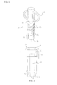
- FIGS. 1 and 2 show a medical connector according to a preferred embodiment of the invention.
- the connector is integral and obtained here by injection molding a medically inert thermoplastic material. It may, purely for illustrative purposes, be made of polycarbonate or derivatives thereof, polyolefin (such as polyethylene, polypropylene, a homopolymer or a copolymer of polypropylene) or polystyrene, or polyolefin comprising a thermoplastic elastomer (TPE) such as SEB (block copolymer Styrene, Ethylene, Butylene), SEBS (block copolymer Styrene, Ethylene, Butylene, Styrene) ...
- TPE thermoplastic elastomer
- This connector 1 comprises a pipe 2 defining internally a liquid flow channel between an upstream end 3 and a downstream end 4 of this connector, these ends 3, 4 being considered in the direction of liquid flow from a flexible bag to which this connector 1 would be integral.
- the upstream end 3 comprises an inlet 5 of the liquids. This channel is first delimited by a first tubular or substantially tubular portion 6 of diameter d 1 .
- This first portion 6 is separated by an internal sealing membrane 7.
- This sealing membrane 7 which is breakable, closes the passage for the fluid to pass into the connector.
- the tubing 2 also has on its outer surface a flange 8, or ring, which provides, on the one hand, the grip or using a robot of this connector 1 and, on the other hand, forms a stop whose position relative to the upstream end 3 of this connector has determined during a shaping step of this connector on a deformation tool, the dimensions of its so-called deformed portion 9.
- This so-called deformed part 9, or pleated thus defines a channel portion 10 distinct from that delimited by the first tubular portion 6 and placed between the sealing membrane 7 and the upstream end 3 of the connector.
- This portion of channel 10 has a narrowed shape, that is to say that it has a diameter d 2 which decreases going towards the upstream end 3 of the connector.
- This diameter d 2 however satisfies in every respect the following relation d 1 -d 2 ⁇ 0.1 d 1 whatever the temperature Tc of this connector with Tc between [T RT , T input [where T RT is the ambient temperature and The inlet is the melting temperature of said thermoplastic material.
- a breakable element 11 is also placed at the downstream end 4 of the connector being connected by a thin bridging 12 to the upper end of the pipe 2.
- This breakable element 11 is a quarter-turn plug.
- This quarter turn plug 11 can be detached from the tubing 2 by a simple manual rotation of a quarter turn.
- the tubing 2 also has on its outer surface fins 13 for gripping to easily separate the quarter turn plug 11 of the body of the tubing 2.
- This quarter-turn plug 11 has in its upper part a plug 14 hermetically closing a channel 15 of this plug which is in fluid communication with the channel defined by the first tubular portion 6 of the tubing 2.
- the Figure 3 shows a connector according to a second embodiment of the invention.
- the elements of the Figure 3 bearing the same references as the elements of the Figures 1 and 2 represent the same objects, which will not be described again below.
- This connector 1 differs from that described in Figures 1 and 2 , in particular in that it comprises a pipe 2 having on its outer surface a thread 16 intended to cooperate, in known manner, with a cylindrical ferrule coupling a male luer connector of a transfer set for example.
- this connector does not have gripping fins 13.
- a connector comprising a straight pipe 2 of constant diameter d 1 equal to 7.10 mm and of length 11.7 mm, has seen its upstream end. 3 folded, or deformed, on a deformation tool whose crimping angle is 45 °.
- the distance separating the lower end of the flange 8 from the upstream end 3 of this connector before deformation is 10.45 mm.
- the crimping angle is preferably between 15 ° and 75 °, and more preferably between 30 ° and 45 ° with respect to the longitudinal axis of the tubing.
- the Figure 4 is a sectional view of a medical connector according to a third embodiment of the invention.
- the elements of the Figure 4 bearing the same references as the elements of the Figures 1 and 2 represent the same objects, which will not be described again below.
- This connector has an internal channel for the passage of a fluid.
- a first portion of this channel is delimited by a first tubular portion 6 of the connector having a diameter d 1 .
- This first portion 6 has at its end defining the downstream end 4 of the connector a sealing bead 17. It is furthermore separated by a sealed and breakable shutter 18 of a second tubular portion 19 defining a channel of constant internal diameter d 2 restricted with respect to the diameter d 1 of the channel delimited by the first portion 6.
- This second portion 19 is extended towards the upstream end 3 of the connector by a third portion 9 said deformed.
- This portion 9 said deformed is distinct from the first portion 6 being placed between the sealed shutter 18 and the upstream end 3 of the connector.
- This so-called deformed portion 9 delimits an internal channel of decreasing diameter from the second portion 18 of the connector to the upstream end 5 thereof.
- This so-called deformed portion 9 comprises a set of n successive deformed portions, of which at least one part delimiting an internal channel portion of diameter d 3 is such that d 1 -d 3 ⁇ 0.10 d 1 whatever the temperature Tc of this connector with Tc lying between [T RT , T input [where T RT is the ambient temperature and T input is the melting temperature of said thermoplastic material.
- the inlet port 5 here has an orifice diameter such that d 1 -d orifice ⁇ 0.2 d 1 .
Landscapes
- Health & Medical Sciences (AREA)
- Heart & Thoracic Surgery (AREA)
- Life Sciences & Earth Sciences (AREA)
- Animal Behavior & Ethology (AREA)
- General Health & Medical Sciences (AREA)
- Public Health (AREA)
- Veterinary Medicine (AREA)
- Pulmonology (AREA)
- Pharmacology & Pharmacy (AREA)
- Engineering & Computer Science (AREA)
- Anesthesiology (AREA)
- Biomedical Technology (AREA)
- Hematology (AREA)
- Infusion, Injection, And Reservoir Apparatuses (AREA)
- Quick-Acting Or Multi-Walled Pipe Joints (AREA)
- Separation Using Semi-Permeable Membranes (AREA)
Applications Claiming Priority (1)
| Application Number | Priority Date | Filing Date | Title |
|---|---|---|---|
| FR1053956A FR2960155B1 (fr) | 2010-05-21 | 2010-05-21 | Connecteur pour un circuit de liquide |
Publications (3)
| Publication Number | Publication Date |
|---|---|
| EP2388042A2 true EP2388042A2 (de) | 2011-11-23 |
| EP2388042A3 EP2388042A3 (de) | 2013-08-14 |
| EP2388042B1 EP2388042B1 (de) | 2020-04-29 |
Family
ID=42667966
Family Applications (1)
| Application Number | Title | Priority Date | Filing Date |
|---|---|---|---|
| EP11166964.4A Active EP2388042B1 (de) | 2010-05-21 | 2011-05-20 | Anschluss für einen Flüssigkeitskreislauf |
Country Status (2)
| Country | Link |
|---|---|
| EP (1) | EP2388042B1 (de) |
| FR (1) | FR2960155B1 (de) |
Cited By (4)
| Publication number | Priority date | Publication date | Assignee | Title |
|---|---|---|---|---|
| EP2636400A1 (de) * | 2012-03-09 | 2013-09-11 | Fenwal, Inc. | Steriler öffnungsfähiger Zugangsport und Behälter damit |
| US20190046407A1 (en) * | 2017-08-09 | 2019-02-14 | Fresenius Medical Care Holdings, Inc. | Spike port for medical solution bag assembly and related methods |
| EP4403203A4 (de) * | 2021-09-13 | 2025-06-25 | Ishikita, Naoyuki | Ansaugführungsrohr und ansaugsaugsystem |
| US12539381B2 (en) | 2021-09-15 | 2026-02-03 | Naoyuki Ishikita | Suction-target guide pipe and suction-target suction system |
Family Cites Families (4)
| Publication number | Priority date | Publication date | Assignee | Title |
|---|---|---|---|---|
| US4349024A (en) * | 1981-04-01 | 1982-09-14 | Ralston Jr Philip G | Multiple adapter device for interconnecting tubing of different sizes |
| DE102004050603B3 (de) * | 2004-10-15 | 2006-06-01 | Plümat Plate & Lübeck GmbH & Co. | Kunststoffbeutel mit einem oder mehreren Ports sowie Kunststoffelement für einen Port |
| KR101312824B1 (ko) * | 2007-06-08 | 2013-09-27 | 가부시끼가이샤 제이엠에스 | 숫형 커넥터 |
| GB0816704D0 (en) * | 2008-09-12 | 2008-10-22 | Link Ltd B | Medical device |
-
2010
- 2010-05-21 FR FR1053956A patent/FR2960155B1/fr not_active Expired - Fee Related
-
2011
- 2011-05-20 EP EP11166964.4A patent/EP2388042B1/de active Active
Non-Patent Citations (1)
| Title |
|---|
| None |
Cited By (7)
| Publication number | Priority date | Publication date | Assignee | Title |
|---|---|---|---|---|
| EP2636400A1 (de) * | 2012-03-09 | 2013-09-11 | Fenwal, Inc. | Steriler öffnungsfähiger Zugangsport und Behälter damit |
| US9005181B2 (en) | 2012-03-09 | 2015-04-14 | Fenwal, Inc. | Sterile openable access port and containers including the same |
| US20190046407A1 (en) * | 2017-08-09 | 2019-02-14 | Fresenius Medical Care Holdings, Inc. | Spike port for medical solution bag assembly and related methods |
| WO2019032344A1 (en) * | 2017-08-09 | 2019-02-14 | Fresenius Medical Care Holdings, Inc. | TROCARDABLE TOOL FOR MEDICAL SOLUTION PACKAGE ASSEMBLY AND ASSOCIATED METHODS |
| CN110997037A (zh) * | 2017-08-09 | 2020-04-10 | 费森尤斯医疗保健控股公司 | 用于医疗溶液袋组件的尖峰端口和相关方法 |
| EP4403203A4 (de) * | 2021-09-13 | 2025-06-25 | Ishikita, Naoyuki | Ansaugführungsrohr und ansaugsaugsystem |
| US12539381B2 (en) | 2021-09-15 | 2026-02-03 | Naoyuki Ishikita | Suction-target guide pipe and suction-target suction system |
Also Published As
| Publication number | Publication date |
|---|---|
| FR2960155A1 (fr) | 2011-11-25 |
| FR2960155B1 (fr) | 2014-01-17 |
| EP2388042A3 (de) | 2013-08-14 |
| EP2388042B1 (de) | 2020-04-29 |
Similar Documents
| Publication | Publication Date | Title |
|---|---|---|
| EP2825246A1 (de) | Sichere anordnung zur flüssigkeitsübertragung für medizinische zwecke | |
| EP3014162B1 (de) | Neutraler fluidstecker mit klammer und schutz | |
| EP2999450B1 (de) | Stopfen für verbinder für einen infusionsbeutel | |
| FR3046206A1 (fr) | Procede de fabrication d'un recipient etanche | |
| EP2388042B1 (de) | Anschluss für einen Flüssigkeitskreislauf | |
| CA2793097A1 (fr) | Systeme securise de transfert de liquide a usage medical | |
| EP4031231B1 (de) | Einstückiger verbinder für einen flexiblen infusionsbeutel | |
| EP2999449A1 (de) | Basis für einen verbinder für einen infusionsbeutel | |
| EP3302351B1 (de) | Trinkhalm zum einhalten einer vorbestimmten dosis einer flüssigkeitsbasierten substanz sowie injektionsvorrichtung und verfahren damit | |
| EP2253298B1 (de) | Verbinder für einen flexiblen Behälter zur Aufnahme von medizinischer Flüssigkeit | |
| EP3436133B1 (de) | Öffnung, abgabesystem mit solch einer öffnung und herstellungsverfahren | |
| EP1144901B1 (de) | Vorrichtung zum anschliessen einer zweigleitung an eine fluidführende leitung | |
| EP1405710A1 (de) | Weithalsvorformling mit Schutz gegen mechanische Schäden des Innenabdichtungsbereichs | |
| EP2818308A1 (de) | Verfahren zur Herstellung eines Anschlusses | |
| CA2470224A1 (fr) | Embout perfuseur pour poche souple a usage medical | |
| WO2014207368A1 (fr) | Connecteur fluidique avec collier et protection | |
| FR3134316A1 (fr) | Robinet médical | |
| EP2146923A2 (de) | Verschlussdeckel für einen behälter zur aufbewahrung von kohlensäurehaltigen flüssigkeiten und behälter mit derartigem verschluss | |
| FR3110897A1 (fr) | Bouchon connecteur pour fût | |
| FR2978426A1 (fr) | Procede de remplissage d'un recipient souple | |
| FR2726809A1 (fr) | Dispositif de bouchon verseur |
Legal Events
| Date | Code | Title | Description |
|---|---|---|---|
| AK | Designated contracting states |
Kind code of ref document: A2 Designated state(s): AL AT BE BG CH CY CZ DE DK EE ES FI FR GB GR HR HU IE IS IT LI LT LU LV MC MK MT NL NO PL PT RO RS SE SI SK SM TR |
|
| AX | Request for extension of the european patent |
Extension state: BA ME |
|
| PUAI | Public reference made under article 153(3) epc to a published international application that has entered the european phase |
Free format text: ORIGINAL CODE: 0009012 |
|
| PUAL | Search report despatched |
Free format text: ORIGINAL CODE: 0009013 |
|
| AK | Designated contracting states |
Kind code of ref document: A3 Designated state(s): AL AT BE BG CH CY CZ DE DK EE ES FI FR GB GR HR HU IE IS IT LI LT LU LV MC MK MT NL NO PL PT RO RS SE SI SK SM TR |
|
| AX | Request for extension of the european patent |
Extension state: BA ME |
|
| RIC1 | Information provided on ipc code assigned before grant |
Ipc: A61J 1/10 20060101ALI20130709BHEP Ipc: A61J 1/14 20060101ALN20130709BHEP Ipc: A61M 5/00 20060101ALN20130709BHEP Ipc: A61M 39/10 20060101AFI20130709BHEP Ipc: A61J 1/00 20060101ALN20130709BHEP |
|
| 17P | Request for examination filed |
Effective date: 20140204 |
|
| RBV | Designated contracting states (corrected) |
Designated state(s): AL AT BE BG CH CY CZ DE DK EE ES FI FR GB GR HR HU IE IS IT LI LT LU LV MC MK MT NL NO PL PT RO RS SE SI SK SM TR |
|
| STAA | Information on the status of an ep patent application or granted ep patent |
Free format text: STATUS: EXAMINATION IS IN PROGRESS |
|
| 17Q | First examination report despatched |
Effective date: 20170315 |
|
| GRAP | Despatch of communication of intention to grant a patent |
Free format text: ORIGINAL CODE: EPIDOSNIGR1 |
|
| STAA | Information on the status of an ep patent application or granted ep patent |
Free format text: STATUS: GRANT OF PATENT IS INTENDED |
|
| RIC1 | Information provided on ipc code assigned before grant |
Ipc: A61J 1/00 20060101ALN20191022BHEP Ipc: A61J 1/10 20060101ALI20191022BHEP Ipc: A61J 1/14 20060101ALN20191022BHEP Ipc: A61M 39/10 20060101AFI20191022BHEP Ipc: A61M 5/00 20060101ALN20191022BHEP |
|
| INTG | Intention to grant announced |
Effective date: 20191120 |
|
| GRAS | Grant fee paid |
Free format text: ORIGINAL CODE: EPIDOSNIGR3 |
|
| GRAA | (expected) grant |
Free format text: ORIGINAL CODE: 0009210 |
|
| STAA | Information on the status of an ep patent application or granted ep patent |
Free format text: STATUS: THE PATENT HAS BEEN GRANTED |
|
| AK | Designated contracting states |
Kind code of ref document: B1 Designated state(s): AL AT BE BG CH CY CZ DE DK EE ES FI FR GB GR HR HU IE IS IT LI LT LU LV MC MK MT NL NO PL PT RO RS SE SI SK SM TR |
|
| REG | Reference to a national code |
Ref country code: GB Ref legal event code: FG4D Free format text: NOT ENGLISH |
|
| REG | Reference to a national code |
Ref country code: CH Ref legal event code: EP |
|
| REG | Reference to a national code |
Ref country code: DE Ref legal event code: R096 Ref document number: 602011066486 Country of ref document: DE |
|
| REG | Reference to a national code |
Ref country code: AT Ref legal event code: REF Ref document number: 1262383 Country of ref document: AT Kind code of ref document: T Effective date: 20200515 |
|
| REG | Reference to a national code |
Ref country code: IE Ref legal event code: FG4D Free format text: LANGUAGE OF EP DOCUMENT: FRENCH |
|
| REG | Reference to a national code |
Ref country code: NL Ref legal event code: MP Effective date: 20200429 |
|
| REG | Reference to a national code |
Ref country code: LT Ref legal event code: MG4D |
|
| PG25 | Lapsed in a contracting state [announced via postgrant information from national office to epo] |
Ref country code: GR Free format text: LAPSE BECAUSE OF FAILURE TO SUBMIT A TRANSLATION OF THE DESCRIPTION OR TO PAY THE FEE WITHIN THE PRESCRIBED TIME-LIMIT Effective date: 20200730 Ref country code: PT Free format text: LAPSE BECAUSE OF FAILURE TO SUBMIT A TRANSLATION OF THE DESCRIPTION OR TO PAY THE FEE WITHIN THE PRESCRIBED TIME-LIMIT Effective date: 20200831 Ref country code: IS Free format text: LAPSE BECAUSE OF FAILURE TO SUBMIT A TRANSLATION OF THE DESCRIPTION OR TO PAY THE FEE WITHIN THE PRESCRIBED TIME-LIMIT Effective date: 20200829 Ref country code: NO Free format text: LAPSE BECAUSE OF FAILURE TO SUBMIT A TRANSLATION OF THE DESCRIPTION OR TO PAY THE FEE WITHIN THE PRESCRIBED TIME-LIMIT Effective date: 20200729 Ref country code: SE Free format text: LAPSE BECAUSE OF FAILURE TO SUBMIT A TRANSLATION OF THE DESCRIPTION OR TO PAY THE FEE WITHIN THE PRESCRIBED TIME-LIMIT Effective date: 20200429 Ref country code: FI Free format text: LAPSE BECAUSE OF FAILURE TO SUBMIT A TRANSLATION OF THE DESCRIPTION OR TO PAY THE FEE WITHIN THE PRESCRIBED TIME-LIMIT Effective date: 20200429 Ref country code: LT Free format text: LAPSE BECAUSE OF FAILURE TO SUBMIT A TRANSLATION OF THE DESCRIPTION OR TO PAY THE FEE WITHIN THE PRESCRIBED TIME-LIMIT Effective date: 20200429 |
|
| REG | Reference to a national code |
Ref country code: AT Ref legal event code: MK05 Ref document number: 1262383 Country of ref document: AT Kind code of ref document: T Effective date: 20200429 |
|
| PG25 | Lapsed in a contracting state [announced via postgrant information from national office to epo] |
Ref country code: RS Free format text: LAPSE BECAUSE OF FAILURE TO SUBMIT A TRANSLATION OF THE DESCRIPTION OR TO PAY THE FEE WITHIN THE PRESCRIBED TIME-LIMIT Effective date: 20200429 Ref country code: HR Free format text: LAPSE BECAUSE OF FAILURE TO SUBMIT A TRANSLATION OF THE DESCRIPTION OR TO PAY THE FEE WITHIN THE PRESCRIBED TIME-LIMIT Effective date: 20200429 Ref country code: LV Free format text: LAPSE BECAUSE OF FAILURE TO SUBMIT A TRANSLATION OF THE DESCRIPTION OR TO PAY THE FEE WITHIN THE PRESCRIBED TIME-LIMIT Effective date: 20200429 Ref country code: BG Free format text: LAPSE BECAUSE OF FAILURE TO SUBMIT A TRANSLATION OF THE DESCRIPTION OR TO PAY THE FEE WITHIN THE PRESCRIBED TIME-LIMIT Effective date: 20200729 |
|
| REG | Reference to a national code |
Ref country code: DE Ref legal event code: R119 Ref document number: 602011066486 Country of ref document: DE |
|
| PG25 | Lapsed in a contracting state [announced via postgrant information from national office to epo] |
Ref country code: NL Free format text: LAPSE BECAUSE OF FAILURE TO SUBMIT A TRANSLATION OF THE DESCRIPTION OR TO PAY THE FEE WITHIN THE PRESCRIBED TIME-LIMIT Effective date: 20200429 Ref country code: AL Free format text: LAPSE BECAUSE OF FAILURE TO SUBMIT A TRANSLATION OF THE DESCRIPTION OR TO PAY THE FEE WITHIN THE PRESCRIBED TIME-LIMIT Effective date: 20200429 |
|
| PG25 | Lapsed in a contracting state [announced via postgrant information from national office to epo] |
Ref country code: RO Free format text: LAPSE BECAUSE OF FAILURE TO SUBMIT A TRANSLATION OF THE DESCRIPTION OR TO PAY THE FEE WITHIN THE PRESCRIBED TIME-LIMIT Effective date: 20200429 Ref country code: IT Free format text: LAPSE BECAUSE OF FAILURE TO SUBMIT A TRANSLATION OF THE DESCRIPTION OR TO PAY THE FEE WITHIN THE PRESCRIBED TIME-LIMIT Effective date: 20200429 Ref country code: SM Free format text: LAPSE BECAUSE OF FAILURE TO SUBMIT A TRANSLATION OF THE DESCRIPTION OR TO PAY THE FEE WITHIN THE PRESCRIBED TIME-LIMIT Effective date: 20200429 Ref country code: EE Free format text: LAPSE BECAUSE OF FAILURE TO SUBMIT A TRANSLATION OF THE DESCRIPTION OR TO PAY THE FEE WITHIN THE PRESCRIBED TIME-LIMIT Effective date: 20200429 Ref country code: DK Free format text: LAPSE BECAUSE OF FAILURE TO SUBMIT A TRANSLATION OF THE DESCRIPTION OR TO PAY THE FEE WITHIN THE PRESCRIBED TIME-LIMIT Effective date: 20200429 Ref country code: LI Free format text: LAPSE BECAUSE OF NON-PAYMENT OF DUE FEES Effective date: 20200531 Ref country code: MC Free format text: LAPSE BECAUSE OF FAILURE TO SUBMIT A TRANSLATION OF THE DESCRIPTION OR TO PAY THE FEE WITHIN THE PRESCRIBED TIME-LIMIT Effective date: 20200429 Ref country code: AT Free format text: LAPSE BECAUSE OF FAILURE TO SUBMIT A TRANSLATION OF THE DESCRIPTION OR TO PAY THE FEE WITHIN THE PRESCRIBED TIME-LIMIT Effective date: 20200429 Ref country code: CZ Free format text: LAPSE BECAUSE OF FAILURE TO SUBMIT A TRANSLATION OF THE DESCRIPTION OR TO PAY THE FEE WITHIN THE PRESCRIBED TIME-LIMIT Effective date: 20200429 Ref country code: CH Free format text: LAPSE BECAUSE OF NON-PAYMENT OF DUE FEES Effective date: 20200531 Ref country code: ES Free format text: LAPSE BECAUSE OF FAILURE TO SUBMIT A TRANSLATION OF THE DESCRIPTION OR TO PAY THE FEE WITHIN THE PRESCRIBED TIME-LIMIT Effective date: 20200429 |
|
| PG25 | Lapsed in a contracting state [announced via postgrant information from national office to epo] |
Ref country code: SK Free format text: LAPSE BECAUSE OF FAILURE TO SUBMIT A TRANSLATION OF THE DESCRIPTION OR TO PAY THE FEE WITHIN THE PRESCRIBED TIME-LIMIT Effective date: 20200429 Ref country code: PL Free format text: LAPSE BECAUSE OF FAILURE TO SUBMIT A TRANSLATION OF THE DESCRIPTION OR TO PAY THE FEE WITHIN THE PRESCRIBED TIME-LIMIT Effective date: 20200429 |
|
| PLBE | No opposition filed within time limit |
Free format text: ORIGINAL CODE: 0009261 |
|
| STAA | Information on the status of an ep patent application or granted ep patent |
Free format text: STATUS: NO OPPOSITION FILED WITHIN TIME LIMIT |
|
| REG | Reference to a national code |
Ref country code: BE Ref legal event code: MM Effective date: 20200531 |
|
| GBPC | Gb: european patent ceased through non-payment of renewal fee |
Effective date: 20200729 |
|
| PG25 | Lapsed in a contracting state [announced via postgrant information from national office to epo] |
Ref country code: LU Free format text: LAPSE BECAUSE OF NON-PAYMENT OF DUE FEES Effective date: 20200520 |
|
| 26N | No opposition filed |
Effective date: 20210201 |
|
| PG25 | Lapsed in a contracting state [announced via postgrant information from national office to epo] |
Ref country code: IE Free format text: LAPSE BECAUSE OF NON-PAYMENT OF DUE FEES Effective date: 20200520 Ref country code: FR Free format text: LAPSE BECAUSE OF NON-PAYMENT OF DUE FEES Effective date: 20200629 Ref country code: GB Free format text: LAPSE BECAUSE OF NON-PAYMENT OF DUE FEES Effective date: 20200729 |
|
| PG25 | Lapsed in a contracting state [announced via postgrant information from national office to epo] |
Ref country code: SI Free format text: LAPSE BECAUSE OF FAILURE TO SUBMIT A TRANSLATION OF THE DESCRIPTION OR TO PAY THE FEE WITHIN THE PRESCRIBED TIME-LIMIT Effective date: 20200429 Ref country code: BE Free format text: LAPSE BECAUSE OF NON-PAYMENT OF DUE FEES Effective date: 20200531 Ref country code: DE Free format text: LAPSE BECAUSE OF NON-PAYMENT OF DUE FEES Effective date: 20201201 |
|
| PG25 | Lapsed in a contracting state [announced via postgrant information from national office to epo] |
Ref country code: TR Free format text: LAPSE BECAUSE OF FAILURE TO SUBMIT A TRANSLATION OF THE DESCRIPTION OR TO PAY THE FEE WITHIN THE PRESCRIBED TIME-LIMIT Effective date: 20200429 Ref country code: MT Free format text: LAPSE BECAUSE OF FAILURE TO SUBMIT A TRANSLATION OF THE DESCRIPTION OR TO PAY THE FEE WITHIN THE PRESCRIBED TIME-LIMIT Effective date: 20200429 Ref country code: CY Free format text: LAPSE BECAUSE OF FAILURE TO SUBMIT A TRANSLATION OF THE DESCRIPTION OR TO PAY THE FEE WITHIN THE PRESCRIBED TIME-LIMIT Effective date: 20200429 |
|
| PG25 | Lapsed in a contracting state [announced via postgrant information from national office to epo] |
Ref country code: MK Free format text: LAPSE BECAUSE OF FAILURE TO SUBMIT A TRANSLATION OF THE DESCRIPTION OR TO PAY THE FEE WITHIN THE PRESCRIBED TIME-LIMIT Effective date: 20200429 |