EP2388108A2 - Établi pour supporter des pièces de travail - Google Patents
Établi pour supporter des pièces de travail Download PDFInfo
- Publication number
- EP2388108A2 EP2388108A2 EP11380041A EP11380041A EP2388108A2 EP 2388108 A2 EP2388108 A2 EP 2388108A2 EP 11380041 A EP11380041 A EP 11380041A EP 11380041 A EP11380041 A EP 11380041A EP 2388108 A2 EP2388108 A2 EP 2388108A2
- Authority
- EP
- European Patent Office
- Prior art keywords
- bars
- guide rails
- supporting
- framework
- elements
- Prior art date
- Legal status (The legal status is an assumption and is not a legal conclusion. Google has not performed a legal analysis and makes no representation as to the accuracy of the status listed.)
- Withdrawn
Links
- 239000004411 aluminium Substances 0.000 claims description 11
- 229910052782 aluminium Inorganic materials 0.000 claims description 11
- XAGFODPZIPBFFR-UHFFFAOYSA-N aluminium Chemical compound [Al] XAGFODPZIPBFFR-UHFFFAOYSA-N 0.000 claims description 11
- 229910052751 metal Inorganic materials 0.000 description 3
- 239000002184 metal Substances 0.000 description 3
- XEEYBQQBJWHFJM-UHFFFAOYSA-N Iron Chemical compound [Fe] XEEYBQQBJWHFJM-UHFFFAOYSA-N 0.000 description 2
- 208000029154 Narrow face Diseases 0.000 description 2
- 238000010276 construction Methods 0.000 description 2
- -1 among others Substances 0.000 description 1
- 238000005520 cutting process Methods 0.000 description 1
- 238000005553 drilling Methods 0.000 description 1
- 229910052742 iron Inorganic materials 0.000 description 1
- 239000000463 material Substances 0.000 description 1
- 230000004048 modification Effects 0.000 description 1
- 238000012986 modification Methods 0.000 description 1
- 239000004033 plastic Substances 0.000 description 1
- 238000005498 polishing Methods 0.000 description 1
- 238000003466 welding Methods 0.000 description 1
- 239000002023 wood Substances 0.000 description 1
Images


Classifications
-
- B—PERFORMING OPERATIONS; TRANSPORTING
- B25—HAND TOOLS; PORTABLE POWER-DRIVEN TOOLS; MANIPULATORS
- B25H—WORKSHOP EQUIPMENT, e.g. FOR MARKING-OUT WORK; STORAGE MEANS FOR WORKSHOPS
- B25H1/00—Work benches; Portable stands or supports for positioning portable tools or work to be operated on thereby
- B25H1/10—Work benches; Portable stands or supports for positioning portable tools or work to be operated on thereby with provision for adjusting holders for tool or work
-
- B—PERFORMING OPERATIONS; TRANSPORTING
- B25—HAND TOOLS; PORTABLE POWER-DRIVEN TOOLS; MANIPULATORS
- B25H—WORKSHOP EQUIPMENT, e.g. FOR MARKING-OUT WORK; STORAGE MEANS FOR WORKSHOPS
- B25H1/00—Work benches; Portable stands or supports for positioning portable tools or work to be operated on thereby
- B25H1/14—Work benches; Portable stands or supports for positioning portable tools or work to be operated on thereby with provision for adjusting the bench top
- B25H1/18—Work benches; Portable stands or supports for positioning portable tools or work to be operated on thereby with provision for adjusting the bench top in inclination
Definitions
- the present invention relates to a workbench useful for supporting one or more workpieces on which one or more operations are to be performed, such as for example welding, drilling, cutting, filing, polishing, etc.
- the workbench of the present invention is mainly, although not exclusively, applicable in the metal fittings and ironwork field.
- a table provided with a horizontal upper face which is perpendicularly extended in side skirts is currently used as a workbench in the metal fittings and ironwork field.
- a drawback of this workbench in the form of a table is that the upper surface does not allow the workpieces to project from the lower part thereof unless they are supported outside the extension of the upper surface by means of supporting elements in the form of side extensions and the like.
- Another drawback is that the upper surface prevents accessing the lower areas of the workpieces which are secured thereon, and although it is possible to access the lower areas of the workpieces which are secured outside the work surface by means of extensions, this is very uncomfortable because it forces adopting squatting positions.
- the regularly distributed orifices on the upper surface and side skirts of the table determine rigid positions for the accessory elements and do not allow a continuous sliding for selecting the ideal position thereof.
- Patent US-A-5131253 describes a workbench provided to support vehicle chassis and bodywork parts in order to repair them.
- the workbench comprises a rectangular frame supporting a plurality of transverse bars which can slide along guide rails existing in the stringers of the frame and which can be fixed in desired positions by locking means.
- Accessory elements comprising positioning elements and supporting elements can slide along guide rails formed in the transverse bars and can be fixed in desired positions by locking means.
- a drawback of this workbench is that not all the bars forming it include guide rails, and those which have them only include one guide rail in one of their faces. This makes the workbench non-versatile when the workpieces to be secured are single or small-series parts that are very different from one another, as occurs in the metal fitting and ironwork field.
- the present invention contributes to solving the previous and other drawbacks by providing a workbench for supporting workpieces which comprises a framework formed by a plurality of bars connected to one another, where said bars have longitudinal guide rails along which accessory elements can slide, which accessory elements are selected from supporting elements, positioning elements and gripping elements useful for supporting, positioning and/or gripping one or more workpieces.
- Locking means are provided for locking said accessory elements in any position along said guide rails.
- Each of the bars forming said framework has a plurality of longitudinal faces and at least one of said guide rails is arranged on at least three of said longitudinal faces.
- the framework has the form of a quadrangular frame, generally rectangular or square, formed by four of the bars connected at their ends, although alternatively the framework could be formed by a different number of bars and could have any other form, including an open form, such as a U shape for example.
- the bars forming the framework have a quadrangular cross-section, although other sections such as such as triangular, hexagonal, octagonal, etc. are not ruled out.
- the framework it is advantageous for the framework to have the form of a square or rectangular frame formed by four bars with a square or rectangular cross-section, such that the four bars forming the framework have respective mutually parallel and preferably flush upper faces, respective mutually parallel and preferably flush lower faces, respective mutually perpendicular inner side faces and respective mutually perpendicular outer side faces.
- the framework has a square or rectangular form formed by four bars with a square or rectangular cross-section, and each of the four bars has at least one guide rail on each of its upper, lower, inner side and outer side faces.
- one or more of the bars forming the framework can have two parallel longitudinal guide rails on one or more of the longitudinal faces thereof.
- the framework is supported such that it can pivot with respect to a horizontal rotation shaft connected to the framework and supported in a supporting structure, and can be fixed in any angular position with respect to said supporting structure by locking means.
- the supporting structure can be formed by a mobile rack in which the mentioned horizontal rotation shaft with respect to which the framework rotates is supported, and a base supporting said mobile rack such that the latter can rotate with respect to a vertical shaft.
- the aforementioned supporting elements which can be fixed to the framework using the guide rails and locking means, include auxiliary bars and rotating plates.
- the auxiliary bars have in turn guide rails along which others supporting elements and/or positioning elements and/or gripping elements can slide and can be fixed by means of corresponding locking means.
- the rotating plates have a fixed part which can be fixed in a desired position in the framework or in an auxiliary bar, and a mobile part which can rotate with respect to the fixed part and which can be fixed in a desired angular position by means of locking means.
- the mobile part of the rotating plate can in turn support other supporting elements and/or positioning elements and/or gripping elements.
- a linear graduated ruler associated with one or more of the guide rails and an angular graduated ruler can be arranged in the rotating plates.
- linear and angular graduated rulers are usable as a reference for positioning other accessory elements.
- the workbench of the present invention allows supporting one or more workpieces virtually in any position of the Cartesian space (x, y, z axes), above, below, inside and outside the framework and in its vicinity. Furthermore, by virtue of the capacity of the framework for rotating on two shafts, it is possible to place the framework in an enormous variety of positions to provide a comfortable and direct access to virtually any area of the secured workpieces without needing to adopt squatting or uncomfortable positions. Furthermore, the position of the framework can easily be changed to provide an easy access to different areas of one and the same workpiece without needing to loosen it and secure it again.
- the bars forming the framework and the auxiliary bars are obtained from extruded aluminium profiles incorporating the guide rails in the form of longitudinal passages with an inlet slot narrower than a bottom channel, and slide elements and conventional locking means adapted to profiles of this type are used to fix the bars and accessory elements to one another.
- the supporting structure is preferably also formed by bars obtained from extruded aluminium profiles of the same type, although alternatively the supporting structure can comprise a conventional table or the framework can be installed on any other preexisting supporting structure.
- reference number 50 designates a workbench according to an embodiment of the present invention, which serves for supporting workpieces.
- the workbench 50 comprises a framework 1 with a rectangular shape formed by four bars 2 connected to one another at their ends.
- the framework 1 is supported such that it can pivot with respect to a horizontal rotation shaft A connected to the framework 1 and supported in a supporting structure 10, and can be fixed in any angular position with respect to said supporting structure 10 by locking means.
- the mentioned bars 2 have a rectangular cross-section and have four faces perpendicular to one another; two opposite wide faces and two opposite narrow faces. Along each of the two wide faces there are two parallel longitudinal guide rails 3 and along each of the two narrow faces there is one longitudinal guide rail 3.
- the bars 2 can have a square cross-section with a single guide rail 3 on each face, or they can even have other cross-sections with a different number of faces, although it is convenient for there to be at least one guide rail on at least three of said faces.
- the four bars 2 have respective mutually parallel and flush upper faces 2a, respective mutually parallel and flush lower faces 2b, respective mutually perpendicular inner side faces 2c and respective mutually perpendicular outer side faces 2d, and at least one guide rail 3 is arranged along each of them.
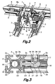
- Fig. 3 illustrates a known system for fixing the bars 2 to one another or for fixing other auxiliary bars to the bars 2 using the guide rails 3.
- the bars 2 of Fig. 3 are obtained, for example, from extruded aluminium profiles and have a square cross-section with a guide rail 3 on each of their faces 2a, 2b, 2c, 2d.
- Each guide rail 3 has the form of a longitudinal passage with an inlet slot 3a narrower than a bottom channel 3b.
- the bar 2 further has a hollow core 16 and a transverse hole 17 into which a sleeve 18 is fixedly inserted, which sleeve in turn has a transverse hole 19 aligned with the hollow core 16 of the bar 2.
- the mentioned sleeve 18 further has a threaded axial hole 20 in which there is coupled a conical tip screw 25 provided with a gripping head 26 configured to be gripped by means of a tool, such as a key with a hexagonal stem (not shown), to loosen or tighten the screw 25.
- a tool such as a key with a hexagonal stem (not shown)
- a fixing rod 21 is slidably inserted into the hollow core 16, which fixing rod has a head 22 configured to slide along the bottom channel 3b of one of the guide rails 3 but which cannot pass through the inlet slot 3a thereof and a narrower neck configured to pass through the inlet slot 3a.
- the fixing rod 21 further has a cavity 24 with inclined walls located such that the conical tip of the mentioned screw 25, when it is tightened, presses the inclined wall of the cavity 24 and drags the fixing rod 21 until pressing its head 22 against the inner part of the guide rail.
- any type of bars and accessory elements can be fixed to the bars 2 by using special screws (not shown), provided with a head and a neck similar to those of the fixing rod 21 described above, and corresponding nuts.
- the guide grooves 3 together with the fixing rod 21 and the screw 25, or with special screws and nuts, provide sliding means and locking means.
- the bars 2 of the framework 1 have notches 9 providing a side access to the bottom channel 3b of one or two of their guide rails 3, especially on the inner side faces 2c of the bars 2 which have the access to the guide rails 3 from the ends thereof hindered.
- the workbench 50 has associated therewith a set of accessory elements 4, 5, 6, 7 which by virtue of the sliding and locking means described in relation to Fig. 3 can slide along the longitudinal guide rails 3 and can be locked in any position along said guide rails 3.
- the mentioned accessory elements generally comprise supporting elements 5, 6, positioning elements 7 and gripping elements 4 useful for supporting, positioning and/or gripping one or more workpieces W.
- the positioning elements 7 and the gripping elements 4 can be directly supported in the bars 2 forming the framework 1 or can be supported in the mentioned additional supporting elements 5, 6 included in the mentioned accessory elements.
- the supporting elements include a pair of auxiliary bars 5 having longitudinal guide rails 3 along which other accessory elements 4, 5, 6, 7 can slide and be fixed.
- These auxiliary bars 5 are obtained from extruded aluminium profiles with a cross-section similar to that shown in Fig. 3 , such that they have guide rails 3 in the form of longitudinal passages with an inlet slot 3a narrower than a bottom channel 3b on all their faces.
- the auxiliary bars 5 are fixed in an abutted manner to the bars 2 of the framework 1 by means of fixing rods similar to that described above and the positioning elements 7 and the gripping elements 4 are fixed to the auxiliary bars by means of special screws, common screws and nuts (not shown) in selected positions for supporting three workpieces W in positions in which they must be mutually welded.
- the mentioned horizontal rotation shaft A is defined by a pair of mutually aligned rods 11 supported by first shaft supports 12 connected to the bars 2 located on opposite sides of the framework 1 and by second shaft supports 13 fixed to the supporting structure 10.
- the mentioned first shaft supports 12 are fixed to the corresponding bars 2 of the framework 1 such that they can slide along the guide rails 3 thereof and can be locked in any position along the guide rails 3 by the locking means.
- the supporting structure 10 comprises a mobile rack 10a and a base 10b supporting said mobile rack 10a.
- the mobile rack 10a has a U shape and is formed by a horizontal structure bar 15 and another two vertical structure bars 15 at the upper ends of which the second shaft supports 13 are fixed.
- the mentioned base 10b supports the mobile rack 10a such that the latter can rotate with respect to a vertical shaft B.
- the base 10b has crossed structure bars 15 for support on the floor and a right column 15a the upper end of which is connected by means of one of said fixing rods to a guide rail 3 of a horizontal structure bar 15 of the mobile rack 10a, such that when the fixing rod is loosened it can slide along the guide rail 3 of the horizontal structure bar 15 while at the same time it acts as said vertical shaft B allowing a free rotation of the mobile rack 10a with respect to the base 10b, and such that when the fixing rod is tightened it locks the mobile rack 10a with respect to the base 10b in any linear position along the guide rail 3 of the horizontal structure bar 15 of the mobile rack 10a and in any angular position.
- the vertical shaft B is connected to the mobile rack 10a and to the base 10b.
- the structure bars 15 which they form the supporting structure 10 can be obtained from extruded aluminium profiles including guide rails 3 in the form of longitudinal passages with an inlet slot 3a narrower than a bottom channel 3b, similar to the profile described in relation to Fig. 3 .
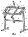
- Fig. 4 illustrates how the workbench can be extended beyond the framework 1 by using auxiliary supporting elements 5 in the form of aluminium profiles including guide rails 3 of the described type connected to the framework 1 by means of the sliding means and the locking means associated with this type of profiles.
- a pair of the supporting elements 5 are laterally fixed to the bars 2, another of them is fixed in an abutted manner in one of the bars 2 and extends towards a side, and yet another one is fixed in an abutted manner in one of the laterally fixed supporting elements 5 and extends towards an opposite side.
- the supporting structure 10 includes vertical and horizontal structure bars 15 connected to one another forming a single substantially H-shaped block.
- rotating plates which have the form of rotating plates 6 on which other accessory elements 4, 5, 6, 7 can be fixed.
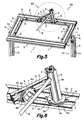
- the rotating plates have a fixed part 6a which can be fixed in a desired position in one of the bars 2 of the framework 1 or in an auxiliary bar 5 using special screws such as those described above coupled to the guide rails 3, and a mobile part 6b which can rotate with respect to the fixed part 6a and which can be fixed in a desired angular position by locking means, such as screws passed through curved elongated holes 6c.
- the mobile part 6b of the rotating plate 6 can in turn support other supporting elements and/or positioning elements and/or gripping elements.
- a first rotating plate 6 located on the right of the drawing is fixed to a bar 2 of the framework 1 and supports a first auxiliary bar 5 extending perpendicular to the bar 2 although rotated an angle with respect to same. From the first auxiliary bar 5 there extends a second auxiliary bar 5 supporting a second rotating plate 6, which in turn supports a positioning element 7 contributing in positioning a workpiece W, which will be additionally positioned and secured by other positioning elements 7 and gripping elements 4 (not shown).
- a linear graduated ruler 8a provided to be used as a reference for the linear positioning of the accessory elements 4, 5, 6, 7 supported therein
- the rotating plates 6 have indicated therein an angular graduated ruler 8b usable as a reference for positioning the accessory elements 4, 5, 6, 7 supported thereon.
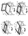
- FIG. 7 to 10 another embodiment of the workbench of the present invention is described, which includes a framework 1 made of bars 2 with guide rails 3 similar to the one described above, and it only differs from the embodiment described above in relation to Fig. 1 in the construction of the supporting structure 10, which here has the form of a conventional table 27.
- the table 27 can be made of any material, including, among others, wood, iron, aluminium, plastic and combinations thereof.
- the table 27 can be a preexisting table at a user's disposal.
- Parallel supporting bars 14 are fixed on the table 27, which parallel supporting bars are obtained from extruded aluminium profiles having guide rails 3 in the form of longitudinal passages with an inlet slot 3a narrower than a bottom channel 3b, similar to the profiles described above in relation to Fig. 3 .
- respective fixing rods 21 for example, similar to those described in relation to Fig. 3
- the heads 22 of which can slide along the guide rails 3 of the supporting bars 14 fixed to the table 27 and can be locked in any linear position along the guide rails 3 and in any angular position by the locking means described above.
- the framework 1 is arranged on top of the table 27 and parallel thereto.
- the framework 1 is arranged perpendicular to the table 27 adjacent to a rear edge thereof.
- the framework 1 is arranged extending in a projected manner outside the table 27 and parallel thereto.
- the framework is arranged on the table 27 forming an angle therewith. It will be understood that the arrangements shown in Figs. 7 to 10 are mere examples of the infinite configurations which can be adopted by the framework 1 with respect to the table 27.
- Fig. 11 shows an exploded view of the components forming the workbench according to the basic embodiment of Fig. 4
- Fig. 12 shows the same components grouped to adopt the mentioned compact configuration.
Landscapes
- Engineering & Computer Science (AREA)
- Mechanical Engineering (AREA)
- Workshop Equipment, Work Benches, Supports, Or Storage Means (AREA)
- Jigs For Machine Tools (AREA)
Applications Claiming Priority (1)
| Application Number | Priority Date | Filing Date | Title |
|---|---|---|---|
| ES201000522U ES1072811Y (es) | 2010-05-20 | 2010-05-20 | Banco de trabajo para soportar piezas de trabajo |
Publications (2)
| Publication Number | Publication Date |
|---|---|
| EP2388108A2 true EP2388108A2 (fr) | 2011-11-23 |
| EP2388108A3 EP2388108A3 (fr) | 2013-07-24 |
Family
ID=42709121
Family Applications (1)
| Application Number | Title | Priority Date | Filing Date |
|---|---|---|---|
| EP11380041.1A Withdrawn EP2388108A3 (fr) | 2010-05-20 | 2011-05-10 | Établi pour supporter des pièces de travail |
Country Status (2)
| Country | Link |
|---|---|
| EP (1) | EP2388108A3 (fr) |
| ES (1) | ES1072811Y (fr) |
Cited By (15)
| Publication number | Priority date | Publication date | Assignee | Title |
|---|---|---|---|---|
| EP2700479A3 (fr) * | 2012-08-22 | 2015-07-29 | Alfons Stelzer GmbH | Cadre pour une table de travail et table de travail modulaire dotée d'un tel cadre |
| CN104959815A (zh) * | 2015-05-11 | 2015-10-07 | 芜湖锐进医疗设备有限公司 | 一种医疗电动锯钻工作站 |
| CN105563436A (zh) * | 2014-10-14 | 2016-05-11 | 苏州宝时得电动工具有限公司 | 工作台 |
| CN106217319A (zh) * | 2016-08-10 | 2016-12-14 | 江苏军威电子科技有限公司 | 一种工业用热处理整形架 |
| CN106426021A (zh) * | 2016-11-29 | 2017-02-22 | 无锡特恒科技有限公司 | 通用翻转台 |
| EP3207833A1 (fr) * | 2016-02-17 | 2017-08-23 | J. Michael Mehltretter | Système de support pour un poste de travail ergonomique réglable |
| WO2017161955A1 (fr) * | 2016-03-21 | 2017-09-28 | 南通华信中央空调有限公司 | Kit d'ensemble de tubes de dissipation de chaleur pour climatiseur |
| CN109434778A (zh) * | 2018-12-06 | 2019-03-08 | 中源家居股份有限公司 | 一种沙发靠背钉木架工装 |
| CN109480525A (zh) * | 2018-12-06 | 2019-03-19 | 中源家居股份有限公司 | 一种功能沙发的单件流线 |
| EP3461597A1 (fr) * | 2017-09-29 | 2019-04-03 | MBM Evo, Lda | Support de piece pivotant |
| CN112428192A (zh) * | 2021-01-26 | 2021-03-02 | 新乡职业技术学院 | 一种箱体部件加工用智能夹持装置 |
| CN114102533A (zh) * | 2021-12-06 | 2022-03-01 | 宜兴利金承模具配件有限公司 | 一种导向性好的导柱加工模具定位装置 |
| CN114633127A (zh) * | 2022-04-29 | 2022-06-17 | 宜宾职业技术学院 | 一种多角度可调节数控机床专用夹具 |
| CN115847365A (zh) * | 2022-12-28 | 2023-03-28 | 广汽埃安新能源汽车股份有限公司 | 一种定位平台 |
| CN119369353A (zh) * | 2024-09-20 | 2025-01-28 | 当涂大捷实业有限公司 | 一种用于汽车零部件立式加工装置 |
Families Citing this family (5)
| Publication number | Priority date | Publication date | Assignee | Title |
|---|---|---|---|---|
| CN106994668A (zh) * | 2016-01-25 | 2017-08-01 | 上海大众联合发展车身配件有限公司 | 一种用于车门窗框返工作业的型面支撑系统 |
| CN109304693B (zh) * | 2017-07-28 | 2023-12-15 | 湖南航天机电设备与特种材料研究所 | 一种双轴转位装置和斜置一体化台体组件装配方法 |
| CN107498532A (zh) * | 2017-10-17 | 2017-12-22 | 衡阳泰豪通信车辆有限公司 | 用于在半锥形舱体坯件上刻划加工基准线的装置 |
| CN112509796A (zh) * | 2020-10-19 | 2021-03-16 | 陈恒梅 | 一种变压器加工用铜排定位装置 |
| CN117697495A (zh) * | 2024-01-22 | 2024-03-15 | 三河建华高科有限责任公司 | 框架零件的辅助支撑装置 |
Citations (1)
| Publication number | Priority date | Publication date | Assignee | Title |
|---|---|---|---|---|
| US5131253A (en) | 1990-10-15 | 1992-07-21 | Hopkins Duane A | Carbide mandrel for micro extrusion of metals |
Family Cites Families (10)
| Publication number | Priority date | Publication date | Assignee | Title |
|---|---|---|---|---|
| US4779857A (en) * | 1982-12-10 | 1988-10-25 | J. & C. R. Wood | Multi-purpose work stations |
| FR2546834B1 (fr) * | 1983-06-02 | 1988-05-06 | Taconnet Maurice | Appareil pour verifier et reparer la carrosserie des vehicules automobiles |
| IT1244046B (it) * | 1990-07-17 | 1994-07-01 | Franco Mingardi | Perfezionamenti ai banchi-ponte per la riparazione delle scocche e telai danneggiati di autoveicoli. |
| DE9304726U1 (de) * | 1993-03-27 | 1993-07-22 | Jou, Ce Cei, Chunghua | Gerüstkonstruktion |
| DE9315178U1 (de) * | 1993-10-07 | 1995-02-09 | Pies Gerrit | Linearführung |
| US6123173A (en) * | 1997-10-27 | 2000-09-26 | Patros; George | Extendable sawhorse top rail |
| DE20000662U1 (de) * | 2000-01-14 | 2001-05-23 | SCAN DESIGN Hans Wortmann GmbH, 34233 Fuldatal | Konstruktionssystem für Gestelle, Möbel o.dgl. |
| IT1314600B1 (it) * | 2000-03-31 | 2002-12-20 | Atla Coop Soc Coop Ar L | Banco per lavorazione di infissi metallici ed altri manufattiingombranti,con supporti estraibili lungo guide,onde ottenere |
| NL1027138C2 (nl) * | 2004-09-29 | 2006-03-30 | Patrick Daniel Groot | Een multifunctionele werkbank. |
| DE102007018152A1 (de) * | 2007-04-18 | 2008-10-23 | Wolfcraft Gmbh | Werkzeugträger mit einem schwenkbaren Arm |
-
2010
- 2010-05-20 ES ES201000522U patent/ES1072811Y/es not_active Expired - Fee Related
-
2011
- 2011-05-10 EP EP11380041.1A patent/EP2388108A3/fr not_active Withdrawn
Patent Citations (1)
| Publication number | Priority date | Publication date | Assignee | Title |
|---|---|---|---|---|
| US5131253A (en) | 1990-10-15 | 1992-07-21 | Hopkins Duane A | Carbide mandrel for micro extrusion of metals |
Cited By (19)
| Publication number | Priority date | Publication date | Assignee | Title |
|---|---|---|---|---|
| EP2700479A3 (fr) * | 2012-08-22 | 2015-07-29 | Alfons Stelzer GmbH | Cadre pour une table de travail et table de travail modulaire dotée d'un tel cadre |
| CN105563436A (zh) * | 2014-10-14 | 2016-05-11 | 苏州宝时得电动工具有限公司 | 工作台 |
| CN104959815A (zh) * | 2015-05-11 | 2015-10-07 | 芜湖锐进医疗设备有限公司 | 一种医疗电动锯钻工作站 |
| CN104959815B (zh) * | 2015-05-11 | 2017-06-13 | 芜湖锐进医疗设备有限公司 | 一种医疗电动锯钻工作站 |
| EP3207833A1 (fr) * | 2016-02-17 | 2017-08-23 | J. Michael Mehltretter | Système de support pour un poste de travail ergonomique réglable |
| WO2017161955A1 (fr) * | 2016-03-21 | 2017-09-28 | 南通华信中央空调有限公司 | Kit d'ensemble de tubes de dissipation de chaleur pour climatiseur |
| CN106217319A (zh) * | 2016-08-10 | 2016-12-14 | 江苏军威电子科技有限公司 | 一种工业用热处理整形架 |
| CN106426021A (zh) * | 2016-11-29 | 2017-02-22 | 无锡特恒科技有限公司 | 通用翻转台 |
| EP3461597A1 (fr) * | 2017-09-29 | 2019-04-03 | MBM Evo, Lda | Support de piece pivotant |
| CN109434778A (zh) * | 2018-12-06 | 2019-03-08 | 中源家居股份有限公司 | 一种沙发靠背钉木架工装 |
| CN109480525A (zh) * | 2018-12-06 | 2019-03-19 | 中源家居股份有限公司 | 一种功能沙发的单件流线 |
| CN109480525B (zh) * | 2018-12-06 | 2024-07-02 | 中源家居股份有限公司 | 一种功能沙发的单件流线 |
| CN112428192A (zh) * | 2021-01-26 | 2021-03-02 | 新乡职业技术学院 | 一种箱体部件加工用智能夹持装置 |
| CN112428192B (zh) * | 2021-01-26 | 2021-04-20 | 新乡职业技术学院 | 一种箱体部件加工用智能夹持装置 |
| CN114102533A (zh) * | 2021-12-06 | 2022-03-01 | 宜兴利金承模具配件有限公司 | 一种导向性好的导柱加工模具定位装置 |
| CN114102533B (zh) * | 2021-12-06 | 2023-12-01 | 宜兴利金承模具配件有限公司 | 一种导向性好的导柱加工模具定位装置 |
| CN114633127A (zh) * | 2022-04-29 | 2022-06-17 | 宜宾职业技术学院 | 一种多角度可调节数控机床专用夹具 |
| CN115847365A (zh) * | 2022-12-28 | 2023-03-28 | 广汽埃安新能源汽车股份有限公司 | 一种定位平台 |
| CN119369353A (zh) * | 2024-09-20 | 2025-01-28 | 当涂大捷实业有限公司 | 一种用于汽车零部件立式加工装置 |
Also Published As
| Publication number | Publication date |
|---|---|
| EP2388108A3 (fr) | 2013-07-24 |
| ES1072811U (es) | 2010-09-22 |
| ES1072811Y (es) | 2011-01-19 |
Similar Documents
| Publication | Publication Date | Title |
|---|---|---|
| US7926523B2 (en) | Tool support structure with adjustable end assembly | |
| US20090283021A1 (en) | Metal-top welding table | |
| US7415933B2 (en) | Collapsible worktable | |
| ES1072811U (es) | Banco de trabajo para soportar piezas de trabajo. | |
| DE4041221A1 (de) | Fuehrungsmechanismus fuer angetriebene werkzeuge | |
| DE3343683A1 (de) | Bohr- und fraesfuehrer fuer auswechselbare antriebsmaschinen | |
| US20150128781A1 (en) | Multifunction work table | |
| US4294441A (en) | Apparatus for supporting a work piece | |
| EP3703912B1 (fr) | Dispositif auxiliaire de support destiné à un dispositif d'appui de pièce | |
| GB2484821A (en) | Universal fence assembly having multi-position stop assemblies for power tool tables | |
| US6123173A (en) | Extendable sawhorse top rail | |
| EP4221931B1 (fr) | Élément de support pour un système de soudage et de table de serrage, et système modulaire pour produire différentes variantes d'un élément de support | |
| EP3291949B1 (fr) | Système de support d'établi | |
| ES2320966B1 (es) | "fresadora manual versatil". | |
| WO2010040230A1 (fr) | Etabli équipé de supports de pièce à réglage bidirectionnel | |
| US20020195028A1 (en) | Table support device having changeable support members | |
| EP1504853B1 (fr) | Système multifonctionnel de table de travail | |
| DE102015015932A1 (de) | Doppelte Zwingen mit Zusätzen zum Bau der Bearbeitungsvorrichtungen und tragender Konstruktionen | |
| DE19707781A1 (de) | Schnellspannsystem einer Koordinatenmeßeinrichtung | |
| US20070240937A1 (en) | Assembly for supporting at least one power tool | |
| US7147083B1 (en) | Support apparatus | |
| US12485509B2 (en) | Clamp apparatus for drill press | |
| US11433528B1 (en) | Portable work bench | |
| DE29920030U1 (de) | Zentriervorrichtung für Bearbeitungsmaschinen | |
| DE3044290C2 (de) | Werkbank |
Legal Events
| Date | Code | Title | Description |
|---|---|---|---|
| AK | Designated contracting states |
Kind code of ref document: A2 Designated state(s): AL AT BE BG CH CY CZ DE DK EE ES FI FR GB GR HR HU IE IS IT LI LT LU LV MC MK MT NL NO PL PT RO RS SE SI SK SM TR |
|
| AX | Request for extension of the european patent |
Extension state: BA ME |
|
| PUAI | Public reference made under article 153(3) epc to a published international application that has entered the european phase |
Free format text: ORIGINAL CODE: 0009012 |
|
| PUAL | Search report despatched |
Free format text: ORIGINAL CODE: 0009013 |
|
| AK | Designated contracting states |
Kind code of ref document: A3 Designated state(s): AL AT BE BG CH CY CZ DE DK EE ES FI FR GB GR HR HU IE IS IT LI LT LU LV MC MK MT NL NO PL PT RO RS SE SI SK SM TR |
|
| AX | Request for extension of the european patent |
Extension state: BA ME |
|
| RIC1 | Information provided on ipc code assigned before grant |
Ipc: B25H 1/18 20060101ALI20130620BHEP Ipc: B25H 1/10 20060101AFI20130620BHEP |
|
| STAA | Information on the status of an ep patent application or granted ep patent |
Free format text: STATUS: THE APPLICATION IS DEEMED TO BE WITHDRAWN |
|
| 18D | Application deemed to be withdrawn |
Effective date: 20131203 |