EP2388166A1 - Sitzgurtbefestigung - Google Patents
Sitzgurtbefestigung Download PDFInfo
- Publication number
- EP2388166A1 EP2388166A1 EP10163476A EP10163476A EP2388166A1 EP 2388166 A1 EP2388166 A1 EP 2388166A1 EP 10163476 A EP10163476 A EP 10163476A EP 10163476 A EP10163476 A EP 10163476A EP 2388166 A1 EP2388166 A1 EP 2388166A1
- Authority
- EP
- European Patent Office
- Prior art keywords
- seat belt
- anchor
- seat
- belt anchor
- opening
- Prior art date
- Legal status (The legal status is an assumption and is not a legal conclusion. Google has not performed a legal analysis and makes no representation as to the accuracy of the status listed.)
- Granted
Links
Images
Classifications
-
- B—PERFORMING OPERATIONS; TRANSPORTING
- B60—VEHICLES IN GENERAL
- B60R—VEHICLES, VEHICLE FITTINGS, OR VEHICLE PARTS, NOT OTHERWISE PROVIDED FOR
- B60R22/00—Safety belts or body harnesses in vehicles
- B60R22/18—Anchoring devices
Definitions
- the present invention relates to a seat belt anchor, a seat belt arrangement, a method for attaching a seat belt portion to a seat belt anchor and a method for mounting a seat belt arrangement in a vehicle.
- a seat belt arrangement is typically used in a vehicle in order to increase the safety of a vehicle occupant in case of an accident.
- the ends of a seat belt are attached to a body of the vehicle or a vehicle seat by means of seat belt anchors.
- the seat belt anchors themselves are attached to the body of the vehicle or the seat, e.g. by means of a bolt or a rivet.
- a side panel which normally covers the side and/or the frame of the seat, has to be removed to create the needed space for operation of the tool.
- the document US 2006/0279130 discloses an apparatus for securing seat belt components using an anchor.
- the anchor is attached to the vehicle structure via a cable.
- a mounting member is configured to fixedly secure a housing to the cable.
- the housing is configured for receiving a tongue member.
- the seat belt is attached to a passage through the tongue member by means of the seat belt forming a loop.
- the object of the present invention is to overcome or ameliorate at least one of the disadvantages of the prior art, or to provide a useful alternative.
- a seat belt anchor comprising
- the passage is utilized for attaching the seat belt anchor to the seat belt portion. Further, the passage has a closable opening. The opening has an open state wherein the seat belt portion may be inserted into the passage and a closed state wherein the opening retains the seat belt portion in the seat belt anchor.
- a seat belt anchor comprising fewer parts than conventional seat anchors.
- the seat belt anchor can be used for quickly and securely attaching the seat belt to the seat belt anchor. It is further possible to attach the seat belt to the seat belt anchor after the seat belt anchor has been mounted to the body of the vehicle or the seat.
- the closable opening has an open state and a closed state. Being in the open state it may be closed, thus it is termed "closable". Being in the closed state it may be opened. For the sake of the invention, the opening must be able to be in the open state at least once for introducing the seat belt and then be able to be closed.
- the first portion and the second portion are made in one piece. Thereby the number of parts is kept as low as possible.
- the seat belt anchor may further comprise a removable closure member for closing the opening.
- the closure member may be moved in order to transit the opening of the seat belt anchor between its open state and its closed state. For example, the closure member may be removed in order to open the opening. It may then be replaced in order to close the opening.
- the closure member may be a bolt, a screw, a pin or a clip. These are all examples of closure members which are easy to operate in order to open or close the opening. They may be operated by hand or by a tool. The operation may be measurable, such as measuring the torsional moment. The attachment of the closure member may also be confirmed by a clicking sound indicating that the closure member has reached its intended closing position.
- the closure member may be located at a lateral side of the second portion or at the top side of the second portion. This localization facilitates the operation of the closure member.
- the top side of the second portion is the side furthest away from the attachment of the first portion.
- the top side faces in the direction of the seat belt. If the seat belt anchor is a lower seat belt anchor attached to the seat or the sill, the top side is literally essentially the side on the top of the second portion. However, if the seat belt anchor is an upper seat belt anchor attaching the seat belt above the shoulder, the top side of the second portion will face vertically or downwards or somewhere therebetween when the seat belt anchor is mounted in the vehicle with the seat belt in it.
- the lateral sides of the second portion are the sides being substantially perpendicular to the top side.
- the direction of the lateral sides substantially coincides with the length direction of the seat belt when the seat belt is attached to the seat belt anchor.
- the second portion may have a rectangular shape defining the top side and the lateral sides.
- the second portion may also have another shape, such as square, polygonal, oval or elliptic.
- the top side may be the rim of the passage being located most distal seen from the attachment of the seat belt anchor to the vehicle body or the seat, even if the rim does not form a straight line.
- the lateral side may then be the rim of the passage being furthest away from the central axis in the length direction of the seat belt.
- the second portion of the seat belt anchor essentially has the form of a U with two legs and an intermediate portion. The passage is then formed by the U and the closure member attached between the legs of the U, preferably at the ends of the legs.
- a seat belt arrangement comprising a seat belt and a seat belt anchor, wherein a seat belt portion of the seat belt is attached to the seat belt anchor and the seat belt anchor is according to an above-described seat belt anchor.
- a portion of the seat belt close to one of its ends may be the seat belt portion of the seat belt attached to the seat belt anchor.
- the seat belt portion forms a closed loop and a part of the second portion passes through the loop, thereby attaching the seat belt portion to the seat belt anchor.
- the closed loop is formed in order to facilitate attachment of the seat belt. It may be formed off-line from the production line for the vehicle itself.
- the loop may be arranged at one of the ends of the seat belt, e.g. by folding the outmost portion of the seat belt backwards and securing it to the seat belt itself. The loop is in that case formed by the attachment of the outmost end.
- a vehicle comprising a seat belt anchor and/ or a seat belt arrangement according to above.
- a fourth aspect of the present invention there is provided a method for attaching a seat belt portion, to a seat belt anchor, the seat belt anchor being as described above.
- the method comprises the steps of:
- This method provides a quick and secure attachment of the seat belt portion to the seat belt anchor.
- a method for mounting a seat belt arrangement in a vehicle has a body and a seat.
- the seat belt arrangement comprises a seat belt and a seat belt anchor, the seat belt anchor being as described above.
- the method comprises the steps of:
- This method provides a quick and secure attachment of the seat belt portion to the seat belt anchor when mounting the seat belt arrangement in the vehicle.
- the step of inserting the seat belt portion through the opening is performed after the step of attaching the seat belt anchor to the vehicle body and/or the vehicle seat. This is made possible according to the invention by utilizing the closable opening.
- the step of inserting the seat belt portion through the opening may be performed after having mounted the vehicle seat in the vehicle. If the seat belt is attached from above, for a lower seat belt anchor, there is available space above the seat belt anchor for e.g. utilizing a tool. Similarly, if the seat belt is attached from below, for an upper seat belt anchor, there is available space below the seat belt anchor for e.g. utilizing a tool. There is consequently no need to remove any side panels at the seat, sill and/or pillar.
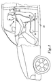
- FIG 1 schematically illustrates a seat belt arrangement 10 according to the invention when mounted in a vehicle having a vehicle body and a seat.
- the seat belt arrangement comprises a seat belt 12, a lower seat belt anchor 14 and an upper seat belt anchor 16.
- the seat belt anchors 14, 16 are utilized to attach end portions 18, 20 of the seat belt 12 to the vehicle body 22 or to the seat 24.
- the lower end portion 18 is attached to the seat 24 by the lower seat belt anchor 14, while the upper end portion 20 is attached to the vehicle body 22 by the upper seat belt anchor 16.
- One or both of the seat belt anchors 14, 16 may be configured according to the invention.
- the seat belt arrangement 10 may further comprise additional items, such as a buckle and a belt tensioning unit (not illustrated).
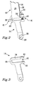
- FIGs 2 and 3 illustrate a detailed view of a seat belt anchor according to the invention, in this case the lower seat belt anchor 14.
- the seat belt anchor 14 comprises a first portion 26 and a second portion 28.
- the first portion 26 is directly attachable to the vehicle body 22 or to the seat 24, e.g. by means of a screw or a bolt and nut connection (not illustrated) through a hole 29 in the first portion 26.
- the second portion 28 comprises a passage 30, through which a seat belt portion is accommodated, here the lower end portion 18.
- the seat belt portion forms a loop 32.
- a part 34 of the second portion 28 of the seat belt anchor 14 passes through the loop 32, thereby attaching the lower end portion 18 of the seat belt 12 to the seat belt anchor 14.
- the loop 32 is closed by securing an end 36 of the end portion 18 to the seat belt 12 itself, e.g. by means of sewing or gluing. In the illustrated exemplary embodiment, there is an overlap 38 of a few centimetres, where the seat belt 12 is double, securing the loop 32.
- the passage 30 in the seat belt anchor 14 has an opening 40 at a lateral side 41.
- the opening 40 has a closed state wherein the opening 40 retains the seat belt portion 18 in the seat belt anchor 14, see Figure 2 , and an open state wherein the seat belt portion 18 may be inserted into the passage 40, see Figure 3 .
- the opening 40 can be closed by means of a closure member 42, e.g. a screw, a bolt, a pin or a clip.
- the loop 32 may easily be inserted through the opening 40 and threaded onto the part 34 of the second portion 28, such that the part 34 passes through the loop 32. Thereafter the opening 40 may be closed by the closure member 42 and the seat belt 12 is thereby securely attached to the seat belt anchor 14.
- the second portion 28 essentially has the form of a U, with two legs 44, 46 and an intermediate portion 48.
- the closure member 42 is attached between the ends of the legs 44, 46 of the U, such that the passage 30 is formed.
- the passage 30 has a closed circumference retaining the seat belt 12 in the seat belt anchor 14.
- the U is directed with its opening 40 at one of the lateral sides 41 of the second portion 28.
- the U may be directed in the lengthwise direction of the seat belt 12. In that case, the opening 40 would be at the top side of the second portion 28.
- FIGs. 1-3 illustrate an important advantage over conventional technology:
- the passage 30 does not have any opening. Therefore, the end 36 of the seat belt 12 must be inserted through the passage 30 and then folded backwards and secured to form the loop 32, i.e. first the seat belt is inserted through the passage and thereafter the loop 32 is formed. This is commonly done in a separate production line. Then the lower seat belt 14 is directly and fixedly attached to the seat 24 or the vehicle body 22, e.g. by means of a screw or bolt plus nut connection. However, since there is little free space around the first portion 26, it is difficult to access the screw or bolt in order to tighten it. Therefore, commonly a side panel, which normally covers the side and/or the frame of the seat 24, may have to be removed to gain access.
- the loop 32 is made in the seat belt 12.
- the seat belt 12 is, as a separate step, attached to the seat belt anchor 14 by inserting it through the opening 40 and threading the loop 32 over the part 34 of the second portion 28.
- the closure member 42 may instead be passed through the loop 32.
- the opening 40 is closed by the closure member 42, such that the seat belt 12 is retained by the seat belt anchor 14.
- the step of attaching of the seat belt anchor 14 to the vehicle body 22 or seat 24 is independent of the step of attaching the seat belt 12 to the seat belt anchor 14, and these two steps may be carried out in an arbitrary order.
- the seat belt 12 is fastened from above to a seat belt anchor 14 being pre-assembled in the vehicle body 22 or to the seat 24. If the seat belt anchor 14 is pre-assembled, there is accordingly adequate space to attach and secure it in an appropriate way, e.g. with suitable tools. Since the seat belt 12 is attached from above with the seat 24 being located in the vehicle, there is available space above the seat belt anchor 14. As a comparison, according to conventional technology, there may be a need to remove the side panel.
- a production data system may be used to log that screws, bolts etc are accurately attached, e.g. by measuring the torsional moment used.
- the production data system may be used to afterwards recall production data.
- the logging is especially important for the attachment of safety arrangements, such as a seat belt arrangement 10.
- the attachment of the seat belt 12 to the seat belt anchor 14 by closing the closure member 42 may be made on the production line and thereby be logged by the production system.
- Figs. 1 to 3 illustrate that the seat belt anchor 14 is attached to an end portion 18, 20 of the seat belt 12, it is also possible to attach the seat belt to the seat belt anchor anywhere along the seat belt 12. In that case, the seat belt 12 itself may pass through the passage 30 and no loop 32 would need to be formed.
- the enclosed embodiments illustrate the seat belt anchor and the seat belt arrangement in a vehicle, such as a car, they may also be used in other vehicles, such as a bus, lorry or truck, or vessels, such as an aircraft, a train or a boat.
Landscapes
- Engineering & Computer Science (AREA)
- Mechanical Engineering (AREA)
- Automotive Seat Belt Assembly (AREA)
Priority Applications (1)
| Application Number | Priority Date | Filing Date | Title |
|---|---|---|---|
| EP20100163476 EP2388166B1 (de) | 2010-05-20 | 2010-05-20 | Sitzgurtbefestigung |
Applications Claiming Priority (1)
| Application Number | Priority Date | Filing Date | Title |
|---|---|---|---|
| EP20100163476 EP2388166B1 (de) | 2010-05-20 | 2010-05-20 | Sitzgurtbefestigung |
Publications (2)
| Publication Number | Publication Date |
|---|---|
| EP2388166A1 true EP2388166A1 (de) | 2011-11-23 |
| EP2388166B1 EP2388166B1 (de) | 2013-07-17 |
Family
ID=42790674
Family Applications (1)
| Application Number | Title | Priority Date | Filing Date |
|---|---|---|---|
| EP20100163476 Not-in-force EP2388166B1 (de) | 2010-05-20 | 2010-05-20 | Sitzgurtbefestigung |
Country Status (1)
| Country | Link |
|---|---|
| EP (1) | EP2388166B1 (de) |
Citations (6)
| Publication number | Priority date | Publication date | Assignee | Title |
|---|---|---|---|---|
| GB1172778A (en) * | 1967-08-11 | 1969-12-03 | F D T S Ltd | Improvements in or relating to Restraining Straps. |
| FR2723556A1 (fr) * | 1994-08-10 | 1996-02-16 | Peugeot | Dispositif de reglage de la longueur d'une sangle a boucle de verrouillage d'une ceinture de securite de vehicule automobile. |
| DE19915275A1 (de) * | 1999-04-03 | 2000-10-05 | Volkswagen Ag | Sicherheitsgurtanordnung mit individuellen Gurtautomaten für Schulter- und Beckengurt |
| EP1557327A1 (de) * | 2004-01-21 | 2005-07-27 | Key Safety Systems, Inc. | Schnalle |
| US20060279130A1 (en) | 2005-06-10 | 2006-12-14 | Webber James L | Apparatus and method for attaching seat belt components |
| EP1918164A1 (de) * | 2006-10-30 | 2008-05-07 | Key Safety Systems, Inc. | Vorrichtung zur stufenweisen Höhenverstellung eines Sicherheitsgurtes |
-
2010
- 2010-05-20 EP EP20100163476 patent/EP2388166B1/de not_active Not-in-force
Patent Citations (6)
| Publication number | Priority date | Publication date | Assignee | Title |
|---|---|---|---|---|
| GB1172778A (en) * | 1967-08-11 | 1969-12-03 | F D T S Ltd | Improvements in or relating to Restraining Straps. |
| FR2723556A1 (fr) * | 1994-08-10 | 1996-02-16 | Peugeot | Dispositif de reglage de la longueur d'une sangle a boucle de verrouillage d'une ceinture de securite de vehicule automobile. |
| DE19915275A1 (de) * | 1999-04-03 | 2000-10-05 | Volkswagen Ag | Sicherheitsgurtanordnung mit individuellen Gurtautomaten für Schulter- und Beckengurt |
| EP1557327A1 (de) * | 2004-01-21 | 2005-07-27 | Key Safety Systems, Inc. | Schnalle |
| US20060279130A1 (en) | 2005-06-10 | 2006-12-14 | Webber James L | Apparatus and method for attaching seat belt components |
| EP1918164A1 (de) * | 2006-10-30 | 2008-05-07 | Key Safety Systems, Inc. | Vorrichtung zur stufenweisen Höhenverstellung eines Sicherheitsgurtes |
Also Published As
| Publication number | Publication date |
|---|---|
| EP2388166B1 (de) | 2013-07-17 |
Similar Documents
| Publication | Publication Date | Title |
|---|---|---|
| US8764360B2 (en) | Strap connector | |
| US8245994B2 (en) | Seat apparatus for vehicle | |
| US20090218789A1 (en) | Low movement trailer hitch | |
| US8615847B2 (en) | Direct acting clock spring counterbalanced hinge assembly | |
| US9151088B2 (en) | Door striker positioner | |
| CN1149158C (zh) | 带有用于安全肩带和安全腰带的独立的自动拉紧装置的安全带装置 | |
| CA2907828C (en) | Tow adapter | |
| US8960707B2 (en) | Pivoting tow hook | |
| EP2054246B1 (de) | Stossfängerstange für ein fahrzeug | |
| JP4809050B2 (ja) | 鉄道車両の車体構造 | |
| JP2008007044A (ja) | 牽引フックの取付構造 | |
| DE102020121791A1 (de) | Sicherungs- und flaschenöffnungssystem für ein fahrzeug | |
| EP2388166A1 (de) | Sitzgurtbefestigung | |
| US8096596B2 (en) | Bumper beam for a vehicle | |
| JP6459523B2 (ja) | エアバッグ装置 | |
| CN201552529U (zh) | 紧绳装置 | |
| JP3696554B2 (ja) | 車両用リトラクタ取付構造 | |
| US20200238889A1 (en) | Angled tie down anchors | |
| CN102781736B (zh) | 安全带附连夹和方法 | |
| CN211530619U (zh) | 扎带和线束固定组件 | |
| EP2918456B1 (de) | Klammer und Befestigungsanordnung | |
| US20150232306A1 (en) | Breakaway winch bracket and method of mounting same | |
| CN2803637Y (zh) | 捆绑器的棘轮 | |
| JP2013136323A (ja) | シートベルトリトラクタの取付構造 | |
| US20130264446A1 (en) | Clamp type retractor attachment |
Legal Events
| Date | Code | Title | Description |
|---|---|---|---|
| AK | Designated contracting states |
Kind code of ref document: A1 Designated state(s): AL AT BE BG CH CY CZ DE DK EE ES FI FR GB GR HR HU IE IS IT LI LT LU LV MC MK MT NL NO PL PT RO SE SI SK SM TR |
|
| AX | Request for extension of the european patent |
Extension state: BA ME RS |
|
| PUAI | Public reference made under article 153(3) epc to a published international application that has entered the european phase |
Free format text: ORIGINAL CODE: 0009012 |
|
| 17P | Request for examination filed |
Effective date: 20120523 |
|
| 17Q | First examination report despatched |
Effective date: 20121023 |
|
| GRAP | Despatch of communication of intention to grant a patent |
Free format text: ORIGINAL CODE: EPIDOSNIGR1 |
|
| INTG | Intention to grant announced |
Effective date: 20130404 |
|
| GRAS | Grant fee paid |
Free format text: ORIGINAL CODE: EPIDOSNIGR3 |
|
| GRAA | (expected) grant |
Free format text: ORIGINAL CODE: 0009210 |
|
| AK | Designated contracting states |
Kind code of ref document: B1 Designated state(s): AL AT BE BG CH CY CZ DE DK EE ES FI FR GB GR HR HU IE IS IT LI LT LU LV MC MK MT NL NO PL PT RO SE SI SK SM TR |
|
| REG | Reference to a national code |
Ref country code: GB Ref legal event code: FG4D |
|
| REG | Reference to a national code |
Ref country code: CH Ref legal event code: EP |
|
| REG | Reference to a national code |
Ref country code: IE Ref legal event code: FG4D |
|
| REG | Reference to a national code |
Ref country code: AT Ref legal event code: REF Ref document number: 621981 Country of ref document: AT Kind code of ref document: T Effective date: 20130815 |
|
| REG | Reference to a national code |
Ref country code: DE Ref legal event code: R096 Ref document number: 602010008559 Country of ref document: DE Effective date: 20130912 |
|
| REG | Reference to a national code |
Ref country code: SE Ref legal event code: TRGR |
|
| REG | Reference to a national code |
Ref country code: AT Ref legal event code: MK05 Ref document number: 621981 Country of ref document: AT Kind code of ref document: T Effective date: 20130717 |
|
| REG | Reference to a national code |
Ref country code: NL Ref legal event code: VDEP Effective date: 20130717 |
|
| REG | Reference to a national code |
Ref country code: LT Ref legal event code: MG4D |
|
| PG25 | Lapsed in a contracting state [announced via postgrant information from national office to epo] |
Ref country code: CY Free format text: LAPSE BECAUSE OF FAILURE TO SUBMIT A TRANSLATION OF THE DESCRIPTION OR TO PAY THE FEE WITHIN THE PRESCRIBED TIME-LIMIT Effective date: 20130731 Ref country code: IS Free format text: LAPSE BECAUSE OF FAILURE TO SUBMIT A TRANSLATION OF THE DESCRIPTION OR TO PAY THE FEE WITHIN THE PRESCRIBED TIME-LIMIT Effective date: 20131117 Ref country code: LT Free format text: LAPSE BECAUSE OF FAILURE TO SUBMIT A TRANSLATION OF THE DESCRIPTION OR TO PAY THE FEE WITHIN THE PRESCRIBED TIME-LIMIT Effective date: 20130717 Ref country code: PT Free format text: LAPSE BECAUSE OF FAILURE TO SUBMIT A TRANSLATION OF THE DESCRIPTION OR TO PAY THE FEE WITHIN THE PRESCRIBED TIME-LIMIT Effective date: 20131118 Ref country code: AT Free format text: LAPSE BECAUSE OF FAILURE TO SUBMIT A TRANSLATION OF THE DESCRIPTION OR TO PAY THE FEE WITHIN THE PRESCRIBED TIME-LIMIT Effective date: 20130717 Ref country code: NO Free format text: LAPSE BECAUSE OF FAILURE TO SUBMIT A TRANSLATION OF THE DESCRIPTION OR TO PAY THE FEE WITHIN THE PRESCRIBED TIME-LIMIT Effective date: 20131017 Ref country code: BE Free format text: LAPSE BECAUSE OF FAILURE TO SUBMIT A TRANSLATION OF THE DESCRIPTION OR TO PAY THE FEE WITHIN THE PRESCRIBED TIME-LIMIT Effective date: 20130717 Ref country code: HR Free format text: LAPSE BECAUSE OF FAILURE TO SUBMIT A TRANSLATION OF THE DESCRIPTION OR TO PAY THE FEE WITHIN THE PRESCRIBED TIME-LIMIT Effective date: 20130717 |
|
| PG25 | Lapsed in a contracting state [announced via postgrant information from national office to epo] |
Ref country code: SI Free format text: LAPSE BECAUSE OF FAILURE TO SUBMIT A TRANSLATION OF THE DESCRIPTION OR TO PAY THE FEE WITHIN THE PRESCRIBED TIME-LIMIT Effective date: 20130717 Ref country code: LV Free format text: LAPSE BECAUSE OF FAILURE TO SUBMIT A TRANSLATION OF THE DESCRIPTION OR TO PAY THE FEE WITHIN THE PRESCRIBED TIME-LIMIT Effective date: 20130717 Ref country code: FI Free format text: LAPSE BECAUSE OF FAILURE TO SUBMIT A TRANSLATION OF THE DESCRIPTION OR TO PAY THE FEE WITHIN THE PRESCRIBED TIME-LIMIT Effective date: 20130717 Ref country code: NL Free format text: LAPSE BECAUSE OF FAILURE TO SUBMIT A TRANSLATION OF THE DESCRIPTION OR TO PAY THE FEE WITHIN THE PRESCRIBED TIME-LIMIT Effective date: 20130717 Ref country code: GR Free format text: LAPSE BECAUSE OF FAILURE TO SUBMIT A TRANSLATION OF THE DESCRIPTION OR TO PAY THE FEE WITHIN THE PRESCRIBED TIME-LIMIT Effective date: 20131018 Ref country code: PL Free format text: LAPSE BECAUSE OF FAILURE TO SUBMIT A TRANSLATION OF THE DESCRIPTION OR TO PAY THE FEE WITHIN THE PRESCRIBED TIME-LIMIT Effective date: 20130717 Ref country code: ES Free format text: LAPSE BECAUSE OF FAILURE TO SUBMIT A TRANSLATION OF THE DESCRIPTION OR TO PAY THE FEE WITHIN THE PRESCRIBED TIME-LIMIT Effective date: 20131028 |
|
| PG25 | Lapsed in a contracting state [announced via postgrant information from national office to epo] |
Ref country code: CY Free format text: LAPSE BECAUSE OF FAILURE TO SUBMIT A TRANSLATION OF THE DESCRIPTION OR TO PAY THE FEE WITHIN THE PRESCRIBED TIME-LIMIT Effective date: 20130717 |
|
| PG25 | Lapsed in a contracting state [announced via postgrant information from national office to epo] |
Ref country code: EE Free format text: LAPSE BECAUSE OF FAILURE TO SUBMIT A TRANSLATION OF THE DESCRIPTION OR TO PAY THE FEE WITHIN THE PRESCRIBED TIME-LIMIT Effective date: 20130717 Ref country code: RO Free format text: LAPSE BECAUSE OF FAILURE TO SUBMIT A TRANSLATION OF THE DESCRIPTION OR TO PAY THE FEE WITHIN THE PRESCRIBED TIME-LIMIT Effective date: 20130717 Ref country code: DK Free format text: LAPSE BECAUSE OF FAILURE TO SUBMIT A TRANSLATION OF THE DESCRIPTION OR TO PAY THE FEE WITHIN THE PRESCRIBED TIME-LIMIT Effective date: 20130717 Ref country code: CZ Free format text: LAPSE BECAUSE OF FAILURE TO SUBMIT A TRANSLATION OF THE DESCRIPTION OR TO PAY THE FEE WITHIN THE PRESCRIBED TIME-LIMIT Effective date: 20130717 Ref country code: SK Free format text: LAPSE BECAUSE OF FAILURE TO SUBMIT A TRANSLATION OF THE DESCRIPTION OR TO PAY THE FEE WITHIN THE PRESCRIBED TIME-LIMIT Effective date: 20130717 |
|
| PLBE | No opposition filed within time limit |
Free format text: ORIGINAL CODE: 0009261 |
|
| STAA | Information on the status of an ep patent application or granted ep patent |
Free format text: STATUS: NO OPPOSITION FILED WITHIN TIME LIMIT |
|
| PG25 | Lapsed in a contracting state [announced via postgrant information from national office to epo] |
Ref country code: IT Free format text: LAPSE BECAUSE OF FAILURE TO SUBMIT A TRANSLATION OF THE DESCRIPTION OR TO PAY THE FEE WITHIN THE PRESCRIBED TIME-LIMIT Effective date: 20130717 |
|
| 26N | No opposition filed |
Effective date: 20140422 |
|
| REG | Reference to a national code |
Ref country code: DE Ref legal event code: R097 Ref document number: 602010008559 Country of ref document: DE Effective date: 20140422 |
|
| PG25 | Lapsed in a contracting state [announced via postgrant information from national office to epo] |
Ref country code: LU Free format text: LAPSE BECAUSE OF FAILURE TO SUBMIT A TRANSLATION OF THE DESCRIPTION OR TO PAY THE FEE WITHIN THE PRESCRIBED TIME-LIMIT Effective date: 20140520 |
|
| REG | Reference to a national code |
Ref country code: CH Ref legal event code: PL |
|
| PG25 | Lapsed in a contracting state [announced via postgrant information from national office to epo] |
Ref country code: MC Free format text: LAPSE BECAUSE OF FAILURE TO SUBMIT A TRANSLATION OF THE DESCRIPTION OR TO PAY THE FEE WITHIN THE PRESCRIBED TIME-LIMIT Effective date: 20130717 Ref country code: LI Free format text: LAPSE BECAUSE OF NON-PAYMENT OF DUE FEES Effective date: 20140531 Ref country code: CH Free format text: LAPSE BECAUSE OF NON-PAYMENT OF DUE FEES Effective date: 20140531 |
|
| REG | Reference to a national code |
Ref country code: IE Ref legal event code: MM4A |
|
| REG | Reference to a national code |
Ref country code: FR Ref legal event code: ST Effective date: 20150130 |
|
| PG25 | Lapsed in a contracting state [announced via postgrant information from national office to epo] |
Ref country code: IE Free format text: LAPSE BECAUSE OF NON-PAYMENT OF DUE FEES Effective date: 20140520 |
|
| PG25 | Lapsed in a contracting state [announced via postgrant information from national office to epo] |
Ref country code: FR Free format text: LAPSE BECAUSE OF NON-PAYMENT OF DUE FEES Effective date: 20140602 |
|
| PG25 | Lapsed in a contracting state [announced via postgrant information from national office to epo] |
Ref country code: MT Free format text: LAPSE BECAUSE OF FAILURE TO SUBMIT A TRANSLATION OF THE DESCRIPTION OR TO PAY THE FEE WITHIN THE PRESCRIBED TIME-LIMIT Effective date: 20130717 |
|
| PG25 | Lapsed in a contracting state [announced via postgrant information from national office to epo] |
Ref country code: SM Free format text: LAPSE BECAUSE OF FAILURE TO SUBMIT A TRANSLATION OF THE DESCRIPTION OR TO PAY THE FEE WITHIN THE PRESCRIBED TIME-LIMIT Effective date: 20130717 |
|
| PG25 | Lapsed in a contracting state [announced via postgrant information from national office to epo] |
Ref country code: BG Free format text: LAPSE BECAUSE OF FAILURE TO SUBMIT A TRANSLATION OF THE DESCRIPTION OR TO PAY THE FEE WITHIN THE PRESCRIBED TIME-LIMIT Effective date: 20130717 |
|
| PG25 | Lapsed in a contracting state [announced via postgrant information from national office to epo] |
Ref country code: HU Free format text: LAPSE BECAUSE OF FAILURE TO SUBMIT A TRANSLATION OF THE DESCRIPTION OR TO PAY THE FEE WITHIN THE PRESCRIBED TIME-LIMIT; INVALID AB INITIO Effective date: 20100520 Ref country code: TR Free format text: LAPSE BECAUSE OF FAILURE TO SUBMIT A TRANSLATION OF THE DESCRIPTION OR TO PAY THE FEE WITHIN THE PRESCRIBED TIME-LIMIT Effective date: 20130717 |
|
| PG25 | Lapsed in a contracting state [announced via postgrant information from national office to epo] |
Ref country code: MK Free format text: LAPSE BECAUSE OF FAILURE TO SUBMIT A TRANSLATION OF THE DESCRIPTION OR TO PAY THE FEE WITHIN THE PRESCRIBED TIME-LIMIT Effective date: 20130717 |
|
| PG25 | Lapsed in a contracting state [announced via postgrant information from national office to epo] |
Ref country code: AL Free format text: LAPSE BECAUSE OF FAILURE TO SUBMIT A TRANSLATION OF THE DESCRIPTION OR TO PAY THE FEE WITHIN THE PRESCRIBED TIME-LIMIT Effective date: 20130717 |
|
| PGFP | Annual fee paid to national office [announced via postgrant information from national office to epo] |
Ref country code: SE Payment date: 20190515 Year of fee payment: 10 |
|
| PGFP | Annual fee paid to national office [announced via postgrant information from national office to epo] |
Ref country code: GB Payment date: 20190508 Year of fee payment: 10 |
|
| PG25 | Lapsed in a contracting state [announced via postgrant information from national office to epo] |
Ref country code: SE Free format text: LAPSE BECAUSE OF NON-PAYMENT OF DUE FEES Effective date: 20200521 |
|
| GBPC | Gb: european patent ceased through non-payment of renewal fee |
Effective date: 20200520 |
|
| PG25 | Lapsed in a contracting state [announced via postgrant information from national office to epo] |
Ref country code: GB Free format text: LAPSE BECAUSE OF NON-PAYMENT OF DUE FEES Effective date: 20200520 |
|
| P01 | Opt-out of the competence of the unified patent court (upc) registered |
Effective date: 20231212 |
|
| PGFP | Annual fee paid to national office [announced via postgrant information from national office to epo] |
Ref country code: DE Payment date: 20240418 Year of fee payment: 15 |
|
| REG | Reference to a national code |
Ref country code: DE Ref legal event code: R119 Ref document number: 602010008559 Country of ref document: DE |
|
| PG25 | Lapsed in a contracting state [announced via postgrant information from national office to epo] |
Ref country code: DE Free format text: LAPSE BECAUSE OF NON-PAYMENT OF DUE FEES Effective date: 20251202 |