EP2388193A2 - Système de guide pour ensemble formant nacelle - Google Patents
Système de guide pour ensemble formant nacelle Download PDFInfo
- Publication number
- EP2388193A2 EP2388193A2 EP11250493A EP11250493A EP2388193A2 EP 2388193 A2 EP2388193 A2 EP 2388193A2 EP 11250493 A EP11250493 A EP 11250493A EP 11250493 A EP11250493 A EP 11250493A EP 2388193 A2 EP2388193 A2 EP 2388193A2
- Authority
- EP
- European Patent Office
- Prior art keywords
- track
- assembly
- slider
- nacelle
- liner
- Prior art date
- Legal status (The legal status is an assumption and is not a legal conclusion. Google has not performed a legal analysis and makes no representation as to the accuracy of the status listed.)
- Granted
Links
Images




Classifications
-
- B—PERFORMING OPERATIONS; TRANSPORTING
- B64—AIRCRAFT; AVIATION; COSMONAUTICS
- B64D—EQUIPMENT FOR FITTING IN OR TO AIRCRAFT; FLIGHT SUITS; PARACHUTES; ARRANGEMENT OR MOUNTING OF POWER PLANTS OR PROPULSION TRANSMISSIONS IN AIRCRAFT
- B64D33/00—Arrangement in aircraft of power plant parts or auxiliaries not otherwise provided for
- B64D33/04—Arrangement in aircraft of power plant parts or auxiliaries not otherwise provided for of exhaust outlets or jet pipes
-
- B—PERFORMING OPERATIONS; TRANSPORTING
- B64—AIRCRAFT; AVIATION; COSMONAUTICS
- B64D—EQUIPMENT FOR FITTING IN OR TO AIRCRAFT; FLIGHT SUITS; PARACHUTES; ARRANGEMENT OR MOUNTING OF POWER PLANTS OR PROPULSION TRANSMISSIONS IN AIRCRAFT
- B64D29/00—Power-plant nacelles, fairings or cowlings
- B64D29/06—Attaching of nacelles, fairings or cowlings
-
- F—MECHANICAL ENGINEERING; LIGHTING; HEATING; WEAPONS; BLASTING
- F02—COMBUSTION ENGINES; HOT-GAS OR COMBUSTION-PRODUCT ENGINE PLANTS
- F02K—JET-PROPULSION PLANTS
- F02K1/00—Plants characterised by the form or arrangement of the jet pipe or nozzle; Jet pipes or nozzles peculiar thereto
- F02K1/06—Varying effective area of jet pipe or nozzle
- F02K1/08—Varying effective area of jet pipe or nozzle by axially moving or transversely deforming an internal member, e.g. the exhaust cone
-
- F—MECHANICAL ENGINEERING; LIGHTING; HEATING; WEAPONS; BLASTING
- F02—COMBUSTION ENGINES; HOT-GAS OR COMBUSTION-PRODUCT ENGINE PLANTS
- F02K—JET-PROPULSION PLANTS
- F02K1/00—Plants characterised by the form or arrangement of the jet pipe or nozzle; Jet pipes or nozzles peculiar thereto
- F02K1/06—Varying effective area of jet pipe or nozzle
- F02K1/09—Varying effective area of jet pipe or nozzle by axially moving an external member, e.g. a shroud
-
- F—MECHANICAL ENGINEERING; LIGHTING; HEATING; WEAPONS; BLASTING
- F02—COMBUSTION ENGINES; HOT-GAS OR COMBUSTION-PRODUCT ENGINE PLANTS
- F02K—JET-PROPULSION PLANTS
- F02K1/00—Plants characterised by the form or arrangement of the jet pipe or nozzle; Jet pipes or nozzles peculiar thereto
- F02K1/54—Nozzles having means for reversing jet thrust
- F02K1/56—Reversing jet main flow
- F02K1/62—Reversing jet main flow by blocking the rearward discharge by means of flaps
- F02K1/625—Reversing jet main flow by blocking the rearward discharge by means of flaps the aft end of the engine cowling being movable to uncover openings for the reversed flow
-
- F—MECHANICAL ENGINEERING; LIGHTING; HEATING; WEAPONS; BLASTING
- F02—COMBUSTION ENGINES; HOT-GAS OR COMBUSTION-PRODUCT ENGINE PLANTS
- F02K—JET-PROPULSION PLANTS
- F02K1/00—Plants characterised by the form or arrangement of the jet pipe or nozzle; Jet pipes or nozzles peculiar thereto
- F02K1/54—Nozzles having means for reversing jet thrust
- F02K1/64—Reversing fan flow
- F02K1/70—Reversing fan flow using thrust reverser flaps or doors mounted on the fan housing
- F02K1/72—Reversing fan flow using thrust reverser flaps or doors mounted on the fan housing the aft end of the fan housing being movable to uncover openings in the fan housing for the reversed flow
-
- F—MECHANICAL ENGINEERING; LIGHTING; HEATING; WEAPONS; BLASTING
- F02—COMBUSTION ENGINES; HOT-GAS OR COMBUSTION-PRODUCT ENGINE PLANTS
- F02K—JET-PROPULSION PLANTS
- F02K1/00—Plants characterised by the form or arrangement of the jet pipe or nozzle; Jet pipes or nozzles peculiar thereto
- F02K1/54—Nozzles having means for reversing jet thrust
- F02K1/76—Control or regulation of thrust reversers
- F02K1/763—Control or regulation of thrust reversers with actuating systems or actuating devices; Arrangement of actuators for thrust reversers
-
- Y—GENERAL TAGGING OF NEW TECHNOLOGICAL DEVELOPMENTS; GENERAL TAGGING OF CROSS-SECTIONAL TECHNOLOGIES SPANNING OVER SEVERAL SECTIONS OF THE IPC; TECHNICAL SUBJECTS COVERED BY FORMER USPC CROSS-REFERENCE ART COLLECTIONS [XRACs] AND DIGESTS
- Y02—TECHNOLOGIES OR APPLICATIONS FOR MITIGATION OR ADAPTATION AGAINST CLIMATE CHANGE
- Y02T—CLIMATE CHANGE MITIGATION TECHNOLOGIES RELATED TO TRANSPORTATION
- Y02T50/00—Aeronautics or air transport
- Y02T50/60—Efficient propulsion technologies, e.g. for aircraft
Definitions
- the present invention generally relates to gas turbine aircraft engines, and particularly relates to a guide system for a translating thrust reverser and a translating variable area nozzle assembly for a turbofan aircraft engine for use in selectively controlling the fan bypass flow exhausted from the engine in order to adjust the engine's performance under varying flight conditions.
- Typical aircraft turbofan jet engines include a fan that draws and directs a flow of air into a nacelle and into and around an engine core.
- the nacelle surrounds the engine core and helps promote the laminar flow of air around the core.
- the flow of air that is directed into the engine core is initially passed-through a compressor that increases the air flow pressure, and then through a combustor where the air is mixed with fuel and ignited.
- the combustion of the fuel and air mixture causes a series of turbine blades at the rear of the engine core to rotate, and to drive the engine's rotor and fan.
- the high-pressure exhaust gases from the combustion of the fuel and air mixture are thereafter directed through an exhaust nozzle at the rear of the engine.
- bypass flow is air that is directed around the engine core.
- the bypass flow typically provides the main thrust for an aircraft.
- the bypass flow also can be used to help slow a landed aircraft.
- Translatable thrust reversers mounted in the nacelle structure selectively reverse the direction of the bypass flow to generate reverse thrust.
- the thrust reverser is translatable via a guide system directed by an actuation device.
- turbofan engine parameters are important to optimize design characteristics and performance.
- One design consideration for optimizing such parameters includes varying the fan nozzle exit area of a high-bypass ration (BPR) engine during operation by translating the engine's variable fan nozzle to optimize engine performance under various flight conditions. By selectively varying the fan nozzle's exit area, an engine's bypass flow characteristics can be adjusted to match a particular flight condition.
- One way of varying the fan nozzle exit area involves using a translating sleeve to increase or decrease the exit area. Providing a translating sleeve requires a guide system that properly considers surrounding reacting loads (inboard, outboard, and radial) and efficiently manages contact stresses. Also, translating guide systems require a design to minimize seizing of translating components during use.
- the invention includes a guide system for translating components of an aircraft engine nacelle.
- the guide system includes a track assembly adapted to operably engage a first portion of a nacelle.
- the track assembly includes a track guide member and a track liner operably engaged therewith.
- the track guide member has a track channel configured to receive the track liner.
- the track liner defines an interior surface and has a projection portion projecting inwardly of the track channel to define a convex surface.
- the guide system further includes a slider assembly configured to translatably engage the track assembly.
- the slider assembly includes a slider member having a head portion configured to be received within the track channel.
- the head portion defines a concave surface substantially corresponding to the convex surface of the track liner and is configured to mate therewith.
- the slider member further includes an extension portion extending from the head portion and outwardly of the track assembly.
- the invention also includes a nacelle assembly for a turbofan aircraft engine having a first and second nacelle portion.
- the nacelle assembly further includes a track assembly operably engaged with the first nacelle portion.
- the track assembly includes a track guide member and a track liner operably engaged therewith.
- the track guide member has a track channel configured to receive the track liner.
- the track liner defines an interior surface and has a projection portion projecting inwardly of the track channel to define a convex surface.
- the nacelle assembly further includes a slider assembly configured to translatably engage the track assembly.
- the slider assembly includes a slider member having a head portion configured to be received within the track channel.
- the head portion defines a concave surface substantially corresponding to the convex surface of the track liner and is configured to mate therewith.
- the slider member further has an extension portion extending from the head portion and outwardly of the track assembly.
- the second nacelle portion is operably engaged with the extension portion of the slider member.
- a nacelle assembly in another embodiment, includes a stationary first nacelle portion.
- a stationary track assembly is operably engaged with the stationary first nacelle portion.
- the track assembly includes a track guide member and a track liner operably engaged therewith.
- the track guide member has a track channel configured to receive the track liner.
- the track liner defines an interior surface and has a projection portion projecting inwardly of the track channel to define a convex surface.
- the nacelle assembly further includes means for slidably engaging one of a translatable variable area fan nozzle section and a translatable thrust reverser sleeve to the stationary track assembly.
- the means for slidably engaging the one of a translatable variable area fan nozzle section and a translatable thrust reverser sleeve includes a concave portion substantially corresponding to the convex portion of the track assembly.
- the concave portion is configured to correspondingly mate with the convex portion.
- the nacelle assembly further includes means for actuating the means for slidably engaging the one of a translatable variable area fan nozzle section and a translatable thrust reverser sleeve.
- FIG. 1 is a perspective view of an aircraft engine having a cascade-type thrust reverser and a translating variable area fan nozzle assembly;
- FIG. 2 is a longitudinal cross section of the aircraft engine shown in FIG.1 ;
- FIG. 3 is a rear elevation view of the aircraft engine shown in FIGS. 1-2 ;
- FIG. 4 is a perspective view of the thrust reverser and translating variable area fan nozzle assembly portions of the aircraft engine shown in FIGS. 1-3 with a thrust reverser sleeve in a stowed position, and a variable area fan nozzle in a deployed position;
- FIG. 5 is a perspective view of the thrust reverser and translating variable area fan nozzle assembly shown in FIG. 4 with both the thrust reverser sleeve and the variable area fan nozzle in deployed positions;
- FIG. 6 is an exploded perspective view of the thrust reverser and translating variable area fan nozzle assembly shown in FIGS. 4-5 ;
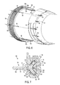
- FIG. 7 is a cross sectional view of a guide structure for movably supporting a thrust reverser sleeve or a variable area fan nozzle section, according to one embodiment of the present invention.
- FIG. 8 is a perspective view of the guide system shown in FIG. 7 ;
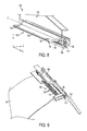
- FIG. 9 is a perspective view of a portion of a variable area fan nozzle section coupled to a guide system in accordance with one embodiment of the present invention.
- FIG. 10A is an end view of a track assembly of a guide system in accordance with one embodiment of the present invention.
- FIG. 10B is a perspective view of a portion of a track assembly of a guide system with a track liner removed therefrom;
- FIG. 10C is a perspective view of a portion of a track assembly of a guide system having a track liner, according to one embodiment of the present invention.
- FIGS. 11A-11C are end views of a guide system in accordance with one embodiment of the present invention, illustrating the guide system reacting to various loads;
- FIGS. 12A-12C are end views of a guide system in accordance with one embodiment of the present invention, illustrating the rotation of a slider assembly of the guide system;
- FIGS. 13A-13D are various views of a guide system and its components according to one embodiment of the present invention, wherein the guide system includes a slider assembly and a track assembly having a bearing layer applied thereto; and
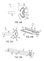
- FIGS. 14A-14D are various views of a guide system and its components according to another embodiment of the present invention, wherein the guide system includes a track assembly and a slider assembly having a bearing layer applied thereto.
- FIGS. 1-6 show one embodiment of a translating variable area fan nozzle assembly (VAFN) for a turbofan engine 10.
- VAFN translating variable area fan nozzle assembly
- the engine 10 includes a fan nozzle assembly 12 having a translating nozzle 50 that can be selectively adjusted, for example, as the engine 10 operates under different flight conditions. As discussed above, such an adjustment can be used to optimize an engine's performance. As shown in FIG. 2 , the translating nozzle 50 can be selectively translated (i.e., moved fore and aft) to vary the fan nozzle's exit area " A exit " in order to optimize engine performance, and as described in detail below, to adjust an amount of engine bypass flow spilled through an upstream exit 60 formed by the variable area fan nozzle assembly 12.
- variable area fan nozzle assembly 12 is shown in the context of a turbofan jet aircraft engine 10.
- the engine 10 can be mounted to a wing or fuselage of an aircraft, for example, by a pylon or other similar support (not shown in the figures).
- the engine 10 includes an engine core 16 and a stationary nacelle 18 surrounding the core 16.
- the engine core 16 is housed within a core cowl 19.
- the engine's fan 20 is positioned within an upstream portion of the nacelle 18, and includes a plurality of fan blades 22 that are mounted on the engine's rotor (not shown).
- the fan blades 22 rotate about the engine's centerline C L and draw a flow of air into an inlet end 26 of the engine 10.
- An annular bypass duct 24 is defined between the engine core 16 and the nacelle 18. The air flow drawn into the engine 10 is accelerated by the rotating fan blades 22, and a portion of the incoming air flow is directed into and through the engine core 16.
- bypass flow enters the upstream end of the nacelle 18 and flows around and past the engine core 16.
- the bypass flow is accelerated by the rotating fan blades 22 and passes through the bypass duct 24 and past stators 40, and exits the engine 10 through the variable area fan nozzle assembly 12.
- the high-pressure heated exhaust gases from the combustion of the fuel and air mixture exit the engine core 16 through a primary exhaust nozzle 13 at the aft end of the engine 10.
- the translating nozzle 50 can be a nozzle-like annular airfoil structure mounted at the trailing end of a cascade-type thrust reverser 80 that circumscribes the engine core cowl 19 at the aft end of the nacelle 18.
- a downstream nozzle exit 52 between the trailing edge of the fan nozzle 50 and the core cowl 19 defines a fan nozzle exit area " A exit ". Due to the longitudinal variations in the diameter of the core cowl 19, selective fore and aft movement of the translating nozzle 50 changes the size of the fan nozzle exit area A exit .
- FIG. 1 Due to the longitudinal variations in the diameter of the core cowl 19, selective fore and aft movement of the translating nozzle 50 changes the size of the fan nozzle exit area A exit .
- the fan nozzle 50 can include a first arcuate nozzle section 54 and a second arcuate nozzle section 56, each nozzle section 54, 56 being axially translatable in the direction of the bidirectional arrow 58.
- Translation of the translating nozzle 50 effects a desired size of the upstream exit 60, and also varies the outlet geometry and effective exit area A exit of the downstream nozzle exit 52.
- bypass air is discharged from the engine assembly 10 through both the upstream exit 60 and the enlarged downstream nozzle exit 52.
- the translating nozzle 50 can be selectively translated fore and aft by a plurality of linear nozzle actuators 70, for example.
- the cascade-type thrust reverser 80 can be positioned forward of the translating nozzle 50 in order to selectively block and redirect bypass flow from the bypass duct 24 in a manner known in the art.
- the thrust reverser 80 and the translating nozzle 50 are both in their stowed positions.
- the thrust reverser 80 can include a first arcuate sleeve section 82 and an opposed second arcuate sleeve section 84 (shown in FIG. 3 ).
- the thrust reverser sleeve sections 82, 84 can be translated in the fore and aft directions by a plurality of spaced sleeve actuators 90.
- the thrust reverser sleeve sections 82, 84 cover an array of cascade vanes 88.
- the cascade vanes 88 are indicated under the cut-away section of the sleeve section 82.
- Axial translation of the thrust reverser sleeve sections 82, 84 in the aft direction to a deployed position and deployment of a series of blocker doors (not shown) within the bypass duct 24 causes bypass air flow to exit the bypass duct 24 through the cascade vanes 88 which turn the exiting flow in a generally forward direction to create reverse thrust.
- FIG. 3 is a partial section view of the aft end of the engine 10, and illustrates one arrangement of the nozzle and sleeve actuators 70, 90, respectively, around the periphery of the engine 10.
- the sleeve half section 82 and the nozzle half-section 54 cooperate to generally define an approximately 180-degree sector of the combined thrust reverser and translating nozzle structure.
- sleeve half section 84 and nozzle half section 56 cooperate to generally define an opposed approximately 180-degree sector of the thrust reverser and translating nozzle structure. Together, these approximate 180-degree sectors cooperate to define the complete thrust reverser/translating nozzle structure.
- the thrust reverser sleeve sections 82, 84 can each be selectively translated in the fore and aft directions by one or more circumferentially spaced sleeve actuators 90 that are connected to the nacelle 18.
- three actuators 90 are used for each sleeve half-section 82, 84.
- each section 54, 56 of the translating nozzle 50 can be selectively translated by one or more circumferentially spaced nozzle actuators 70.
- each nozzle actuator 70 is disposed between a thrust reverser sleeve section 82, 84 and a respective fan nozzle section 54, 56.
- the sleeve actuators 90 and the nozzle actuators 70 can be electrical, mechanical, pneumatic, hydraulic, or the like, and can be interconnected by appropriate power cables and conduits (not shown).
- the number and arrangement of nozzle and sleeve actuators 70, 90 can vary according to the thrust reverser and nozzle assembly configurations or other factors.
- FIG. 3 shows a detailed view of one embodiment of a guide system 102.
- guide tubes 104 can be mounted to the nacelle 18, and can extend into the nozzle sections 54, 56 to stabilize the nozzle sections 54, 56 against undesirable translation and/or vibration.
- the guide tubes 104 can each include an elongated slider that translates within the tube (not shown in the figures), for example.
- the translating nozzle 50 can include arcuate nozzle sections 54, 56 having airfoil profiles.
- the upstream exit 60 shown in FIG. 2 is formed when the translating nozzle 50 is deployed in the aft direction (i.e., away from the fixed thrust reverser sleeve sections 82, 84), and can have the form of a generally circular annular gap.
- the upstream exit 60 can have a non-circular shape.
- the gap 60 between the nozzle sections 54, 56 and the sleeve sections 82, 84 can be continuous, or can be interrupted at one or more locations, such as, for example, at points of separation between nozzle segments 54, 56 of the translating nozzle 50.
- FIGS. 4-7 elements that are obscured or partially obscured due to intervening elements are indicated by dashed lead lines.
- FIG. 4 is a partial view of one embodiment of a mounting structure for a first nozzle section 54 of the translating nozzle 50 and the corresponding, adjacent first sleeve section 82 of the thrust reverser 80.
- the second nozzle section 56 of the translating nozzle 50 and the second sleeve section 84 of the thrust reverser 80 can be mounted in a similar manner.
- the thrust reverser 80 is shown in a stowed position, and the first sleeve section 82 covers an associated portion of the cascade vanes 88. Also in FIG.
- the translating nozzle 50 is in an open or deployed position, which results in formation of the upstream exit 60 between the first nozzle section 54 and the first sleeve section 82.
- Rearward axial translation of the first nozzle section 54 from its stowed position to its deployed position is indicated in FIGS. 4-5 by directional arrow "X".
- the nozzle actuators 70 can extend from the sleeve section 82 and across the upstream exit 60, and can connect to a forward portion of the nozzle section 54.
- the guide tubes 104 can also extend from the sleeve section 82 and across the upstream exit 60, and can connect to a forward portion of the nozzle section 54.
- a flexible shaft 96 can interconnect two or more of the sleeve actuators 90 to power the actuators 90, and/or to synchronize actuation of two or more actuators 90.
- FIG. 5 shows the first thrust reverser sleeve section 82 and the first translating nozzle section 54 in their deployed positions, for illustrative purposes.
- Rearward axial translation of the first sleeve section 82 from its stowed position (as shown in FIG. 4 ) to its deployed position (as shown in FIG. 5 ) is indicated in FIG. 5 by directional arrow "Y".
- Rearward translation of the sleeve section 82 exposes the cascade vanes 88 during operation of the thrust reverser 80.
- FIG. 6 is an exploded view showing the first sleeve section 82 and its corresponding first nozzle section 54 separated from the cascades 88 and sleeve actuators 90. As shown in FIG. 6 , one or more nozzle actuators 70 can movably connect the nozzle section 54 to the thrust reverser sleeve section 82.
- FIG. 7 shows one embodiment of the upper or lower guide system 102 for movably connecting a thrust reverser segment 82 or a nozzle section 54 to an engine 10.
- the guide system 102 can include a track assembly 106 and a slider assembly 150. Either assembly can be held stationary while the other translates, although the track assembly 106 is stationary in a preferred embodiment.
- the guide system 102 can include the track assembly 106 coupled to a beam 120 that can be fixedly attached to a transverse bulkhead 110 on an aft end of a nacelle 18. As shown in FIG.
- the track assembly 106 can include one or more longitudinally extending track guide members 108, such as, for example, a primary track guide member 108a and a supplemental track guide member 108b.
- Each track guide member 108 can define a longitudinally extending track channel 110, such as, for example, a primary track channel 110a and a supplemental track channel 110b.
- the primary track guide member 108a and the supplemental track guide member 108b may be arranged in parallel so as to facilitate corresponding translation of slider assemblies engaged therewith.
- the guide system 102 can further include the slider assembly 150 configured to slidably engage the track assembly 106.
- the slider assembly 150 can include one or more longitudinally extending slider members 152 that are slidably received within the track channels 110 of the track assembly 106.
- the slider assembly 150 may be connected to the thrust reverser sleeve section 82 so as to slidably connect the sleeve section to the beam 120.
- the slider assembly 150 may be connected to the nozzle section 54 to slidably connect the nozzle section 54 to the nacelle 18. Accordingly, the nozzle section 54 or the thrust reverser sleeve section 82 can axially translate as the slider member 152 slides within the track channel 110.
- the nozzle section 54 can be thereby slidably mounted with respect to the sleeve section 82 of the thrust reverser 80.
- the translating sleeve section 82 or the translating nozzle section 54 can be actuated through conventional actuation means, such as mechanical, electric, hydraulic or pneumatic or other equivalent actuators, for example.
- the nozzle actuator 70 is a constant opening air spring damper with hydraulic closing override
- the sleeve actuator 90 is an electric actuator.
- one or more of the actuators 70, 90 can be like an actuator described in U.S. Patent No. 7,174,828 or in U.S. Patent Application Publication No. 2008/0084130A1 , both assigned to Goodrich Actuation Systems Ltd., for example, the disclosures of which are hereby incorporated by reference.
- the track assembly 106 includes the track guide member 108, which includes the track channel 110.
- the track assembly 106 can further include a track liner 112 disposed within the track channel 110, and the track liner 112 may be permanently or temporarily fixed to the track guide member 108 using appropriate methods, e.g., fasteners, adhesives, etc.
- the track liner 112 may be integrally formed with the track guide member 108 as a single piece.
- the track liner 112 may include a plurality of fastener apertures 114 (shown in FIGS.
- the track guide member 108 may include a plurality of associated apertures 116 in corresponding alignment with the fastener apertures 114, thereby permitting a fastener 200 to extend through the track liner 112 and into the track guide member 108 so as to couple the track liner 112 and the track guide member 108 (see FIGS. 10A and 10B ).
- an insert member 250 may be positioned within the apertures 116 of the track guide member 108 to provide a complementary fastening mechanism to the fastener 200.
- the length of the fastener may be such that the head 202 thereof may be advanced into the track liner 112 so as not to interrupt or otherwise obstruct the path of the slider member 152 within the track channel 110. See FIG. 10A .
- An exterior surface 118 of the track liner 112 may substantially correspond with an interior surface 109 of the track guide member 108.
- the track liner 112 can include a projection portion 120 projecting inwardly of the track channel 110 to define a convex surface 122 in the embodiment shown in FIG. 7 .
- the track liner 112 further can define a pair of cylindrical liner surfaces 124 concentric to the convex surface 122 of the track liner 112. That is, the cylindrical liner surfaces 124 and the convex surface 122 share the same central axis.
- the track guide member 108 is open-ended by defining an elongated opening or slot 170. In this regard, the cylindrical liner surfaces 124 are discontinuous due to the slot 170. Integrally transitioning the cylindrical liner surface 124 to the convex surface 122 is a pair of arcuate liner surface portions 126 defined by the track liner 112.
- the interior surface of the track liner 112 may be smooth to provide a sliding surface, and, in some instances, the interior surface may have a hard coating applied thereto for improving durability.
- Preferred materials for the track liner may include, for example, aluminum and steel, and preferred coatings include aluminum oxide formed during hard anodizing (aluminum applications).
- a track bearing layer 400 may be applied to the interior surface of the track liner 112 to facilitate sliding of the slider assembly 150 or the track assembly 106. ( FIGS. 11A-11C ). In such instances, the slider member 152 may or may not also include a slider bearing layer 450 ( FIGS. 14A - 14C).
- the track bearing layer 400 and slider bearing layer 450 may comprise a low friction bearing material such as, for example, self-lubricating liner systems such as KARON (available from Kamatics Corporation), durable high-performance polymide-based polymers such as VESPEL (available from DuPont), and self-lubricating composites such as RULON (available from Saint-Gobain Performance Plastics).
- KARON available from Kamatics Corporation
- VESPEL durable high-performance polymide-based polymers
- RULON self-lubricating composites
- the slider member 152 can include a head portion 154 and an extension portion 156 extending therefrom.
- the head portion 152 is disposed within the track channel 110 and the extension portion 156 extends outwardly of the track assembly 106 through the elongate slot 170.
- the spacing S of the slot 170 is greater than the thickness T of the extension portion 156 so as to allow rotation of the slider member 152 along an arcuate path R.
- the slider member 152 may rotate between about +/- 5 degrees with respect to a longitudinal axis Z ( FIG. 8 ) of the track guide member 108.
- the extension portion 156 may include a plurality of apertures 158 for receiving fasteners 210 ( FIG.
- the head portion 154 substantially corresponds to the track liner 112, wherein the head portion 154 has as substantially C-shaped cross-section.
- the head portion 154 defines a concave surface 160 substantially corresponding to the convex surface 122 of the track liner 112 so as to substantially mate therewith.
- the head portion 154 further defines a pair of cylindrical slider surfaces 162 concentric to the concave surface 160 thereof. That is, the cylindrical slider surfaces 162 and the concave surface 160 share the same central axis. Extending from the head portion 154, the extension portion 156 creates a discontinuity between the slider surfaces 162. Accordingly, the cylindrical liner surface 124 and the cylindrical slider surface 162 are capable of interacting within the track channel 110.
- the concave surface 160 and the cylindrical slider surface 162 may be integrally connected or otherwise transitioned in a continuous manner by a pair of arcuate slider surface portions 164.
- the radius of the concave surface 160 of the head portion 154 of the slider member 152 is equal to or slightly greater than the radius of the convex surface 122 of the projection portion 120 of the track liner 112.
- the exterior surface of the slider member 152 may be smooth to provide a sliding surface, and, in some instances, the exterior surface may have a hard coating applied thereto for improving durability.
- Preferred materials for the slider member may include, for example, aluminum, steel, titanium, and preferred coatings include aluminum oxide formed during hard anodizing (aluminum applications).
- the slider assembly 150 may further include an actuator fitting assembly 166 ( FIG. 9 ) attached to or otherwise integral with the extension portion 156, wherein the actuator fitting assembly 166 is configured to receive an actuator device capable of translating the slider assembly 150 in the fore and aft directions, as previously described.
- an actuator fitting assembly 166 FIG. 9
- FIGS. 11A-11C illustrate the manner in which the guide system 102 operates under various loads according to one embodiment of the invention.
- the guide system 102 substantially constrains the slider assembly 150 in the X and Y directions while allowing the slider assembly 150 to translate along the Z axis.
- the guide system 102 also constrains the slider assembly 150 about the X and Y axes while allowing limited rotation about the Z axis.
- the guide system 102 may be tailored for various applied loads.
- the slider member 152 is tensioned such that the extension portion 156 is pulled outward of the track guide member 108.
- each cylindrical slider surface 162 may include a large radius to allow for greater contact area with the track liner 112 so as to lower contact stress, thereby reducing wear and extending the life of the guide system 102. Furthermore, a large radius reduces the angle of the normal force N, which results in lower friction and less force required for translation.
- the liner surface 124 and the slider surface 162 may have substantially the same radius so as to correspondingly match. Such a configuration may lead to low contact stress and thus reduce wear and extend the life of the guide system 102.
- the radius of the slider surface 162 may be smaller than the radius of the liner surface 124, thereby moving the contact area close to a neck portion 155 (where the head portion 154 and the extension portion 156 meet) of the slider member 152, which can result in lower normal forces and thus reduced friction.
- the radius of the concave surface 160 may be greater than the radius of the convex surface 122.
- FIG. 11A illustrates the guide system 102 reacting a load L1.
- the head portion 154 of the slider member 152 and the track liner 112 of the track guide member 108 contact and interface at a contact portion C1 proximate to an upper portion of the convex surface 122 and the concave surface 160.
- FIG. 11B illustrates the guide system 102 reacting a compression load L2.
- the head portion 154 of the slider member 152 and the track liner 112 of the track guide member 108 contact and interface at a contact portion C2 at a central portion of the convex surface 122 and the concave surface 160.
- FIG. 11C illustrates the guide system 102 reacting to an outward radial load L3.
- the head portion 154 of the slider member 152 and the track liner 112 of the track guide member 108 contact and interface at contact portions C3 at a lower portion of the convex surface 122 and the concave surface 160, as well as at an upper portion of the cylindrical liner surface 124 (or bearing member 400) and the cylindrical slider surface 162.
- FIGS. 12A-12C illustrate the rotation of the slider assembly 150 within the track channel 110.
- the slider assembly 150 can be prevented from further rotation by one of the arcuate slider surface portions 164 contacting or otherwise interacting with one of the arcuate liner surfaces 126, as shown in FIGS. 12A and 12B .
- FIGS. 13A-13D show one embodiment of the guide system 102 and its components, wherein a bearing material is provided on the track liner 112 as the track bearing layer 400 (shown in hatching). That is, the bearing material is provided on the track assembly 106, rather than on the slider assembly 150.
- FIGS. 14A-14D show another embodiment of the guide system 102 and its components, wherein a bearing material is provided on the head portion 154 of the slider member 152 as the slider bearing layer 450 (shown in hatching).
- the bearing material is provided on the slider assembly 150, rather than the track assembly 106.
- the bearing material may be a low friction bearing material or any other suitable bearing materials, such as, for example, self-lubricating liner systems such as KARON (available from Kamatics Corporation), durable high-performance polymide-based polymers such as VESPEL (available from DuPont), and self-lubricating composites such as RULON (available from Saint-Gobain Performance Plastics).
Landscapes
- Engineering & Computer Science (AREA)
- Chemical & Material Sciences (AREA)
- Combustion & Propulsion (AREA)
- Mechanical Engineering (AREA)
- General Engineering & Computer Science (AREA)
- Aviation & Aerospace Engineering (AREA)
- Structures Of Non-Positive Displacement Pumps (AREA)
- Turbine Rotor Nozzle Sealing (AREA)
Applications Claiming Priority (1)
| Application Number | Priority Date | Filing Date | Title |
|---|---|---|---|
| US12/781,242 US8875486B2 (en) | 2010-05-17 | 2010-05-17 | Guide system for nacelle assembly |
Publications (3)
| Publication Number | Publication Date |
|---|---|
| EP2388193A2 true EP2388193A2 (fr) | 2011-11-23 |
| EP2388193A3 EP2388193A3 (fr) | 2014-07-09 |
| EP2388193B1 EP2388193B1 (fr) | 2018-04-25 |
Family
ID=44118378
Family Applications (1)
| Application Number | Title | Priority Date | Filing Date |
|---|---|---|---|
| EP11250493.1A Active EP2388193B1 (fr) | 2010-05-17 | 2011-04-26 | Système de guide pour ensemble formant nacelle |
Country Status (3)
| Country | Link |
|---|---|
| US (1) | US8875486B2 (fr) |
| EP (1) | EP2388193B1 (fr) |
| CN (1) | CN102278231B (fr) |
Cited By (2)
| Publication number | Priority date | Publication date | Assignee | Title |
|---|---|---|---|---|
| GB2529681A (en) * | 2014-08-29 | 2016-03-02 | Rolls Royce Plc | Gas turbine engine rotor arrangement |
| FR3140069A1 (fr) * | 2022-09-22 | 2024-03-29 | Safran Nacelles | Ensemble de guidage pour un ensemble propulsif d’aeronef |
Families Citing this family (42)
| Publication number | Priority date | Publication date | Assignee | Title |
|---|---|---|---|---|
| FR2954278B1 (fr) * | 2009-12-18 | 2012-01-20 | Aircelle 7303 | Structure support pour inverseur de poussee notamment a grilles |
| FR2968635B1 (fr) * | 2010-12-14 | 2012-12-14 | Aircelle Sa | Nacelle pour turboreacteur d’aeronef double flux |
| US8727275B2 (en) | 2012-01-27 | 2014-05-20 | Rohr, Inc. | Nacelle |
| FR2995876B1 (fr) * | 2012-07-24 | 2019-05-03 | Rohr, Inc | Tuyere de soufflante a section variable et inverseur de poussee integres |
| US9989009B2 (en) * | 2012-10-31 | 2018-06-05 | The Boeing Company | Methods and apparatus for sealing variable area fan nozzles of jet engines |
| FR2997925B1 (fr) * | 2012-11-09 | 2016-03-04 | Aircelle Sa | Ensemble de guidage pour ensemble unitaire mobile de nacelle pour turboreacteur |
| FR2999239B1 (fr) * | 2012-12-12 | 2015-02-20 | Aircelle Sa | Inverseur de poussee de nacelle et nacelle equipee d'au moins un inverseur |
| CN103112595B (zh) * | 2013-02-06 | 2016-01-27 | 中国商用飞机有限责任公司 | 推进系统一体化的吊挂结构 |
| US10240561B2 (en) * | 2013-03-15 | 2019-03-26 | United Technologies Corporation | Aerodynamic track fairing for a gas turbine engine fan nacelle |
| DE102013006109A1 (de) * | 2013-04-09 | 2014-10-09 | Rolls-Royce Deutschland Ltd & Co Kg | Antriebsvorrichtung einer variablen Ausströmdüse eines Fluggasturbinentriebwerks |
| US10040563B1 (en) * | 2013-04-11 | 2018-08-07 | Geoffrey P. Pinto | Dual panel actuator system for jet engines |
| US10289761B1 (en) | 2013-06-12 | 2019-05-14 | The United States Of America, As Represented By The Secretary Of The Navy | Method for modeling dynamic trajectories of guided, self-propelled moving bodies |
| US9388768B2 (en) * | 2013-08-23 | 2016-07-12 | Rohr, Inc. | Blocker door actuation system and apparatus |
| US9739235B2 (en) * | 2014-03-21 | 2017-08-22 | Rohr, Inc. | Thrust reverser for a turbofan engine |
| US20160076450A1 (en) * | 2014-04-21 | 2016-03-17 | Bob Burkett | Solar Jet Turbofan Aircraft Engine |
| US9869275B2 (en) * | 2014-04-24 | 2018-01-16 | Rohr, Inc. | Single actuator variable area fan nozzle system and method |
| US9869190B2 (en) | 2014-05-30 | 2018-01-16 | General Electric Company | Variable-pitch rotor with remote counterweights |
| US10012175B2 (en) * | 2014-05-30 | 2018-07-03 | The Boeing Company | Thrust reverser torque box with discrete major fittings |
| US10161356B2 (en) * | 2014-06-02 | 2018-12-25 | Ge Aviation Systems Llc | Integrated thrust reverser actuation system |
| FR3023324B1 (fr) * | 2014-07-01 | 2020-04-24 | Safran Nacelles | Inverseur de poussee d’une nacelle de turboreacteur, comprenant des decoupes d’evitement du bec mobile de l’aile |
| DE102014221052A1 (de) * | 2014-10-16 | 2016-04-21 | Premium Aerotec Gmbh | Fluggasturbinenschubumkehrvorrichtung mit Führungsschiene |
| US10309343B2 (en) * | 2014-11-06 | 2019-06-04 | Rohr, Inc. | Split sleeve hidden door thrust reverser |
| US10072510B2 (en) | 2014-11-21 | 2018-09-11 | General Electric Company | Variable pitch fan for gas turbine engine and method of assembling the same |
| US10030608B2 (en) | 2015-05-15 | 2018-07-24 | Rohr Inc. | Variable area fan nozzle actuation system |
| US10100653B2 (en) | 2015-10-08 | 2018-10-16 | General Electric Company | Variable pitch fan blade retention system |
| CN106627446B (zh) * | 2015-10-30 | 2019-05-07 | 长城汽车股份有限公司 | 车辆机舱管路布置结构及车辆 |
| US10730636B2 (en) * | 2016-07-18 | 2020-08-04 | Rolls-Royce North American Technologies Inc. | Integrated aircraft cooling system |
| US10543927B2 (en) * | 2016-11-18 | 2020-01-28 | Rohr, Inc. | Lockable track system for a translating nacelle structure |
| FR3059299B1 (fr) * | 2016-11-30 | 2021-11-12 | Safran Nacelles | Nacelle de turboreacteur d’aeronef, ensemble propulsif et aeronef comportant une telle nacelle |
| US11022071B2 (en) * | 2016-12-21 | 2021-06-01 | The Boeing Company | Load distribution panel assembly, system and method |
| FR3075760B1 (fr) * | 2017-12-21 | 2020-01-31 | Safran Nacelles | Nacelle de moteur d’aeronef |
| CN113492988B (zh) * | 2020-04-02 | 2023-06-20 | 中国航发商用航空发动机有限责任公司 | 反推力装置和航空发动机 |
| EP3943737B1 (fr) * | 2020-04-07 | 2025-08-20 | Rohr, Inc. | Système inverseur de poussée à volet caché pour système de propulsion d'aéronef |
| CN114718758B (zh) * | 2021-01-05 | 2023-10-31 | 中国航发商用航空发动机有限责任公司 | 反推装置、滑动配合件及其成形方法 |
| FR3119648B1 (fr) * | 2021-02-05 | 2023-01-27 | Safran Nacelles | Inverseur de poussée comprenant des grilles et des capots mobiles assemblés par embrèvement |
| US11674435B2 (en) | 2021-06-29 | 2023-06-13 | General Electric Company | Levered counterweight feathering system |
| US11795964B2 (en) | 2021-07-16 | 2023-10-24 | General Electric Company | Levered counterweight feathering system |
| US11754019B2 (en) | 2021-12-17 | 2023-09-12 | Rohr, Inc. | Articulating slider for nacelle |
| CN114715416B (zh) * | 2022-03-22 | 2025-08-12 | 中国商用飞机有限责任公司北京民用飞机技术研究中心 | 一种航空涡扇发动机及外涵道喷口 |
| CN114526175B (zh) * | 2022-04-24 | 2022-07-26 | 中国航发四川燃气涡轮研究院 | 一种用于加力燃烧室的齿轮传动后涵道引射器 |
| US12601271B2 (en) | 2022-10-21 | 2026-04-14 | General Electric Company | Variable pitch fan of a gas turbine engine |
| US12152551B1 (en) | 2024-01-12 | 2024-11-26 | Rtx Corporation | Variable area nozzle for an aircraft engine |
Citations (2)
| Publication number | Priority date | Publication date | Assignee | Title |
|---|---|---|---|---|
| US7174828B2 (en) | 2004-06-02 | 2007-02-13 | Goodrich Actuation Systems Limited | Linear actuator |
| US20080084130A1 (en) | 2006-10-06 | 2008-04-10 | Goodrich Actuation Systems Limited | Actuator |
Family Cites Families (57)
| Publication number | Priority date | Publication date | Assignee | Title |
|---|---|---|---|---|
| GB841110A (en) | 1957-03-13 | 1960-07-13 | Rolls Royce | Improvements in or relating to jet propulsion nozzle arrangements |
| FR1260040A (fr) | 1960-03-07 | 1961-05-05 | Snecma | Dispositif déviateur de jet |
| US3360308A (en) | 1964-12-23 | 1967-12-26 | Gen Motors Corp | Actuator assembly |
| US3404581A (en) | 1967-04-18 | 1968-10-08 | Sargent Industries | Ball screw actuator |
| GB1365491A (en) | 1971-01-02 | 1974-09-04 | Dowty Rotol Ltd | Gas turbine ducted fan engines and fans therefor |
| GB1418905A (en) | 1972-05-09 | 1975-12-24 | Rolls Royce | Gas turbine engines |
| US3779010A (en) | 1972-08-17 | 1973-12-18 | Gen Electric | Combined thrust reversing and throat varying mechanism for a gas turbine engine |
| AT335234B (de) * | 1975-09-24 | 1977-02-25 | Miba Gleitlager Ag | Gleitlager und verfahren zu seiner herstellung |
| US4375276A (en) | 1980-06-02 | 1983-03-01 | General Electric Company | Variable geometry exhaust nozzle |
| US4407120A (en) * | 1980-08-25 | 1983-10-04 | Rohr Industries, Inc. | Thrust reverser geared linkage |
| FR2496766A1 (fr) | 1980-12-23 | 1982-06-25 | Snecma | Dispositif de guidage de carenage mobile d'un systeme d'inversion de poussee |
| EP0109219A3 (fr) | 1982-11-12 | 1985-11-13 | LUCAS INDUSTRIES public limited company | Dispositif d'inversion de jet pour un moteur à turbine à gaz |
| US4519561A (en) | 1983-05-23 | 1985-05-28 | Rohr Industries, Inc. | Aircraft thrust reverser mechanism |
| FR2622929A1 (fr) | 1987-11-05 | 1989-05-12 | Hispano Suiza Sa | Inverseur de poussee de turboreacteur a grilles,a section variable d'ejection |
| US5174502A (en) * | 1991-05-10 | 1992-12-29 | General Electric Company | Support for a translating nozzle vectoring ring |
| US5228641A (en) | 1991-08-15 | 1993-07-20 | Rohr, Inc. | Cascade type aircraft engine thrust reverser with hidden link actuator |
| FR2680547B1 (fr) | 1991-08-21 | 1993-10-15 | Hispano Suiza | Inverseur de poussee de turboreacteur ayant un bord de deviation a courbure evolutive. |
| US5209057A (en) * | 1991-10-23 | 1993-05-11 | Rohr, Inc. | Rack and pinion actuation for an aircraft engine thrust reverser |
| US5285637A (en) * | 1992-11-02 | 1994-02-15 | United Technologies Corporation | Seal centering and restraining device for an axisymmetric convergent/divergent nozzle |
| US5328098A (en) * | 1993-07-09 | 1994-07-12 | United Technologies Corporation | Thrust vectoring ejector nozzle |
| GB9326466D0 (en) | 1993-12-24 | 1994-02-23 | Rolls Royce Plc | Thrust reverser control mechanism |
| US5778659A (en) * | 1994-10-20 | 1998-07-14 | United Technologies Corporation | Variable area fan exhaust nozzle having mechanically separate sleeve and thrust reverser actuation systems |
| US5575147A (en) | 1994-12-22 | 1996-11-19 | United Technologies Corporation | Compact thrust reverser |
| US5655360A (en) | 1995-05-31 | 1997-08-12 | General Electric Company | Thrust reverser with variable nozzle |
| JPH09195853A (ja) | 1995-12-14 | 1997-07-29 | United Technol Corp <Utc> | 可変面積ファンエキゾーストノズル |
| FR2745036B1 (fr) | 1996-02-15 | 1998-04-03 | Hispano Suiza Sa | Inverseur de poussee de turboreacteur a portes associees a un panneau amont |
| US5806302A (en) | 1996-09-24 | 1998-09-15 | Rohr, Inc. | Variable fan exhaust area nozzle for aircraft gas turbine engine with thrust reverser |
| FR2755730B1 (fr) | 1996-11-14 | 1999-01-08 | Hispano Suiza Sa | Systeme de commande electrique pour inverseur de poussee de turboreacteur |
| FR2764643B1 (fr) | 1997-06-12 | 1999-07-16 | Hispano Suiza Sa | Inverseur de poussee a portes de turboreacteur a section variable d'ejection |
| GB9825651D0 (en) | 1998-11-23 | 1999-01-13 | Lucas Ind Plc | Actuator |
| US6170254B1 (en) | 1998-12-18 | 2001-01-09 | Rohr, Inc. | Translating sleeve for cascade type thrust reversing system for fan gas turbine engine for an aircraft |
| GB2347126B (en) | 1999-02-23 | 2003-02-12 | Rolls Royce Plc | Thrust reverser |
| GB9911148D0 (en) | 1999-05-14 | 1999-07-14 | Lucas Ind Plc | Actuator |
| US6199772B1 (en) * | 1999-08-25 | 2001-03-13 | General Electric Company | Linear actuation and vectoring ring support mechanism for axisymmetric vectoring nozzle |
| US6439504B1 (en) | 2001-06-15 | 2002-08-27 | Honeywell International, Inc. | System and method for sustaining electric power during a momentary power interruption in an electric thrust reverser actuation system |
| US6845945B1 (en) | 2001-07-20 | 2005-01-25 | Aircraft Integration Resources, Inc. | Thrust reverser with sliding pivot joints |
| US6681559B2 (en) | 2001-07-24 | 2004-01-27 | Honeywell International, Inc. | Thrust reverser position determination system and method |
| US6625972B1 (en) * | 2001-08-30 | 2003-09-30 | The Boeing Company | Thrust reverser sleeve lock |
| US6968675B2 (en) | 2002-10-29 | 2005-11-29 | Rohr, Inc. | Cascadeless fan thrust reverser with plume control |
| US6824101B2 (en) * | 2003-02-17 | 2004-11-30 | The Boeing Company | Apparatus and method for mounting a cascade support ring to a thrust reverser |
| US6976352B2 (en) | 2003-03-22 | 2005-12-20 | The Nordam Group, Inc. | Toggle interlocked thrust reverser |
| FR2866020B1 (fr) | 2004-02-10 | 2006-06-16 | Rocco Compagnone | Systeme de structures telescopiques mises en oeuvre par une serie de verin a vis |
| US7096661B2 (en) * | 2004-03-26 | 2006-08-29 | United Technologies Corporation | Axial divergent section slot nozzle |
| AT503290B1 (de) | 2006-06-23 | 2007-09-15 | Fischer Adv Components Gmbh | Führungsträger für triebwerksverkleidungen |
| US20080010969A1 (en) | 2006-07-11 | 2008-01-17 | Thomas Anthony Hauer | Gas turbine engine and method of operating same |
| US8104261B2 (en) | 2006-10-12 | 2012-01-31 | United Technologies Corporation | Tri-body variable area fan nozzle and thrust reverser |
| FR2907512B1 (fr) | 2006-10-23 | 2008-12-12 | Aircelle Sa | Inverseur de poussee a grilles pour moteur a reaction |
| FR2912189B1 (fr) | 2007-02-01 | 2012-02-17 | Airbus France | Nacelle d'aeronef incorporant un dispositif pour inverser la poussee |
| GB0706270D0 (en) | 2007-03-30 | 2007-05-09 | Goodrich Actuation Systems Ltd | Actuator arrangement |
| FR2914700B1 (fr) * | 2007-04-04 | 2009-05-22 | Aircelle Sa | Inverseur de poussee pour moteur a reaction |
| FR2917788B1 (fr) | 2007-06-19 | 2009-07-24 | Aircelle Sa | Actionneur double action a effet programme |
| EP2479414B1 (fr) | 2007-08-08 | 2015-06-10 | Rohr, Inc. | Tuyère de soufflante à surface variable avec flux de dérivation |
| US8074440B2 (en) | 2007-08-23 | 2011-12-13 | United Technologies Corporation | Gas turbine engine with axial movable fan variable area nozzle |
| FR2922059B1 (fr) | 2007-10-04 | 2014-07-04 | Aircelle Sa | Actionneur lineaire telescopique double action a systeme d'entrainement a moteur unique |
| FR2921976B1 (fr) | 2007-10-08 | 2009-12-04 | Aircelle Sa | Actionneur pour structure mobile de nacelle d'aeronef, et nacelle comprenant au moins un tel actionneur |
| US8006479B2 (en) | 2007-10-15 | 2011-08-30 | United Technologies Corporation | Thrust reversing variable area nozzle |
| EP2075417B1 (fr) * | 2007-12-27 | 2016-04-06 | Techspace Aero | Plateforme pour une roue aubagée de turbomachine, roue aubagée et compresseur ou turbomachine comportant une telle roue aubagée |
-
2010
- 2010-05-17 US US12/781,242 patent/US8875486B2/en active Active
-
2011
- 2011-04-26 EP EP11250493.1A patent/EP2388193B1/fr active Active
- 2011-05-16 CN CN201110126044.5A patent/CN102278231B/zh not_active Expired - Fee Related
Patent Citations (2)
| Publication number | Priority date | Publication date | Assignee | Title |
|---|---|---|---|---|
| US7174828B2 (en) | 2004-06-02 | 2007-02-13 | Goodrich Actuation Systems Limited | Linear actuator |
| US20080084130A1 (en) | 2006-10-06 | 2008-04-10 | Goodrich Actuation Systems Limited | Actuator |
Cited By (6)
| Publication number | Priority date | Publication date | Assignee | Title |
|---|---|---|---|---|
| GB2529681A (en) * | 2014-08-29 | 2016-03-02 | Rolls Royce Plc | Gas turbine engine rotor arrangement |
| US10119425B2 (en) | 2014-08-29 | 2018-11-06 | Rolls-Royce Plc | Gas turbine engine rotor arrangement |
| GB2529681B (en) * | 2014-08-29 | 2019-02-20 | Rolls Royce Plc | Gas turbine engine rotor arrangement |
| FR3140069A1 (fr) * | 2022-09-22 | 2024-03-29 | Safran Nacelles | Ensemble de guidage pour un ensemble propulsif d’aeronef |
| US12372045B2 (en) | 2022-09-22 | 2025-07-29 | Safran Nacelles | Guide assembly for an aircraft propulsion unit |
| FR3158708A1 (fr) * | 2022-09-22 | 2025-08-01 | Safran Nacelles | Ensemble de guidage pour un ensemble propulsif d’aeronef |
Also Published As
| Publication number | Publication date |
|---|---|
| US20110277448A1 (en) | 2011-11-17 |
| EP2388193A3 (fr) | 2014-07-09 |
| EP2388193B1 (fr) | 2018-04-25 |
| CN102278231A (zh) | 2011-12-14 |
| US8875486B2 (en) | 2014-11-04 |
| CN102278231B (zh) | 2015-05-20 |
Similar Documents
| Publication | Publication Date | Title |
|---|---|---|
| EP2388193B1 (fr) | Système de guide pour ensemble formant nacelle | |
| EP2399827B1 (fr) | Système de guide pour ensemble formant nacelle | |
| US8505307B2 (en) | Translating variable area fan nozzle with split beavertail fairings | |
| EP2837810B1 (fr) | Unité à inversion de poussée | |
| US10174715B2 (en) | Gas turbine engine with axial movable fan variable area nozzle | |
| US8869507B2 (en) | Translatable cascade thrust reverser | |
| US9551298B2 (en) | Variable area fan nozzle with one or more integrated blocker doors | |
| US9759087B2 (en) | Translating variable area fan nozzle providing an upstream bypass flow exit | |
| US8074440B2 (en) | Gas turbine engine with axial movable fan variable area nozzle | |
| EP2278146B1 (fr) | Système d'actionnement pour moduler une zone variable de buse de ventilateur | |
| EP2278147B1 (fr) | Modulation de buse de ventilation à fente variable fournissant une sortie de dérivation d'écoulement en amont | |
| EP2239449B1 (fr) | Ensemble de nacelle pour moteurs d'avion à réacteur à double flux | |
| EP2788609A1 (fr) | Moteur à turbine à gaz possédant une buse à surface variable de ventilateur mobile axialement | |
| US11802523B2 (en) | Multi-lobed bullnose ramp | |
| EP4012170B1 (fr) | Rampe arrondie multilobes |
Legal Events
| Date | Code | Title | Description |
|---|---|---|---|
| 17P | Request for examination filed |
Effective date: 20110510 |
|
| AK | Designated contracting states |
Kind code of ref document: A2 Designated state(s): AL AT BE BG CH CY CZ DE DK EE ES FI FR GB GR HR HU IE IS IT LI LT LU LV MC MK MT NL NO PL PT RO RS SE SI SK SM TR |
|
| AX | Request for extension of the european patent |
Extension state: BA ME |
|
| PUAI | Public reference made under article 153(3) epc to a published international application that has entered the european phase |
Free format text: ORIGINAL CODE: 0009012 |
|
| PUAL | Search report despatched |
Free format text: ORIGINAL CODE: 0009013 |
|
| AK | Designated contracting states |
Kind code of ref document: A3 Designated state(s): AL AT BE BG CH CY CZ DE DK EE ES FI FR GB GR HR HU IE IS IT LI LT LU LV MC MK MT NL NO PL PT RO RS SE SI SK SM TR |
|
| AX | Request for extension of the european patent |
Extension state: BA ME |
|
| RIC1 | Information provided on ipc code assigned before grant |
Ipc: F02K 1/72 20060101ALI20140603BHEP Ipc: F02K 1/62 20060101ALI20140603BHEP Ipc: B64D 29/06 20060101AFI20140603BHEP Ipc: F02K 1/76 20060101ALI20140603BHEP Ipc: F02K 1/09 20060101ALI20140603BHEP Ipc: F02K 1/08 20060101ALI20140603BHEP Ipc: B64D 33/04 20060101ALI20140603BHEP |
|
| GRAP | Despatch of communication of intention to grant a patent |
Free format text: ORIGINAL CODE: EPIDOSNIGR1 |
|
| STAA | Information on the status of an ep patent application or granted ep patent |
Free format text: STATUS: GRANT OF PATENT IS INTENDED |
|
| INTG | Intention to grant announced |
Effective date: 20171117 |
|
| GRAA | (expected) grant |
Free format text: ORIGINAL CODE: 0009210 |
|
| GRAS | Grant fee paid |
Free format text: ORIGINAL CODE: EPIDOSNIGR3 |
|
| STAA | Information on the status of an ep patent application or granted ep patent |
Free format text: STATUS: THE PATENT HAS BEEN GRANTED |
|
| AK | Designated contracting states |
Kind code of ref document: B1 Designated state(s): AL AT BE BG CH CY CZ DE DK EE ES FI FR GB GR HR HU IE IS IT LI LT LU LV MC MK MT NL NO PL PT RO RS SE SI SK SM TR |
|
| REG | Reference to a national code |
Ref country code: GB Ref legal event code: FG4D |
|
| REG | Reference to a national code |
Ref country code: CH Ref legal event code: EP |
|
| REG | Reference to a national code |
Ref country code: AT Ref legal event code: REF Ref document number: 992599 Country of ref document: AT Kind code of ref document: T Effective date: 20180515 |
|
| REG | Reference to a national code |
Ref country code: IE Ref legal event code: FG4D |
|
| REG | Reference to a national code |
Ref country code: FR Ref legal event code: PLFP Year of fee payment: 8 |
|
| REG | Reference to a national code |
Ref country code: DE Ref legal event code: R096 Ref document number: 602011047759 Country of ref document: DE |
|
| REG | Reference to a national code |
Ref country code: NL Ref legal event code: MP Effective date: 20180425 |
|
| REG | Reference to a national code |
Ref country code: LT Ref legal event code: MG4D |
|
| PG25 | Lapsed in a contracting state [announced via postgrant information from national office to epo] |
Ref country code: NL Free format text: LAPSE BECAUSE OF FAILURE TO SUBMIT A TRANSLATION OF THE DESCRIPTION OR TO PAY THE FEE WITHIN THE PRESCRIBED TIME-LIMIT Effective date: 20180425 |
|
| PG25 | Lapsed in a contracting state [announced via postgrant information from national office to epo] |
Ref country code: SE Free format text: LAPSE BECAUSE OF FAILURE TO SUBMIT A TRANSLATION OF THE DESCRIPTION OR TO PAY THE FEE WITHIN THE PRESCRIBED TIME-LIMIT Effective date: 20180425 Ref country code: LT Free format text: LAPSE BECAUSE OF FAILURE TO SUBMIT A TRANSLATION OF THE DESCRIPTION OR TO PAY THE FEE WITHIN THE PRESCRIBED TIME-LIMIT Effective date: 20180425 Ref country code: BG Free format text: LAPSE BECAUSE OF FAILURE TO SUBMIT A TRANSLATION OF THE DESCRIPTION OR TO PAY THE FEE WITHIN THE PRESCRIBED TIME-LIMIT Effective date: 20180725 Ref country code: FI Free format text: LAPSE BECAUSE OF FAILURE TO SUBMIT A TRANSLATION OF THE DESCRIPTION OR TO PAY THE FEE WITHIN THE PRESCRIBED TIME-LIMIT Effective date: 20180425 Ref country code: NO Free format text: LAPSE BECAUSE OF FAILURE TO SUBMIT A TRANSLATION OF THE DESCRIPTION OR TO PAY THE FEE WITHIN THE PRESCRIBED TIME-LIMIT Effective date: 20180725 Ref country code: ES Free format text: LAPSE BECAUSE OF FAILURE TO SUBMIT A TRANSLATION OF THE DESCRIPTION OR TO PAY THE FEE WITHIN THE PRESCRIBED TIME-LIMIT Effective date: 20180425 Ref country code: PL Free format text: LAPSE BECAUSE OF FAILURE TO SUBMIT A TRANSLATION OF THE DESCRIPTION OR TO PAY THE FEE WITHIN THE PRESCRIBED TIME-LIMIT Effective date: 20180425 |
|
| PG25 | Lapsed in a contracting state [announced via postgrant information from national office to epo] |
Ref country code: LV Free format text: LAPSE BECAUSE OF FAILURE TO SUBMIT A TRANSLATION OF THE DESCRIPTION OR TO PAY THE FEE WITHIN THE PRESCRIBED TIME-LIMIT Effective date: 20180425 Ref country code: GR Free format text: LAPSE BECAUSE OF FAILURE TO SUBMIT A TRANSLATION OF THE DESCRIPTION OR TO PAY THE FEE WITHIN THE PRESCRIBED TIME-LIMIT Effective date: 20180726 Ref country code: HR Free format text: LAPSE BECAUSE OF FAILURE TO SUBMIT A TRANSLATION OF THE DESCRIPTION OR TO PAY THE FEE WITHIN THE PRESCRIBED TIME-LIMIT Effective date: 20180425 Ref country code: RS Free format text: LAPSE BECAUSE OF FAILURE TO SUBMIT A TRANSLATION OF THE DESCRIPTION OR TO PAY THE FEE WITHIN THE PRESCRIBED TIME-LIMIT Effective date: 20180425 |
|
| REG | Reference to a national code |
Ref country code: CH Ref legal event code: PL |
|
| REG | Reference to a national code |
Ref country code: AT Ref legal event code: MK05 Ref document number: 992599 Country of ref document: AT Kind code of ref document: T Effective date: 20180425 |
|
| REG | Reference to a national code |
Ref country code: BE Ref legal event code: MM Effective date: 20180430 |
|
| PG25 | Lapsed in a contracting state [announced via postgrant information from national office to epo] |
Ref country code: PT Free format text: LAPSE BECAUSE OF FAILURE TO SUBMIT A TRANSLATION OF THE DESCRIPTION OR TO PAY THE FEE WITHIN THE PRESCRIBED TIME-LIMIT Effective date: 20180827 |
|
| REG | Reference to a national code |
Ref country code: IE Ref legal event code: MM4A |
|
| REG | Reference to a national code |
Ref country code: DE Ref legal event code: R097 Ref document number: 602011047759 Country of ref document: DE |
|
| PG25 | Lapsed in a contracting state [announced via postgrant information from national office to epo] |
Ref country code: MC Free format text: LAPSE BECAUSE OF FAILURE TO SUBMIT A TRANSLATION OF THE DESCRIPTION OR TO PAY THE FEE WITHIN THE PRESCRIBED TIME-LIMIT Effective date: 20180425 Ref country code: CZ Free format text: LAPSE BECAUSE OF FAILURE TO SUBMIT A TRANSLATION OF THE DESCRIPTION OR TO PAY THE FEE WITHIN THE PRESCRIBED TIME-LIMIT Effective date: 20180425 Ref country code: RO Free format text: LAPSE BECAUSE OF FAILURE TO SUBMIT A TRANSLATION OF THE DESCRIPTION OR TO PAY THE FEE WITHIN THE PRESCRIBED TIME-LIMIT Effective date: 20180425 Ref country code: SK Free format text: LAPSE BECAUSE OF FAILURE TO SUBMIT A TRANSLATION OF THE DESCRIPTION OR TO PAY THE FEE WITHIN THE PRESCRIBED TIME-LIMIT Effective date: 20180425 Ref country code: LU Free format text: LAPSE BECAUSE OF NON-PAYMENT OF DUE FEES Effective date: 20180426 Ref country code: EE Free format text: LAPSE BECAUSE OF FAILURE TO SUBMIT A TRANSLATION OF THE DESCRIPTION OR TO PAY THE FEE WITHIN THE PRESCRIBED TIME-LIMIT Effective date: 20180425 Ref country code: AT Free format text: LAPSE BECAUSE OF FAILURE TO SUBMIT A TRANSLATION OF THE DESCRIPTION OR TO PAY THE FEE WITHIN THE PRESCRIBED TIME-LIMIT Effective date: 20180425 Ref country code: DK Free format text: LAPSE BECAUSE OF FAILURE TO SUBMIT A TRANSLATION OF THE DESCRIPTION OR TO PAY THE FEE WITHIN THE PRESCRIBED TIME-LIMIT Effective date: 20180425 |
|
| PG25 | Lapsed in a contracting state [announced via postgrant information from national office to epo] |
Ref country code: CH Free format text: LAPSE BECAUSE OF NON-PAYMENT OF DUE FEES Effective date: 20180430 Ref country code: SM Free format text: LAPSE BECAUSE OF FAILURE TO SUBMIT A TRANSLATION OF THE DESCRIPTION OR TO PAY THE FEE WITHIN THE PRESCRIBED TIME-LIMIT Effective date: 20180425 Ref country code: BE Free format text: LAPSE BECAUSE OF NON-PAYMENT OF DUE FEES Effective date: 20180430 Ref country code: IT Free format text: LAPSE BECAUSE OF FAILURE TO SUBMIT A TRANSLATION OF THE DESCRIPTION OR TO PAY THE FEE WITHIN THE PRESCRIBED TIME-LIMIT Effective date: 20180425 Ref country code: LI Free format text: LAPSE BECAUSE OF NON-PAYMENT OF DUE FEES Effective date: 20180430 |
|
| PLBE | No opposition filed within time limit |
Free format text: ORIGINAL CODE: 0009261 |
|
| STAA | Information on the status of an ep patent application or granted ep patent |
Free format text: STATUS: NO OPPOSITION FILED WITHIN TIME LIMIT |
|
| 26N | No opposition filed |
Effective date: 20190128 |
|
| PG25 | Lapsed in a contracting state [announced via postgrant information from national office to epo] |
Ref country code: IE Free format text: LAPSE BECAUSE OF NON-PAYMENT OF DUE FEES Effective date: 20180426 |
|
| PG25 | Lapsed in a contracting state [announced via postgrant information from national office to epo] |
Ref country code: SI Free format text: LAPSE BECAUSE OF FAILURE TO SUBMIT A TRANSLATION OF THE DESCRIPTION OR TO PAY THE FEE WITHIN THE PRESCRIBED TIME-LIMIT Effective date: 20180425 |
|
| PG25 | Lapsed in a contracting state [announced via postgrant information from national office to epo] |
Ref country code: AL Free format text: LAPSE BECAUSE OF FAILURE TO SUBMIT A TRANSLATION OF THE DESCRIPTION OR TO PAY THE FEE WITHIN THE PRESCRIBED TIME-LIMIT Effective date: 20180425 |
|
| PG25 | Lapsed in a contracting state [announced via postgrant information from national office to epo] |
Ref country code: MT Free format text: LAPSE BECAUSE OF NON-PAYMENT OF DUE FEES Effective date: 20180426 |
|
| PG25 | Lapsed in a contracting state [announced via postgrant information from national office to epo] |
Ref country code: TR Free format text: LAPSE BECAUSE OF FAILURE TO SUBMIT A TRANSLATION OF THE DESCRIPTION OR TO PAY THE FEE WITHIN THE PRESCRIBED TIME-LIMIT Effective date: 20180425 |
|
| PG25 | Lapsed in a contracting state [announced via postgrant information from national office to epo] |
Ref country code: HU Free format text: LAPSE BECAUSE OF FAILURE TO SUBMIT A TRANSLATION OF THE DESCRIPTION OR TO PAY THE FEE WITHIN THE PRESCRIBED TIME-LIMIT; INVALID AB INITIO Effective date: 20110426 |
|
| PG25 | Lapsed in a contracting state [announced via postgrant information from national office to epo] |
Ref country code: CY Free format text: LAPSE BECAUSE OF FAILURE TO SUBMIT A TRANSLATION OF THE DESCRIPTION OR TO PAY THE FEE WITHIN THE PRESCRIBED TIME-LIMIT Effective date: 20180425 Ref country code: MK Free format text: LAPSE BECAUSE OF NON-PAYMENT OF DUE FEES Effective date: 20180425 |
|
| PG25 | Lapsed in a contracting state [announced via postgrant information from national office to epo] |
Ref country code: IS Free format text: LAPSE BECAUSE OF FAILURE TO SUBMIT A TRANSLATION OF THE DESCRIPTION OR TO PAY THE FEE WITHIN THE PRESCRIBED TIME-LIMIT Effective date: 20180825 |
|
| PGFP | Annual fee paid to national office [announced via postgrant information from national office to epo] |
Ref country code: DE Payment date: 20250319 Year of fee payment: 15 |
|
| P01 | Opt-out of the competence of the unified patent court (upc) registered |
Free format text: CASE NUMBER: UPC_APP_0016529_2388193/2025 Effective date: 20251209 |
|
| PGFP | Annual fee paid to national office [announced via postgrant information from national office to epo] |
Ref country code: GB Payment date: 20260319 Year of fee payment: 16 |
|
| PGFP | Annual fee paid to national office [announced via postgrant information from national office to epo] |
Ref country code: FR Payment date: 20260319 Year of fee payment: 16 |