EP2388455A2 - Abgasturbolader - Google Patents
Abgasturbolader Download PDFInfo
- Publication number
- EP2388455A2 EP2388455A2 EP11154785A EP11154785A EP2388455A2 EP 2388455 A2 EP2388455 A2 EP 2388455A2 EP 11154785 A EP11154785 A EP 11154785A EP 11154785 A EP11154785 A EP 11154785A EP 2388455 A2 EP2388455 A2 EP 2388455A2
- Authority
- EP
- European Patent Office
- Prior art keywords
- collar
- exhaust gas
- gas turbocharger
- edge
- bearing flange
- Prior art date
- Legal status (The legal status is an assumption and is not a legal conclusion. Google has not performed a legal analysis and makes no representation as to the accuracy of the status listed.)
- Granted
Links
- 238000005452 bending Methods 0.000 claims description 12
- 238000005304 joining Methods 0.000 claims description 11
- 230000008878 coupling Effects 0.000 description 12
- 238000010168 coupling process Methods 0.000 description 12
- 238000005859 coupling reaction Methods 0.000 description 12
- 230000008901 benefit Effects 0.000 description 6
- 238000000034 method Methods 0.000 description 6
- 230000008569 process Effects 0.000 description 5
- 230000035882 stress Effects 0.000 description 5
- 238000004519 manufacturing process Methods 0.000 description 4
- 239000000463 material Substances 0.000 description 3
- 230000008646 thermal stress Effects 0.000 description 3
- 238000002485 combustion reaction Methods 0.000 description 2
- 150000001875 compounds Chemical class 0.000 description 2
- 230000000694 effects Effects 0.000 description 2
- 239000002184 metal Substances 0.000 description 2
- 238000007789 sealing Methods 0.000 description 2
- 230000008859 change Effects 0.000 description 1
- 238000010276 construction Methods 0.000 description 1
- 238000005336 cracking Methods 0.000 description 1
- 230000001419 dependent effect Effects 0.000 description 1
- 239000000446 fuel Substances 0.000 description 1
- 230000003116 impacting effect Effects 0.000 description 1
- 230000008092 positive effect Effects 0.000 description 1
- 230000009467 reduction Effects 0.000 description 1
- 238000007493 shaping process Methods 0.000 description 1
- 230000007704 transition Effects 0.000 description 1
- 230000003313 weakening effect Effects 0.000 description 1
- 239000013585 weight reducing agent Substances 0.000 description 1
Images

Classifications
-
- F—MECHANICAL ENGINEERING; LIGHTING; HEATING; WEAPONS; BLASTING
- F02—COMBUSTION ENGINES; HOT-GAS OR COMBUSTION-PRODUCT ENGINE PLANTS
- F02C—GAS-TURBINE PLANTS; AIR INTAKES FOR JET-PROPULSION PLANTS; CONTROLLING FUEL SUPPLY IN AIR-BREATHING JET-PROPULSION PLANTS
- F02C6/00—Plural gas-turbine plants; Combinations of gas-turbine plants with other apparatus; Adaptations of gas-turbine plants for special use
- F02C6/04—Gas-turbine plants providing heated or pressurised working fluid for other apparatus, e.g. without mechanical power output
- F02C6/10—Gas-turbine plants providing heated or pressurised working fluid for other apparatus, e.g. without mechanical power output supplying working fluid to a user, e.g. a chemical process, which returns working fluid to a turbine of the plant
- F02C6/12—Turbochargers, i.e. plants for augmenting mechanical power output of internal-combustion piston engines by increase of charge pressure
-
- F—MECHANICAL ENGINEERING; LIGHTING; HEATING; WEAPONS; BLASTING
- F01—MACHINES OR ENGINES IN GENERAL; ENGINE PLANTS IN GENERAL; STEAM ENGINES
- F01D—NON-POSITIVE DISPLACEMENT MACHINES OR ENGINES, e.g. STEAM TURBINES
- F01D25/00—Component parts, details, or accessories, not provided for in, or of interest apart from, other groups
- F01D25/24—Casings; Casing parts, e.g. diaphragms, casing fastenings
- F01D25/243—Flange connections; Bolting arrangements
-
- F—MECHANICAL ENGINEERING; LIGHTING; HEATING; WEAPONS; BLASTING
- F05—INDEXING SCHEMES RELATING TO ENGINES OR PUMPS IN VARIOUS SUBCLASSES OF CLASSES F01-F04
- F05D—INDEXING SCHEME FOR ASPECTS RELATING TO NON-POSITIVE-DISPLACEMENT MACHINES OR ENGINES, GAS-TURBINES OR JET-PROPULSION PLANTS
- F05D2220/00—Application
- F05D2220/40—Application in turbochargers
Definitions
- the invention relates to an exhaust gas turbocharger according to the features in the preamble of claim 1.
- turbomachines Internal combustion engines, especially in use for motor vehicles, are increasingly charged by turbomachines to further increase the efficiency and thus to reduce fuel consumption.
- Turbochargers are preferably used as turbomachines.
- the turbocharger and in particular the turbocharger housing are adapted very precisely to the performance characteristics of the respective engine.
- turbocharger in particular a turbocharger housing in sheet metal construction under the aspect of a way to produce an exhaust gas turbocharger particularly weight optimized.
- the outer casing of an exhaust gas turbocharger usually consists of unshaped sheet metal shells, which are usually welded by thermal joining methods with bearing flanges. Also coupled to the bearing flanges, is an inner casing of the exhaust gas turbocharger,
- the inner housings abut against the bearing flanges or are additionally cohesively coupled thereto.
- this can lead to leaks and thus to a blow-by.
- the heat-affected zone of the thermal joining process is geometrically and material-technically by the thermal Weakened joining process. At this point, fatigue fractures or even cracking can occur under extreme loads.
- the object of the present invention is therefore, starting from the prior art, to increase the tightness and the durability of an exhaust gas turbocharger in such a way that thermal stresses do not lead to an early component failure.
- the exhaust gas turbocharger according to the invention which has an outer housing, an inner housing and a turbine wheel, wherein the outer housing is integrally connected to a bearing flange and the inner housing is positively coupled to the bearing flange, characterized in that a formed on the inner housing collar of an inner edge of the bearing flange at least partially comes to rest in the direction of the turbine wheel axis of rotation.
- the collar is designed to be larger in its diameter toward its end on the side of the bearing flange.
- the collar in the direction of the bearing to be coupled to the inner housing bearing flange is formed in its diameter enlarging.
- the collar has a flared shape.
- the collar and the edge come into positive engagement, so that the collar is arranged undercut the edge. Due to the diameter-enlarging design of the Lagerflansch Schoen end of the collar results in a positive fit between the collar and the edge.
- the collar engages behind the edge, so that a locking function or even fit is formed.
- a particularly tight fit between the inner housing and the bearing flange is therefore an essential feature of the invention.
- the collar preferably has a bending radius in a foot region in a cross section.
- the collar is preferably designed as a passage in the context of the invention.
- the passage has, in relation to the inner housing from which it proceeds, a foot region in which it merges into a substantially funnel-shaped and / or cylindrical collar section.
- the foot region has in the context of the invention, particularly preferably in Cross-section, a bending radius, wherein the bending radius does not have to be a constant radius, but may also be a varying radius over the rotational movement. This results in a particularly advantageous voltage curve of the exhaust gas turbocharger produced, especially in the foot region, ie in the transition region from the inner housing to the collar,
- the edge in cross section has a geometry corresponding to the bending radius.
- the edge and the collar are thus at least partially adjacent to each other, so that here again a particularly advantageous form-fitting coupling is ensured. This offers particular advantages in the positioning of the inner system in the radial and axial directions, as well as the dimensional stability of the inner housing during operation of the exhaust gas turbocharger.
- the edge and the collar are at least partially arranged in the bending radius surface coming to the plant coming. This has a particularly advantageous effect on the operation of the exhaust gas turbocharger. The occurring component expansions and the resulting stresses are thus homogenized within the inner housing so that during the entire operation a firm and tight fit between the inner housing and the bearing flange is given, without causing critical voltage spikes.
- the inner housing is double-shell, wherein a bearing flange side half-shell is configured in its cross-section S-shaped.
- the collar is already part of an end portion of the S-shaped configuration. This affects in particular the cost-effective production possibility of the half shell. Due to the S-shaped configuration, the half-shell can be produced by means of only one working process in a forming tool. Another resulting advantage is that in turn the stresses occurring in the inner housing and also the stresses occurring between the inner housing and the outer housing are compensated by the S-shaped configuration spring-like.
- the inner housing thus has the possibilities to extend relative to the outer housing and absolutely to itself, without negatively impacting on the efficiency and performance of the exhaust gas turbocharger.
- the inner housing has a wall thickness of less than 1.5 mm, preferably less than 1 mm.
- the inventive coupling of the inner housing with the bearing flange it is possible to produce the inner housing with a particularly small wall thickness.
- less internal stress occur within the inner housing and even just when the engine starting behavior results in only a small heat input into the inner housing, compared to a high wall thickness.
- the exhaust gas turbocharger reaches operating temperature faster and thus into an optimal efficiency range.
- the overall system of the internal combustion engine and also the exhaust aftertreatment also comes faster to operating temperature, so just in the Katalysatoranspring , for example, a significant reduction in emissions can be realized during the startup process.
- the collar and the edge are cohesively coupled to one another, preferably via a radial circumferential joining seam.
- a cohesive connection is made in addition to the positive connection. This in turn has a positive effect on the durability of the compound, as well as on the tightness of the compound.
- the collar engages behind the edge and in a joint section on the bearing flange side end of the collar, the collar is circumferentially coupled to the edge by means of thermal joining. This ensures that the joint seam is not exposed to the direct flow of the hot exhaust gas. A component weakening in this area, caused by the heat-affected zone of the thermal joining process and the joint seam itself are therefore not exposed to the direct flow of the hot and highly corrosive exhaust gas. This in turn has a particularly advantageous effect on the durability of the exhaust gas turbocharger according to the invention.
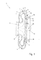
- FIG. 1 The exhaust gas turbocharger 1 consists of an outer housing 2 and an inner housing 3 arranged in the outer housing 2. Both the outer housing 2 and the inner housing 3 are constructed in two shells, the outer housing 2 being based on the image plane a left half shell 4 and a right half shell 5 and the inner housing 3 also consist of a left half shell 6 and a right half shell 7.
- the half shells 4, 5, 6, 7 are each configured in their cross-sections substantially S-shaped. At the respective coupling areas, the half shells 6, 7 of the inner housing and also the half shells 4, 5 of the outer housing are arranged overlapping. In the exemplary embodiment shown here, this overlap 8 is in each case designed in such a way that the respective right half shell 5, 7 overlaps the left half shell 4, 6. Furthermore, the respective half shells 4, 5, 6, 7 are cohesively coupled to one another by a circumferential joining seam 9.
- the inner housing 3 is arranged on the image plane relative to the left side within the outer shell 2 with a sliding seat 10.
- the turbine wheel 11 is located inside the inner housing 3 and is mounted within the exhaust gas turbocharger 1 via a turbine wheel shaft 12 indicated here.
- the turbine wheel shaft 12 thus determines the turbine wheel rotational axis 13.
- the outer housing 2 is coupled to the image plane on the right side with a bearing flange 14.
- the coupling is formed on the one hand in a contact area 15 positively, on the other hand provided with a circumferential joint seam 9.
- an inner edge 16 is formed on the bearing flange 14, The edge 16 thus defines an opening ⁇ within the bearing flange 14.
- the opening ⁇ is penetrated by the collar 17 of the inner housing 3, so that the collar 17 comes to rest on the edge 16.
- the collar 17 has an inner diameter DI and an outer diameter DA which increases in the direction of the bearing flange 14.
- the collar 17 thus engages behind or undercuts the bearing flange 14th in the region of the edge 16, which leads to a fixed positive fixation.
- the position fixation thus produced is additionally reinforced by a circumferential joining seam 18.
- FIG. 2 shows a detailed view of the coupling region between collar 17 and edge 16.
- the edge 16 is shown in the embodiment shown here with a bending radius R, which extends in the direction of the bearing flange 14.
- the bending radius R can be variable as a function and need not be defined by a constant.
- the collar 17 has a contour corresponding to the bending radius R, so that essentially a planar contact is produced here.
- the collar 17 and the edge 16 come in a contact surface 20 substantially flat against the system, wherein the contact surface 20 has a central axis 21 which is oriented substantially in the direction of the turbine wheel rotational axis 13, not shown here.
- the inner housing 3 has a wall thickness W, which is preferably less than 1.5 mm thick. Between the bearing flange 14 and the inner housing 3, a relief gap 22 is provided, which ensures a thermal expansion, stress relief, proper fit of the inner housing 3 on the bearing flange 14 and a high density.
Landscapes
- Engineering & Computer Science (AREA)
- Mechanical Engineering (AREA)
- General Engineering & Computer Science (AREA)
- Chemical & Material Sciences (AREA)
- Chemical Kinetics & Catalysis (AREA)
- General Chemical & Material Sciences (AREA)
- Combustion & Propulsion (AREA)
- Supercharger (AREA)
Abstract
Description
- Die Erfindung betrifft einen Abgasturbolader gemäß den Merkmalen im Oberbegriff von Patentanspruch 1.
- Verbrennungskraftmaschinen, insbesondere im Einsatz für Kraftfahrzeuge, werden in zunehmendem Maße durch Strömungsmaschinen aufgeladen, um den Wirkungsgrad weiter zu steigern und damit den Kraftstoffverbrauch zu senken. Bevorzugt werden als Strömungsmaschinen Turbolader eingesetzt. Dabei werden die Turbolader und insbesondere die Turboladergehäuse sehr genau an die Leistungscharakteristik des jeweiligen Motors angepasst.
- Damit der Turbolader selber mit einem hohen Wirkungsgrad arbeiten kann, ist die Einhaltung exakter Spaltmaße vor, während und nach dem Betrieb von besonderer Bedeutung. Zwischen den einzelnen Betriebszuständen treten Temperaturunterschiede von bis zu mehreren 100°C auf, die bei den verschiedenen Bauteilen und eingesetzten Materialien sowie Materialstärken voneinander abweichende Ausdehnungen der Bauteile untereinander zur Folge haben. Im Falle der Ausdehnung ändern sich auch die Spaltmaße, sodass ein unerwünschtes Blowby innerhalb des Turboladers auftreten kann. Hierdurch reduziert sich der Wirkungsgrad des Turboladers. Ebenfalls kann es dazu kommen, dass die Bauteile durch unterschiedliche Ausdehnungen miteinander in Kontakt kommen. Schlimmstenfalls entstehen Kollisionen der Bauteile untereinander, die Schäden oder aber einen totalen Ausfall des Turboladers mit sich bringen.
- Weiterhin ist die Gewichtsreduzierung aller im Kraftfahrzeugbau eingesetzten Materialien und Komponenten von besonderer Bedeutung. Hierbei steht die Herstellung eines Turboladers, insbesondere eines Turboladergehäuses in Blechbauweise unter dem Aspekt einer Möglichkeit, einen Abgasturbolader besonders gewichtsoptimiert herzustellen.
- In der
DE 100 22 0 52 A1 wird die Entkoppelung von abgasführenden Bauteilen und tragenden bzw. dichtenden Außenstrukturen vorgeschlagen. Während die abgasführenden Bauteile eines Turboladers hohen thermischen Belastungen ausgesetzt sind, sodass sie im Betrieb glühen, sind die thermischen Belastungen der dichtenden Außenstrukturen bedeutend geringer. Allerdings unterliegt auch das Außengehäuse besonders in den Bereichen der Anbindung an das Lagergehäuse eines Turboladers und auch an den Einströmseiten des relativ heißen Abgases sehr hohen thermischen und strömungstechnischen Belastungen. - Das Außengehäuse eines Abgasturboladers besteht in der Regel aus ungeformten Blechschalen, die üblicherweise über thermische Fügeverfahren mit Lagerflanschen verschweißt sind. Ebenfalls mit den Lagerflanschen gekoppelt, ist ein Innengehäuse des Abgasturboladers,
- In der Regel liegen die Innengehäuse an den Lagerflanschen an oder sind zusätzlich mit diesen stoffschlüssig gekoppelt. Hier kann es jedoch im Falle des Anliegens über die verschiedenen thermischen Ausdehnungskoeffizienten zu Undichtigkeiten und somit zu einem Blowby kommen. Im Falle einer stoffschlüssigen Koppelung ist die Wärmeeinflusszone des thermischen Fügevorgangs geometrisch und werkstofftechnisch durch den thermischen Fügevorgang geschwächt. An dieser Stelle kann es unter extremen Belastungen zu Ermüdungsbrüchen oder aber auch Rissbildungen kommen.
- Aufgabe der vorliegenden Erfindung ist es daher, ausgehend vom Stand der Technik, die Dichtigkeit und die Dauerhaltbarkeit eines Abgasturboladers derart zu erhöhen, dass thermische Belastungen nicht zu einem frühen Bauteilversagen führen.
- Die zuvor genannte Aufgabe wird durch einen Abgasturbolader mit den Merkmalen von Patentanspruch 1 gelöst.
- Vorteilhafte Ausführungsformen der vorliegenden Erfindung sind Bestandteil der abhängigen Patentansprüche.
- Der erfindungsgemäße Abgasturbolader, welcher ein Außengehäuse, ein Innengehäuse und ein Turbinenrad aufweist, wobei das Außengehäuse mit einem Lagerflansch stoffschlüssig verbunden ist und das Innengehäuse formschlüssig mit dem Lagerflansch gekoppelt ist, ist dadurch gekennzeichnet, dass ein an dem Innengehäuse ausgebildeter Kragen einer innenliegenden Kante des Lagerflansches in Richtung der Turbinenraddrehachse zumindest abschnittsweise zur Anlage kommt.
- Unter einem Kragen ist im Rahmen der Erfindung eine Ausstellung zu verstehen, die einen kreisrunden Ausschnitt in dem Innengehäuse charakterisiert. Der Kragen weist dabei mit seiner Ausstellung in Richtung der Turbinenraddrehachse. Bei der Koppelung des Innengehäuses mit dem Lagerflansch über den Kragen mit der innenliegenden Kante ist insbesondere zu verstehen, dass der Kragen von einem Innenraum des Innengehäuses wegzeigend ausgebildet ist, sodass er in der Kante des Lagerflansches zur Anlage kommt. Hierdurch ergibt sich insbesondere der Vorteil, dass eine optimale Positionierung des Innengehäuses in radialer und axialer Richtung ermöglicht ist, wodurch wiederum ein Anschleifen bzw. ein Kontakt des Turbinenrades im Betrieb vermieden wird.
- Durch die zumindest abschnittsweise Anlage zwischen Innengehäuse und Lagerflansch über den Kragen und die Kante wird eine formschlüssige Koppelung sichergestellt. Diese formschlüssige Koppelung kompensiert weiter die benötigten Fertigungstoleranzen, die innerhalb des Produktionsprozesses des Abgasturboladers vorhanden sind. Ein Abgasturbolader mit optimaler Spaltbreite kann daher durch eine erfindungsgemäße Koppelung hergestellt werden.
- In einer bevorzugten Ausführungsvariante ist der Kragen zu seinem lagerflanschseitigem Ende hin sich in seinem Durchmesser vergrößernd ausgebildet. Hierunter ist im Rahmen der Erfindung zu verstehen, dass der Kragen in Richtung des mit dem Innengehäuse zu koppelnden Lagerflansches sich in seinem Durchmesser vergrößernd ausgebildet ist. Der Kragen hat so eine aufgetulpte Form. Hierdurch ergeben sich wiederum zum einen strömungstechnische Vorteile, zum anderen wird durch die aufgetulpte bzw. aufgebördelte Formgebung der in dem Kragen auftretende Spannungsverlauf homogenisiert und/oder vermindert.
- Vorzugsweise kommen der Kragen und die Kante formschlüssig zur Anlage, so dass der Kragen die Kante hinterschneidend angeordnet ist. Durch die sich im Durchmesser vergrößernde Ausgestaltung des Lagerflanschseitigen Endes des Kragens ergibt sich ein formschlüssiger Sitz zwischen dem Kragen und der Kante. Der Kragen hintergreift die Kante, sodass eine Rastfunktion oder aber auch Passung ausgebildet ist. Ein besonders fester Sitz zwischen Innengehäuse und Lagerflansch stellt sich somit als erfindungswesentlicher Vorteil ein.
- Bevorzugt weist der Kragen in einem Fußbereich in einem Querschnitt einen Biegeradius auf. Der Kragen ist im Rahmen der Erfindung vorzugsweise als Durchzug ausgebildet. Der Durchzug weist gegenüber dem Innengehäuse, von dem er ausgeht, einen Fußbereich auf, in dem er in einen im Wesentlichen trichterförmigen und/oder zylinderförmigen Kragenabschnitt übergeht. Der Fußbereich weist dabei im Rahmen der Erfindung, besonders bevorzugt im Querschnitt, einen Biegeradius auf, wobei der Biegeradius kein konstanter Radius sein muss, sondern auch ein sich über die Drehbewegung variierender Radius sein kann. Hierdurch ergibt sich gerade im Fußbereich, also im Übergangsbereich vom Innengehäuse zum Kragen ein besonders vorteiliger Spannungsverlauf des hergestellten Abgasturboladers,
- Weiterhin bevorzugt weist die Kante im Querschnitt eine dem Biegeradius korrespondierende Geometrie auf. Die Kante und der Kragen liegen somit zumindest abschnittsweise aneinander, sodass hier wiederum eine besonders vorteilige formschlüssige Koppelung sichergestellt ist. Dies bietet insbesondere Vorteile bei der Positionierung des Innensystems in radialer und axialer Richtung, sowie der Maßhaltigkeit des Innengehäuses während des Betriebes des Abgasturboladers.
- In einer besonders bevorzugten Ausführungsvariante der vorliegenden Erfindung sind die Kante und der Kragen zumindest abschnittsweise im Biegeradius flächig zur Anlage kommend angeordnet. Dieses wirkt sich insbesondere vorteilig auf den Betrieb des Abgasturboladers aus. Die auftretenden Bauteilausdehnungen und die daraus resultierenden Spannungen werden somit innerhalb des Innengehäuses derart homogenisiert, das während des gesamten Betriebes ein fester und dichter Sitz zwischen Innengehäuse und Lagerflansch gegeben ist, ohne dass kritische Spannungsspitzen entstehen.
- In einer weiteren bevorzugten Ausführungsvariante kommen die Kante und der Kragen in Richtung der Turbinenraddrehachse auf einem Abschnitt flächig zur Anlage, wobei die Anlagefläche in Richtung der Turbinenraddrehachse orientiert ist. Hierdurch ergibt sich eine Länge, in der der Kragen des Innengehäuses flächig mit der Kante des Lagerflansches zur Anlage kommt. Die mittlere Orientierungsachse der Anlagefläche verläuft dabei im Wesentlichen in Richtung der Turbinenraddrehachse orientiert. Hierdurch ergibt sich der Vorteil, dass elastische Reserven des Innengehäuses und des Kragens vorhanden sind. Spannungen, die aufgrund verschiedener thermischer Ausdehnungen der Bauteile auftreten, können sich insbesondere in der Anlagefläche in Richtung der Turbinenraddrehachse verteilen und damit zu einer höheren Dauerhaltbarkeit des erfindungsgemäßen Abgasturboladers führen.
- Weiterhin ist das Innengehäuse zweischalig ausgebildet, wobei eine lagerflanschseitige Halbschale in ihrem Querschnitt S-förmig konfiguriert ist. Im Rahmen der Erfindung ist der Kragen bereits Bestandteil eines Endabschnitts der S-förmigen Konfiguration. Dies wirkt sich insbesondere auf die kostengünstige Herstellungsmöglichkeit der Halbschale aus. Durch die S-förmige Konfiguration ist die Halbschale mittels nur eines Arbeitsvorgangs in einem Umformwerkzeug herstellbar. Ein weiterer sich ergebender Vorteil ist, dass wiederum die im Innengehäuse auftretenden Spannungen und auch die zwischen dem Innengehäuse und Außengehäuse auftretenden Spannungen durch die S-förmige Konfiguration federartig ausgeglichen werden. Das Innengehäuse hat dadurch die Möglichkeiten, sich relativ zum Außengehäuse und absolut zu sich selber auszudehnen, ohne sich dabei negativ auf den Wirkungsgrad bzw. das Betriebsverhalten des Abgasturboladers auszuwirken.
- In einer weiteren bevorzugten Ausführungsvariante der vorliegenden Erfindung weist das Innengehäuse eine Wandstärke von weniger als 1,5 mm, bevorzugt weniger als 1 mm auf. Durch die erfindungsgemäße Koppelung des Innengehäuses mit dem Lagerflansch ist es möglich, das Innengehäuse mit einer besonders geringen Wandstärke herzustellen. In der Folge treten weniger Eigenspannung innerhalb des Innengehäuses auf und auch gerade beim Motorstartverhalten ergibt sich nur ein geringer Wärmeeintrag in das Innengehäuse, gegenüber einer hohen Wandstärke. In der Folge kommt der Abgasturbolader schneller auf Betriebstemperatur und somit in einen optimalen Wirkungsgradbereich. Weiterhin kommt das Gesamtsystem der Verbrennungskraftmaschine und auch der Abgasnachbehandlung ebenfalls schneller auf Betriebstemperatur, sodass gerade beispielsweise im Katalysatoranspringverhalten eine deutliche Reduzierung der Emissionswerte während des Startvorgangs realisiert werden kann.
- In einer weiteren bevorzugten Ausführungsvariante sind der Kragen und die Kante stoffschlüssig miteinander gekoppelt, vorzugsweise über eine radiale umlaufende Fügenaht. Zur weiteren Verstärkung der Koppelung zwischen Innengehäuse und Lagerflansch wird zusätzlich zu der formschlüssigen Verbindung eine stoffschlüssige Verbindung hergestellt. Dies wirkt sich wiederum positiv auf die Dauerhaltbarkeit der Verbindung, sowie auf die Dichtigkeit der Verbindung aus.
- In einer besonders bevorzugten Ausführungsvariante hintergreift der Kragen die Kante und in einem Fügeabschnitt am Lagerflansch seitigem Ende des Kragens ist der Kragen mit der Kante umlaufend mittels thermischem Fügen gekoppelt. Hierdurch ist sichergestellt, dass die Fügenaht nicht der direkten Strömung des heißen Abgases ausgesetzt ist. Eine Bauteilschwächung in diesem Bereich, hervorgerufen durch die Wärmeeinflusszone des thermischen Fügeprozesses sowie die Fügenaht selber sind folglich nicht der direkten Strömung des heißen und hoch korrosiven Abgases ausgesetzt. Dies wirkt sich wiederum besonders vorteilig auf die Dauerhaltbarkeit des erfindungsgemäßen Abgasturboladers aus.
- Weitere Vorteile, Merkmale, Aspekte und Eigenschaften der vorliegenden Erfindung ergeben sich aus der folgenden Beschreibung, bevorzugte Ausführungsformen anhand der schematischen Zeichnungen. Diese dienen dem einfachen Verständnis der Erfindung. Es zeigen:
- Figur 1
- einen erfindungsgemäßen Abgasturbolader in einer Schnittansicht und
- Figur 2
- eine Detailschnittansicht der Koppelung zwischen Lagerflansch und Innengehäuse.
- In den Figuren werden für gleiche oder ähnliche Bauteile die gleichen Bezugszeichen verwendet, auch wenn eine wiederholte Beschreibung aus Vereinfachungsgründen entfällt.
-
Figur 1 zeigt eine schnitttechnische Darstellung eines erfindungsgemäßen Abgasturboladers 1. Der Abgasturbolader 1 besteht dabei aus einem Außengehäuse 2 und einem in dem Außengehäuse 2 angeordneten Innengehäuse 3. Sowohl das Außengehäuse 2 als auch das Innengehäuse 3 sind zweischalig aufgebaut, wobei auf die Bildebene bezogen das Außengehäuse 2 aus einer linken Halbschale 4 und einer rechten Halbschale 5 und das Innengehäuse 3 ebenfalls aus einer linken Halbschale 6 und einer rechten Halbschale 7 bestehen. - Die Halbschalen 4, 5, 6, 7 sind in ihren Querschnitten jeweils im Wesentlichen S-förmig konfiguriert. An den jeweiligen Koppelungsbereichen sind die Halbschalen 6, 7 des Innengehäuses und auch die Halbschalen 4, 5 des Außengehäuses überlappend angeordnet. Diese Überlappung 8 ist im hier gezeigten Ausführungsbeispiel jeweils so ausgebildet, dass die jeweils rechte Halbschale 5, 7 die linke Halbschale 4, 6 überlappt Weiterhin sind die jeweiligen Halbschalen 4, 5, 6, 7, mit einer umlaufenden Fügenaht 9 miteinander stoffschlüssig gekoppelt. Das Innengehäuse 3 ist auf der auf die Bildebene bezogenen linken Seite innerhalb der Außenschale 2 mit einem Schiebesitz 10 angeordnet.
- Das Turbinenrad 11 befindet sich innerhalb des Innengehäuses 3 und ist über eine hier angedeutete Turbinenradwelle 12 innerhalb des Abgasturboladers 1 gelagert. Die Turbinenradwelle 12 bestimmt somit die Turbinenraddrehachse 13. Das Außengehäuse 2 ist auf die Bildebene bezogen auf der rechten Seite mit einem Lagerflansch 14 gekoppelt. Die Koppelung ist zum einen in einem Anlagebereich 15 formschlüssig ausgebildet, zum anderen mit einer umlaufenden Fügenaht 9 versehen. Weiterhin ist an dem Lagerflansch 14 eine innenliegende Kante 16 ausgebildet, Die Kante 16 definiert somit eine Öffnung Ö innerhalb des Lagerflansches 14. Die Öffnung Ö wird durch den Kragen 17 des Innengehäuses 3 durchgriffen, sodass der Kragen 17 an der Kante 16 zur Anlage kommt. Der Kragen 17 weist dazu einen Innendurchmesser DI auf und einen sich in Richtung des Lagerflansch 14 vergrößernden Außendurchmesser DA. Der Kragen 17 hintergreift bzw. hinterschneidet somit den Lagerflansch 14 im Bereich der Kante 16, was zu einer festen formschlüssigen Fixierung führt. Weiterhin ist die so hergestellte Lagefixierung durch eine umlaufende Fügenaht 18 zusätzlich verstärkt.
-
Figur 2 zeigt eine Detailansicht des Koppelungsbereichs zwischen Kragen 17 und Kante 16. Die Kante 16 ist in der hier gezeigten Ausführungsvariante mit einem Biegeradius R dargestellt, der sich in Richtung des Lagerflansches 14 erstreckt. Der Biegeradius R kann dabei als Funktion veränderbar sein und muss nicht durch eine Konstante definiert sein. Der Kragen 17 weist in einem Fußbereich 19 eine dem Biegeradius R korrespondierende Kontur auf, sodass hier im Wesentlichen eine flächige Anlage hergestellt ist. - Weiterhin kommen der Kragen 17 und die Kante 16 in einer Anlagefläche 20 im Wesentlichen flächig zur Anlage, wobei die Anlagefläche 20 eine Mittelachse 21 aufweist, die im Wesentlichen in Richtung der hier nicht gezeigten Turbinenraddrehachse 13 orientiert ist. Weiterhin weist das Innengehäuse 3 eine Wandstärke W auf, die vorzugsweise weniger als 1,5 mm dick ist. Zwischen dem Lagerflansch 14 und dem Innengehäuse 3 ist ein Entlastungsspalt 22 vorgesehen, der bei thermischen Ausdehnungen ein Spannungsabbau, einen einwandfreien Sitz des Innengehäuses 3 am Lagerflansch 14 und eine hohe Dichtigkeit sicherstellt.
-
- 1 -
- Abgasturbolader
- 2-
- Außengehäuse
- 3 -
- Innegehäuse
- 4 -
- linke Halbschale zu 2.
- 5 -
- rechte Halbschale zu 2,
- 6 -
- linke Halbschale zu 3.
- 7 -
- rechte Halbschale zu 3.
- 8-
- Überlappung
- 9-
- Fügenaht zu 2, 3, 15
- 10-
- Schiebesitz
- 11 -
- Turbinenrad
- 12-
- Turbinenradwelle
- 13-
- Turbinenraddrehachse
- 14-
- Lagerflansch
- 15-
- Anlagebereich
- 16-
- Kante
- 17-
- Kragen
- 18-
- Fügenaht zu 17.
- 19-
- Fußbereich zu 17.
- 20-
- Anlagefläche
- 21 -
- Mittelachse zu 20.
- 22-
- Entlastungsspalt
- W-
- Wandstärke
- DI-
- Innendurchmesser
- DA -
- Außendurchmesser
- Ö-
- Öffnung
- R-
- Biegeradius
Claims (11)
- Abgasturbolader (1), welcher ein Außengehäuse (2), ein Innengehäuse (3) und ein Turbinenrad (11) aufweist, wobei das Außengehäuse (2) mit einem Lagerflansch (14) stoffschlüssig verbunden ist und das Innengehäuse (3) formschlüssig mit dem Lagerflansch (14) gekoppelt ist, dadurch gekennzeichnet, dass ein an dem Innengehäuse (3) ausgebildeter Kragen (17) an einer innenliegenden Kante (16) des Lagerflansches (14) in Richtung der Turbinenraddrehachse (13) zumindest abschnittsweise zur Anlage kommt.
- Abgasturbolader nach Anspruch 1, dadurch gekennzeichnet, dass der Kragen (17) zu seinem lagerflanschseitigen Ende hin sich in seinem Durchmesser vergrößernd ausgebildet ist.
- Abgasturbolader nach Anspruch 1 oder 2, dadurch gekennzeichnet, dass der Kragen (17) und die Kante (16) formschlüssig zur Anlage kommen, so dass der Kragen (17) die Kante (16) hinterschneidend angeordnet ist.
- Abgasturbolader nach einem der Ansprüche 1 bis 3, dadurch gekennzeichnet, dass der Kragen (17) in einem Fußbereich (19) im Querschnitt einen Biegeradius (R) aufweist.
- Abgasturbolader nach Anspruch 4, dadurch gekennzeichnet, dass die Kante (16) im Querschnitt eine dem Biegeradius (R) korrespondierende Geometrie aufweist.
- Abgasturbolader nach Anspruch 5, dadurch gekennzeichnet, dass die Kante (16) und der Kragen (17) zumindest abschnittsweise im Biegeradius (R) flächig zur Anlage kommend angeordnet sind.
- Abgasturbolader nach einem der Ansprüche 1 bis 6, dadurch gekennzeichnet, dass die Kante (16) und der Kragen (17) in Richtung der Turbinenraddrehachse (13) auf einem Abschnitt flächig zur Anlage kommen, wobei die Anlagefläche (20) in Richtung der Turbinenraddrehachse (13) orientiert ist.
- Abgasturbolader nach einem der Ansprüche 1 bis 7, dadurch gekennzeichnet, dass das Innengehäuse (3) zweischalig ausgebildet ist, wobei eine lagerflanschseitige Halbschale in Ihrem Querschnitt S-förmig konfiguriert ist.
- Abgasturbolader nach einem der Ansprüche 1 bis 8, dadurch gekennzeichnet, dass das Innengehäuse (3) eine Wandstärke (W) von weniger als 1,5 mm, bevorzugt weniger als 1 mm aufweist.
- Abgasturbolader nach einem der Ansprüche 1 bis 9, dadurch gekennzeichnet, dass der Kragen (17) und die Kante (16) stoffschlüssig miteinander gekoppelt sind, vorzugsweise über eine radial umlaufende Fügenaht (18).
- Abgasturbolader nach einem der Ansprüche 1 bis 10, dadurch gekennzeichnet, dass der Kragen (17) die Kante (16) hinterschneidet und in einem Fügeabschnitt am lagerflanschseitigen Ende des Kragens (17) umlaufend mittels thermischem Fügen mit diesem gekoppelt ist.
Applications Claiming Priority (1)
| Application Number | Priority Date | Filing Date | Title |
|---|---|---|---|
| DE102010021114A DE102010021114A1 (de) | 2010-05-20 | 2010-05-20 | Abgasturbolader |
Publications (3)
| Publication Number | Publication Date |
|---|---|
| EP2388455A2 true EP2388455A2 (de) | 2011-11-23 |
| EP2388455A3 EP2388455A3 (de) | 2013-10-23 |
| EP2388455B1 EP2388455B1 (de) | 2017-04-05 |
Family
ID=43629590
Family Applications (1)
| Application Number | Title | Priority Date | Filing Date |
|---|---|---|---|
| EP11154785.7A Not-in-force EP2388455B1 (de) | 2010-05-20 | 2011-02-17 | Abgasturbolader |
Country Status (4)
| Country | Link |
|---|---|
| US (1) | US20110286837A1 (de) |
| EP (1) | EP2388455B1 (de) |
| JP (1) | JP2011241835A (de) |
| DE (1) | DE102010021114A1 (de) |
Cited By (3)
| Publication number | Priority date | Publication date | Assignee | Title |
|---|---|---|---|---|
| EP3045687A1 (de) * | 2015-01-14 | 2016-07-20 | Benteler Automobiltechnik GmbH | Turbinengehäuse für einen abgasturbolader |
| CN108506055A (zh) * | 2017-02-27 | 2018-09-07 | 曼柴油机和涡轮机欧洲股份公司 | 涡轮增压器 |
| US10288279B2 (en) | 2013-09-19 | 2019-05-14 | Alstom Technology Ltd | Flue gas heat recovery integration |
Families Citing this family (23)
| Publication number | Priority date | Publication date | Assignee | Title |
|---|---|---|---|---|
| DE102009053101B4 (de) * | 2009-11-13 | 2016-02-25 | Continental Automotive Gmbh | Turbolader mit einem Turboladergehäuse und einer Aufnahmeeinrichtung für das Laufzeug des Turboladers |
| DE102011050506B4 (de) * | 2011-05-19 | 2013-04-18 | Benteler Automobiltechnik Gmbh | Abgasturbolader |
| JP5910114B2 (ja) * | 2012-01-27 | 2016-04-27 | トヨタ自動車株式会社 | タービンハウジング及び排気タービン過給機 |
| DE102012009090A1 (de) * | 2012-05-09 | 2013-11-14 | Benteler Automobiltechnik Gmbh | Anbindung eines doppelwandigen Turboladergehäuses |
| GB2530699B (en) * | 2013-06-28 | 2016-09-21 | Borgwarner Inc | Turbocharger compressor-end carbon face seal |
| DE102013109446B4 (de) | 2013-08-30 | 2015-11-26 | Benteler Automobiltechnik Gmbh | Abgaskrümmer mit Isolationshülse |
| DE102013111561A1 (de) * | 2013-10-21 | 2015-04-23 | Ihi Charging Systems International Gmbh | Abgasturbolader |
| CN108757063B (zh) * | 2013-12-27 | 2021-04-02 | 三菱重工发动机和增压器株式会社 | 涡轮壳体 |
| DE112015000287T5 (de) * | 2014-02-04 | 2016-11-17 | Borgwarner Inc. | Abgasturbolader |
| DE102014103809A1 (de) | 2014-03-20 | 2015-12-03 | Benteler Automobiltechnik Gmbh | Abgaskrümmer für eine Abgasanlage eines Verbrennungsmotors |
| DE102014103820A1 (de) | 2014-03-20 | 2015-09-24 | Benteler Automobiltechnik Gmbh | Abgaskrümmer für eine Abgasanlage eines Verbrennungsmotors |
| DE102014105656B4 (de) | 2014-04-22 | 2017-02-02 | Benteler Automobiltechnik Gmbh | Abgaskrümmer |
| DE102014116445B4 (de) | 2014-11-11 | 2016-08-11 | Benteler Automobiltechnik Gmbh | Turbinengehäuse für einen Abgasturbolader |
| JP2016156279A (ja) * | 2015-02-23 | 2016-09-01 | カルソニックカンセイ株式会社 | タービンハウジング |
| JP6204398B2 (ja) * | 2015-03-23 | 2017-09-27 | カルソニックカンセイ株式会社 | タービンハウジング |
| US10519806B2 (en) * | 2015-11-06 | 2019-12-31 | Calsonic Kansei Corporation | Turbine housing |
| US10472988B2 (en) | 2017-01-30 | 2019-11-12 | Garrett Transportation I Inc. | Sheet metal turbine housing and related turbocharger systems |
| US10494955B2 (en) * | 2017-01-30 | 2019-12-03 | Garrett Transportation I Inc. | Sheet metal turbine housing with containment dampers |
| US10436069B2 (en) * | 2017-01-30 | 2019-10-08 | Garrett Transportation I Inc. | Sheet metal turbine housing with biaxial volute configuration |
| US10544703B2 (en) | 2017-01-30 | 2020-01-28 | Garrett Transportation I Inc. | Sheet metal turbine housing with cast core |
| DE102018107304A1 (de) * | 2018-03-27 | 2019-10-02 | Man Energy Solutions Se | Turbolader |
| DE102018127708A1 (de) * | 2018-11-07 | 2020-05-07 | Man Energy Solutions Se | Verfahren zum Bearbeiten eines Gehäuses eines Turboladers |
| US11732729B2 (en) | 2021-01-26 | 2023-08-22 | Garrett Transportation I Inc | Sheet metal turbine housing |
Citations (1)
| Publication number | Priority date | Publication date | Assignee | Title |
|---|---|---|---|---|
| DE10022052A1 (de) | 1999-05-26 | 2001-03-01 | Gillet Heinrich Gmbh | Turbinengehäuse für Abgasturbolader |
Family Cites Families (8)
| Publication number | Priority date | Publication date | Assignee | Title |
|---|---|---|---|---|
| US7074009B2 (en) * | 2000-06-07 | 2006-07-11 | Borgwarner, Inc. | Casing assembly for the turbine of an exhaust turbochanger |
| DE10028160C2 (de) * | 2000-06-07 | 2003-03-27 | Borgwarner Inc | Gehäusegruppe für die Turbine eines Abgas-Turboladers |
| JP2002054447A (ja) * | 2000-08-09 | 2002-02-20 | Aisin Takaoka Ltd | タービンハウジング |
| JP2003293779A (ja) * | 2002-03-29 | 2003-10-15 | Toyota Motor Corp | タービンハウジング |
| DE10218436C1 (de) * | 2002-04-25 | 2003-08-14 | Benteler Automobiltechnik Gmbh | Abgasturbine für einen Turbolader |
| JP2006161573A (ja) * | 2004-12-02 | 2006-06-22 | Toyota Motor Corp | ターボチャージャのタービンハウジング |
| JP4448064B2 (ja) * | 2005-06-24 | 2010-04-07 | トヨタ自動車株式会社 | タービンハウジング |
| DE102008052552B4 (de) * | 2008-10-21 | 2015-06-11 | Benteler Automobiltechnik Gmbh | Turbinengehäuse und Verfahren zu seiner Herstellung |
-
2010
- 2010-05-20 DE DE102010021114A patent/DE102010021114A1/de not_active Ceased
-
2011
- 2011-02-17 EP EP11154785.7A patent/EP2388455B1/de not_active Not-in-force
- 2011-05-18 US US13/110,421 patent/US20110286837A1/en not_active Abandoned
- 2011-05-19 JP JP2011112261A patent/JP2011241835A/ja active Pending
Patent Citations (1)
| Publication number | Priority date | Publication date | Assignee | Title |
|---|---|---|---|---|
| DE10022052A1 (de) | 1999-05-26 | 2001-03-01 | Gillet Heinrich Gmbh | Turbinengehäuse für Abgasturbolader |
Cited By (4)
| Publication number | Priority date | Publication date | Assignee | Title |
|---|---|---|---|---|
| US10288279B2 (en) | 2013-09-19 | 2019-05-14 | Alstom Technology Ltd | Flue gas heat recovery integration |
| EP3045687A1 (de) * | 2015-01-14 | 2016-07-20 | Benteler Automobiltechnik GmbH | Turbinengehäuse für einen abgasturbolader |
| US10094243B2 (en) | 2015-01-14 | 2018-10-09 | Benteler Automobiltechnik Gmbh | Turbine housing for an exhaust turbocharger |
| CN108506055A (zh) * | 2017-02-27 | 2018-09-07 | 曼柴油机和涡轮机欧洲股份公司 | 涡轮增压器 |
Also Published As
| Publication number | Publication date |
|---|---|
| EP2388455B1 (de) | 2017-04-05 |
| EP2388455A3 (de) | 2013-10-23 |
| US20110286837A1 (en) | 2011-11-24 |
| JP2011241835A (ja) | 2011-12-01 |
| DE102010021114A1 (de) | 2011-11-24 |
Similar Documents
| Publication | Publication Date | Title |
|---|---|---|
| EP2388455B1 (de) | Abgasturbolader | |
| EP2572092B1 (de) | Tubinengehäuse eines abgasturboladers | |
| EP2180163B1 (de) | Turbinengehäuse und Verfahren zu seiner Herstellung | |
| EP2525050B1 (de) | Abgasturbolader | |
| EP2354490B1 (de) | Abgasbaugruppe | |
| WO2010081697A1 (de) | Verbindungsanordnung eines turbinengehäuses mit einem lagergehäuse und abgasturbolader | |
| EP2728122A1 (de) | Dichtungsträgerfixierung für eine Strömungsmaschine | |
| DE102012209562B4 (de) | Turbinengehäuse für einen Abgasturbolader | |
| DE102008020732A1 (de) | Ladeeinrichtung | |
| DE112020001965B4 (de) | Turbinengehäuse und Turbolader | |
| DE112019006906B4 (de) | Düsenvorrichtung und abgasturbolader | |
| WO2012035163A1 (de) | Abgasbehandlungseinheit für eine abgasrückführleitung | |
| EP1939407B1 (de) | Turbolader | |
| DE102014106415A1 (de) | Verdichtergehäuse | |
| EP2867534B1 (de) | Abgasturbolader | |
| DE102011086089A1 (de) | Ladeeinrichtung | |
| DE102014102038B4 (de) | Abgasanlagen-Komponente und Verfahren zum Verbinden eines ersten Rohrbauteils und eines zweiten Rohrbauteils einer Abgasanlagen-Komponente | |
| EP3215739B1 (de) | Pumpeneinheit für reduktionsmittel einer abgasreinigungsanlage | |
| DE102019123191A1 (de) | Regelstange für eine aufladevorrichtung | |
| EP3026317B1 (de) | Verbindungsstück für fluidführende Rohre | |
| DE102016012658A1 (de) | Rotor für eine Strömungsmaschine, insbesondere eines Kraftfahrzeugs | |
| DE102013018005A1 (de) | Wellen-Naben-Verbindung | |
| DE102012209560A1 (de) | Turbinengehäuse für einen Abgasturbolader | |
| DE102008060850A1 (de) | Variable Turbinengeometrie, Schaufellagerscheibe und Ladeeinrichtung |
Legal Events
| Date | Code | Title | Description |
|---|---|---|---|
| AK | Designated contracting states |
Kind code of ref document: A2 Designated state(s): AL AT BE BG CH CY CZ DE DK EE ES FI FR GB GR HR HU IE IS IT LI LT LU LV MC MK MT NL NO PL PT RO RS SE SI SK SM TR |
|
| AX | Request for extension of the european patent |
Extension state: BA ME |
|
| PUAI | Public reference made under article 153(3) epc to a published international application that has entered the european phase |
Free format text: ORIGINAL CODE: 0009012 |
|
| PUAL | Search report despatched |
Free format text: ORIGINAL CODE: 0009013 |
|
| AK | Designated contracting states |
Kind code of ref document: A3 Designated state(s): AL AT BE BG CH CY CZ DE DK EE ES FI FR GB GR HR HU IE IS IT LI LT LU LV MC MK MT NL NO PL PT RO RS SE SI SK SM TR |
|
| AX | Request for extension of the european patent |
Extension state: BA ME |
|
| RIC1 | Information provided on ipc code assigned before grant |
Ipc: F02C 6/12 20060101AFI20130918BHEP Ipc: F01D 25/24 20060101ALI20130918BHEP |
|
| 17P | Request for examination filed |
Effective date: 20140220 |
|
| GRAP | Despatch of communication of intention to grant a patent |
Free format text: ORIGINAL CODE: EPIDOSNIGR1 |
|
| INTG | Intention to grant announced |
Effective date: 20161020 |
|
| GRAS | Grant fee paid |
Free format text: ORIGINAL CODE: EPIDOSNIGR3 |
|
| GRAA | (expected) grant |
Free format text: ORIGINAL CODE: 0009210 |
|
| AK | Designated contracting states |
Kind code of ref document: B1 Designated state(s): AL AT BE BG CH CY CZ DE DK EE ES FI FR GB GR HR HU IE IS IT LI LT LU LV MC MK MT NL NO PL PT RO RS SE SI SK SM TR |
|
| REG | Reference to a national code |
Ref country code: GB Ref legal event code: FG4D Free format text: NOT ENGLISH |
|
| REG | Reference to a national code |
Ref country code: CH Ref legal event code: EP |
|
| REG | Reference to a national code |
Ref country code: AT Ref legal event code: REF Ref document number: 882076 Country of ref document: AT Kind code of ref document: T Effective date: 20170415 |
|
| REG | Reference to a national code |
Ref country code: IE Ref legal event code: FG4D Free format text: LANGUAGE OF EP DOCUMENT: GERMAN |
|
| REG | Reference to a national code |
Ref country code: DE Ref legal event code: R096 Ref document number: 502011011962 Country of ref document: DE |
|
| REG | Reference to a national code |
Ref country code: NL Ref legal event code: MP Effective date: 20170405 |
|
| REG | Reference to a national code |
Ref country code: LT Ref legal event code: MG4D |
|
| PG25 | Lapsed in a contracting state [announced via postgrant information from national office to epo] |
Ref country code: NL Free format text: LAPSE BECAUSE OF FAILURE TO SUBMIT A TRANSLATION OF THE DESCRIPTION OR TO PAY THE FEE WITHIN THE PRESCRIBED TIME-LIMIT Effective date: 20170405 |
|
| PG25 | Lapsed in a contracting state [announced via postgrant information from national office to epo] |
Ref country code: HR Free format text: LAPSE BECAUSE OF FAILURE TO SUBMIT A TRANSLATION OF THE DESCRIPTION OR TO PAY THE FEE WITHIN THE PRESCRIBED TIME-LIMIT Effective date: 20170405 Ref country code: FI Free format text: LAPSE BECAUSE OF FAILURE TO SUBMIT A TRANSLATION OF THE DESCRIPTION OR TO PAY THE FEE WITHIN THE PRESCRIBED TIME-LIMIT Effective date: 20170405 Ref country code: GR Free format text: LAPSE BECAUSE OF FAILURE TO SUBMIT A TRANSLATION OF THE DESCRIPTION OR TO PAY THE FEE WITHIN THE PRESCRIBED TIME-LIMIT Effective date: 20170706 Ref country code: NO Free format text: LAPSE BECAUSE OF FAILURE TO SUBMIT A TRANSLATION OF THE DESCRIPTION OR TO PAY THE FEE WITHIN THE PRESCRIBED TIME-LIMIT Effective date: 20170705 Ref country code: LT Free format text: LAPSE BECAUSE OF FAILURE TO SUBMIT A TRANSLATION OF THE DESCRIPTION OR TO PAY THE FEE WITHIN THE PRESCRIBED TIME-LIMIT Effective date: 20170405 Ref country code: ES Free format text: LAPSE BECAUSE OF FAILURE TO SUBMIT A TRANSLATION OF THE DESCRIPTION OR TO PAY THE FEE WITHIN THE PRESCRIBED TIME-LIMIT Effective date: 20170405 |
|
| PG25 | Lapsed in a contracting state [announced via postgrant information from national office to epo] |
Ref country code: LV Free format text: LAPSE BECAUSE OF FAILURE TO SUBMIT A TRANSLATION OF THE DESCRIPTION OR TO PAY THE FEE WITHIN THE PRESCRIBED TIME-LIMIT Effective date: 20170405 Ref country code: IS Free format text: LAPSE BECAUSE OF FAILURE TO SUBMIT A TRANSLATION OF THE DESCRIPTION OR TO PAY THE FEE WITHIN THE PRESCRIBED TIME-LIMIT Effective date: 20170805 Ref country code: BG Free format text: LAPSE BECAUSE OF FAILURE TO SUBMIT A TRANSLATION OF THE DESCRIPTION OR TO PAY THE FEE WITHIN THE PRESCRIBED TIME-LIMIT Effective date: 20170705 Ref country code: PL Free format text: LAPSE BECAUSE OF FAILURE TO SUBMIT A TRANSLATION OF THE DESCRIPTION OR TO PAY THE FEE WITHIN THE PRESCRIBED TIME-LIMIT Effective date: 20170405 Ref country code: SE Free format text: LAPSE BECAUSE OF FAILURE TO SUBMIT A TRANSLATION OF THE DESCRIPTION OR TO PAY THE FEE WITHIN THE PRESCRIBED TIME-LIMIT Effective date: 20170405 Ref country code: RS Free format text: LAPSE BECAUSE OF FAILURE TO SUBMIT A TRANSLATION OF THE DESCRIPTION OR TO PAY THE FEE WITHIN THE PRESCRIBED TIME-LIMIT Effective date: 20170405 |
|
| REG | Reference to a national code |
Ref country code: DE Ref legal event code: R097 Ref document number: 502011011962 Country of ref document: DE |
|
| PG25 | Lapsed in a contracting state [announced via postgrant information from national office to epo] |
Ref country code: RO Free format text: LAPSE BECAUSE OF FAILURE TO SUBMIT A TRANSLATION OF THE DESCRIPTION OR TO PAY THE FEE WITHIN THE PRESCRIBED TIME-LIMIT Effective date: 20170405 Ref country code: CZ Free format text: LAPSE BECAUSE OF FAILURE TO SUBMIT A TRANSLATION OF THE DESCRIPTION OR TO PAY THE FEE WITHIN THE PRESCRIBED TIME-LIMIT Effective date: 20170405 Ref country code: DK Free format text: LAPSE BECAUSE OF FAILURE TO SUBMIT A TRANSLATION OF THE DESCRIPTION OR TO PAY THE FEE WITHIN THE PRESCRIBED TIME-LIMIT Effective date: 20170405 Ref country code: EE Free format text: LAPSE BECAUSE OF FAILURE TO SUBMIT A TRANSLATION OF THE DESCRIPTION OR TO PAY THE FEE WITHIN THE PRESCRIBED TIME-LIMIT Effective date: 20170405 Ref country code: SK Free format text: LAPSE BECAUSE OF FAILURE TO SUBMIT A TRANSLATION OF THE DESCRIPTION OR TO PAY THE FEE WITHIN THE PRESCRIBED TIME-LIMIT Effective date: 20170405 |
|
| PLBE | No opposition filed within time limit |
Free format text: ORIGINAL CODE: 0009261 |
|
| STAA | Information on the status of an ep patent application or granted ep patent |
Free format text: STATUS: NO OPPOSITION FILED WITHIN TIME LIMIT |
|
| PG25 | Lapsed in a contracting state [announced via postgrant information from national office to epo] |
Ref country code: SM Free format text: LAPSE BECAUSE OF FAILURE TO SUBMIT A TRANSLATION OF THE DESCRIPTION OR TO PAY THE FEE WITHIN THE PRESCRIBED TIME-LIMIT Effective date: 20170405 Ref country code: IT Free format text: LAPSE BECAUSE OF FAILURE TO SUBMIT A TRANSLATION OF THE DESCRIPTION OR TO PAY THE FEE WITHIN THE PRESCRIBED TIME-LIMIT Effective date: 20170405 |
|
| 26N | No opposition filed |
Effective date: 20180108 |
|
| PG25 | Lapsed in a contracting state [announced via postgrant information from national office to epo] |
Ref country code: SI Free format text: LAPSE BECAUSE OF FAILURE TO SUBMIT A TRANSLATION OF THE DESCRIPTION OR TO PAY THE FEE WITHIN THE PRESCRIBED TIME-LIMIT Effective date: 20170405 |
|
| REG | Reference to a national code |
Ref country code: CH Ref legal event code: PL |
|
| PG25 | Lapsed in a contracting state [announced via postgrant information from national office to epo] |
Ref country code: MC Free format text: LAPSE BECAUSE OF FAILURE TO SUBMIT A TRANSLATION OF THE DESCRIPTION OR TO PAY THE FEE WITHIN THE PRESCRIBED TIME-LIMIT Effective date: 20170405 Ref country code: MT Free format text: LAPSE BECAUSE OF FAILURE TO SUBMIT A TRANSLATION OF THE DESCRIPTION OR TO PAY THE FEE WITHIN THE PRESCRIBED TIME-LIMIT Effective date: 20170405 |
|
| GBPC | Gb: european patent ceased through non-payment of renewal fee |
Effective date: 20180217 |
|
| REG | Reference to a national code |
Ref country code: IE Ref legal event code: MM4A |
|
| REG | Reference to a national code |
Ref country code: BE Ref legal event code: MM Effective date: 20180228 |
|
| PG25 | Lapsed in a contracting state [announced via postgrant information from national office to epo] |
Ref country code: CH Free format text: LAPSE BECAUSE OF NON-PAYMENT OF DUE FEES Effective date: 20180228 Ref country code: LI Free format text: LAPSE BECAUSE OF NON-PAYMENT OF DUE FEES Effective date: 20180228 Ref country code: LU Free format text: LAPSE BECAUSE OF NON-PAYMENT OF DUE FEES Effective date: 20180217 |
|
| REG | Reference to a national code |
Ref country code: FR Ref legal event code: ST Effective date: 20181031 |
|
| PG25 | Lapsed in a contracting state [announced via postgrant information from national office to epo] |
Ref country code: IE Free format text: LAPSE BECAUSE OF NON-PAYMENT OF DUE FEES Effective date: 20180217 |
|
| PG25 | Lapsed in a contracting state [announced via postgrant information from national office to epo] |
Ref country code: FR Free format text: LAPSE BECAUSE OF NON-PAYMENT OF DUE FEES Effective date: 20180228 Ref country code: GB Free format text: LAPSE BECAUSE OF NON-PAYMENT OF DUE FEES Effective date: 20180217 Ref country code: BE Free format text: LAPSE BECAUSE OF NON-PAYMENT OF DUE FEES Effective date: 20180228 |
|
| REG | Reference to a national code |
Ref country code: AT Ref legal event code: MM01 Ref document number: 882076 Country of ref document: AT Kind code of ref document: T Effective date: 20180217 |
|
| PG25 | Lapsed in a contracting state [announced via postgrant information from national office to epo] |
Ref country code: AT Free format text: LAPSE BECAUSE OF NON-PAYMENT OF DUE FEES Effective date: 20180217 |
|
| PG25 | Lapsed in a contracting state [announced via postgrant information from national office to epo] |
Ref country code: TR Free format text: LAPSE BECAUSE OF FAILURE TO SUBMIT A TRANSLATION OF THE DESCRIPTION OR TO PAY THE FEE WITHIN THE PRESCRIBED TIME-LIMIT Effective date: 20170405 |
|
| PG25 | Lapsed in a contracting state [announced via postgrant information from national office to epo] |
Ref country code: HU Free format text: LAPSE BECAUSE OF FAILURE TO SUBMIT A TRANSLATION OF THE DESCRIPTION OR TO PAY THE FEE WITHIN THE PRESCRIBED TIME-LIMIT; INVALID AB INITIO Effective date: 20110217 Ref country code: PT Free format text: LAPSE BECAUSE OF FAILURE TO SUBMIT A TRANSLATION OF THE DESCRIPTION OR TO PAY THE FEE WITHIN THE PRESCRIBED TIME-LIMIT Effective date: 20170405 |
|
| PG25 | Lapsed in a contracting state [announced via postgrant information from national office to epo] |
Ref country code: CY Free format text: LAPSE BECAUSE OF FAILURE TO SUBMIT A TRANSLATION OF THE DESCRIPTION OR TO PAY THE FEE WITHIN THE PRESCRIBED TIME-LIMIT Effective date: 20170405 Ref country code: MK Free format text: LAPSE BECAUSE OF NON-PAYMENT OF DUE FEES Effective date: 20170405 |
|
| PG25 | Lapsed in a contracting state [announced via postgrant information from national office to epo] |
Ref country code: AL Free format text: LAPSE BECAUSE OF FAILURE TO SUBMIT A TRANSLATION OF THE DESCRIPTION OR TO PAY THE FEE WITHIN THE PRESCRIBED TIME-LIMIT Effective date: 20170405 |
|
| PGFP | Annual fee paid to national office [announced via postgrant information from national office to epo] |
Ref country code: DE Payment date: 20210225 Year of fee payment: 11 |
|
| REG | Reference to a national code |
Ref country code: DE Ref legal event code: R119 Ref document number: 502011011962 Country of ref document: DE |
|
| PG25 | Lapsed in a contracting state [announced via postgrant information from national office to epo] |
Ref country code: DE Free format text: LAPSE BECAUSE OF NON-PAYMENT OF DUE FEES Effective date: 20220901 |