EP2388512A2 - Fahrzeugbeleuchtungseinheit - Google Patents
Fahrzeugbeleuchtungseinheit Download PDFInfo
- Publication number
- EP2388512A2 EP2388512A2 EP11004206A EP11004206A EP2388512A2 EP 2388512 A2 EP2388512 A2 EP 2388512A2 EP 11004206 A EP11004206 A EP 11004206A EP 11004206 A EP11004206 A EP 11004206A EP 2388512 A2 EP2388512 A2 EP 2388512A2
- Authority
- EP
- European Patent Office
- Prior art keywords
- light
- guiding body
- light guiding
- light source
- optical axis
- Prior art date
- Legal status (The legal status is an assumption and is not a legal conclusion. Google has not performed a legal analysis and makes no representation as to the accuracy of the status listed.)
- Granted
Links
Images





Classifications
-
- F—MECHANICAL ENGINEERING; LIGHTING; HEATING; WEAPONS; BLASTING
- F21—LIGHTING
- F21S—NON-PORTABLE LIGHTING DEVICES; SYSTEMS THEREOF; VEHICLE LIGHTING DEVICES SPECIALLY ADAPTED FOR VEHICLE EXTERIORS
- F21S41/00—Illuminating devices specially adapted for vehicle exteriors, e.g. headlamps
- F21S41/10—Illuminating devices specially adapted for vehicle exteriors, e.g. headlamps characterised by the light source
- F21S41/14—Illuminating devices specially adapted for vehicle exteriors, e.g. headlamps characterised by the light source characterised by the type of light source
- F21S41/141—Light emitting diodes [LED]
- F21S41/147—Light emitting diodes [LED] the main emission direction of the LED being angled to the optical axis of the illuminating device
-
- F—MECHANICAL ENGINEERING; LIGHTING; HEATING; WEAPONS; BLASTING
- F21—LIGHTING
- F21S—NON-PORTABLE LIGHTING DEVICES; SYSTEMS THEREOF; VEHICLE LIGHTING DEVICES SPECIALLY ADAPTED FOR VEHICLE EXTERIORS
- F21S41/00—Illuminating devices specially adapted for vehicle exteriors, e.g. headlamps
- F21S41/20—Illuminating devices specially adapted for vehicle exteriors, e.g. headlamps characterised by refractors, transparent cover plates, light guides or filters
- F21S41/24—Light guides
-
- F—MECHANICAL ENGINEERING; LIGHTING; HEATING; WEAPONS; BLASTING
- F21—LIGHTING
- F21S—NON-PORTABLE LIGHTING DEVICES; SYSTEMS THEREOF; VEHICLE LIGHTING DEVICES SPECIALLY ADAPTED FOR VEHICLE EXTERIORS
- F21S41/00—Illuminating devices specially adapted for vehicle exteriors, e.g. headlamps
- F21S41/20—Illuminating devices specially adapted for vehicle exteriors, e.g. headlamps characterised by refractors, transparent cover plates, light guides or filters
- F21S41/285—Refractors, transparent cover plates, light guides or filters not provided in groups F21S41/24 - F21S41/2805
-
- F—MECHANICAL ENGINEERING; LIGHTING; HEATING; WEAPONS; BLASTING
- F21—LIGHTING
- F21S—NON-PORTABLE LIGHTING DEVICES; SYSTEMS THEREOF; VEHICLE LIGHTING DEVICES SPECIALLY ADAPTED FOR VEHICLE EXTERIORS
- F21S41/00—Illuminating devices specially adapted for vehicle exteriors, e.g. headlamps
- F21S41/30—Illuminating devices specially adapted for vehicle exteriors, e.g. headlamps characterised by reflectors
- F21S41/32—Optical layout thereof
- F21S41/322—Optical layout thereof the reflector using total internal reflection
-
- F—MECHANICAL ENGINEERING; LIGHTING; HEATING; WEAPONS; BLASTING
- F21—LIGHTING
- F21S—NON-PORTABLE LIGHTING DEVICES; SYSTEMS THEREOF; VEHICLE LIGHTING DEVICES SPECIALLY ADAPTED FOR VEHICLE EXTERIORS
- F21S41/00—Illuminating devices specially adapted for vehicle exteriors, e.g. headlamps
- F21S41/30—Illuminating devices specially adapted for vehicle exteriors, e.g. headlamps characterised by reflectors
- F21S41/32—Optical layout thereof
- F21S41/323—Optical layout thereof the reflector having two perpendicular cross sections having regular geometrical curves of a distinct nature
-
- F—MECHANICAL ENGINEERING; LIGHTING; HEATING; WEAPONS; BLASTING
- F21—LIGHTING
- F21S—NON-PORTABLE LIGHTING DEVICES; SYSTEMS THEREOF; VEHICLE LIGHTING DEVICES SPECIALLY ADAPTED FOR VEHICLE EXTERIORS
- F21S41/00—Illuminating devices specially adapted for vehicle exteriors, e.g. headlamps
- F21S41/30—Illuminating devices specially adapted for vehicle exteriors, e.g. headlamps characterised by reflectors
- F21S41/32—Optical layout thereof
- F21S41/36—Combinations of two or more separate reflectors
- F21S41/365—Combinations of two or more separate reflectors successively reflecting the light
Definitions
- the present invention relates to a vehicle lightening unit.
- Patent Document 1 Japanese Patent Application Laid-open Publication No. 2005-11704
- Patent Document 3 Japanese Patent No. 4108597
- Patent Document 4 Japanese Patent Application Laid-open Publication No. 2007-250233
- Patent Documents 1 and 2 disclose vehicle lightening units in each of which a light source faces straight ahead to the front of the lightening unit, namely, faces in a light emitting direction of the lightening unit, and a light guiding body is disposed to cover the front of the light source from above to below the light source (in the up/down direction).
- Light emitted from the light source enters the light guiding body, branches in the up/down direction, and is internally reflected twice in the front/back direction. Thereafter, the light is emitted from an exit surface of the front surface of the light guiding body.
- the light guiding body touches an exit surface of the light source.
- Patent Documents 3 and 4 disclose vehicle lightening units in each of which a light source faces downward, and a light guiding body is disposed below the light source. Light emitted from the light source enters the light guiding body, and is internally reflected once in the front/back direction. Thereafter, the light is emitted from an exit surface of the front surface of the light guiding body.
- the light guiding body touches an exit surface of the light source.
- the light source faces in the light emitting direction of the lightening unit, and accordingly, the light guiding body which takes in the light emitted from the light source is disposed to cover the front of the light source in the up/down direction, as described above. Consequently, the light guiding body becomes long in the up/down direction, and accordingly, the change of the lightening unit in thickness becomes large, the thickness which is the length in the front/back direction. That makes it difficult to accurately form the light guiding body made of transparent resin.
- the lightening units disclosed in Patent Documents 3 and 4 since the light guiding body is disposed below the light source, the lightening units disclosed in Patent Documents 3 and 4 can be manufactured to be smaller in the up/down direction than the lightening units disclosed in Patent Documents 1 and 2.
- the lightening units disclosed in Patent Documents 3 and 4 the light is internally reflected only once in the front/back direction, and is emitted from the light guiding body thereafter. Consequently, the length of the light guiding body in the front/back direction becomes long.
- a main object of the present invention is to provide a vehicle lightening unit including a light guiding body which is smaller and more compact, and more accurately manufactured than a conventional light guiding body in a conventional vehicle lightening unit, and which is less influenced by heat generated by a light source.
- a vehicle lighting unit which emits light parallel to an optical axis in a front direction
- the vehicle lighting unit including: a light source which emits the light obliquely to the optical axis in the front direction; and a light guiding body which guides the light emitted from the light source so as to emit the light
- the light guiding body including: an incidence surface disposed to face the light source with a gap in between, the incidence surface through which the light emitted from the light source enters the light guiding body; a front surface having an exit surface and a first reflection surface; and a back surface having a second reflection surface, wherein the light which enters the light guiding body through the incidence surface is internally reflected by the first reflection surface in a back direction, and the light which is internally reflected by the first reflection surface is internally reflected by the second reflection surface in the front direction to the exit surface so that the light is emitted from the light guiding body through the exit surface while the
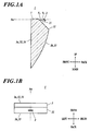
- FIG. 1A is a sectional side view of a vehicle lightening unit 1 according to an embodiment of the present invention
- FIG. 1B is a plan view of the lightening unit 1.
- the lightening unit 1 includes a light source 2 and a light guiding body 3, and emits light parallel to an optical axis Ax in the front direction.
- the light source 2 is composed of a light emitting element such as a light emitting diode.
- the light source 2 is disposed to emit light obliquely to the optical axis Ax in the front direction. More specifically, on a vertical sectional in the front/back direction of the lightening unit 1, an exit surface 21 of the light source 2 faces obliquely downward in the front direction in such a way that an angle ⁇ 1 between a central axis in a light emitting direction of the light source 2 and the optical axis Ax is 45 ⁇ 10°.
- the light guiding body 3 is a translucent member.
- the light guiding body 3 is disposed obliquely downward to the light source 2 in front of the light source 2.
- the light guiding body 3 receives light emitted from the light source 2, and guides the light in such a way as to be parallel to the optical axis Ax, and emits the light parallel to the optical axis Ax from the light guiding body 3.
- an incidence surface 31 is formed, the incidence surface through which the light emitted from the light source 2 enters the light guiding body 3.
- the incidence surface 31 faces the exit surface 21 of the light source 2 with a gap in between in such a way that on the vertical sectional in the front-back direction of the lightening unit 1, an angle ⁇ 2 between the incidence surface 31 and the optical axis Ax is 45+10° in order that the incidence surface 31 be almost parallel to the exit surface 21.
- a front surface 3a of the light guiding body 3 is a plane surface. In other words, the front surface 3a is curved in neither the up/down direction nor the right/left direction. As described below, the front surface 3a includes a first reflection surface 32 and an exit surface 34. By the first reflection surface 32, the light is internally reflected in the back direction, the light which enters the light guiding body 3 through the incidence surface 31. By the exit surface 34, the light is emitted from the light guiding body 3.
- a back surface 3b of the light guiding body 3 is a curved surface.
- the back surface 3b is curved to reach the lower end of the front surface 3a in such a way that the light guiding body 3 tapers to the lower end of the light guiding body 3 on the vertical section in the front/back direction of the lightening unit 1.
- the light guiding body 3 includes a second reflection surface 33 by which the light internally reflected by the first reflection surface 32 is internally reflected again in such a way that the light travels to the exit surface 34 while being parallel to the optical axis Ax.
- the light rays are further traced on the assumption that the light rays are totally reflected by the front surface 3a (first reflection surface 32) of the light guiding body 3.
- a first slope angle at a reflection point R is decided in such a way that a first light ray from the top among the traced light rays is totally reflected in the front direction so as to be parallel to the optical axis Ax.
- slope angles at their respective intersection points are decided successively. Then, the reflection point R, the intersection points, the lower end of the incidence surface 31, and the lower end of the front surface 3a are connected by a spline curve.
- the shape of the back surface 3b on the vertical section in the front/back direction of the light guiding body 3 is decided.
- the shape of the back surface 3b is the same in the right/left direction.
- the same condition, which is described above, is held on any vertical section in the front/back direction of the light guiding body 3 taken at any position in the right/left direction, the vertical section which includes the light rays as shown in FIG. 2B .
- the light source 2 emits light obliquely downward to the optical axis Ax in the front direction, and the light enters the light guiding body 3 through the incidence surface 31.
- the light is internally reflected by the front surface 3a (first reflection surface 32) of the light guiding body 3 in the back direction, internally reflected again by the back surface 3b (second reflection surface 33) of the light guiding body 3 in the front direction in such a way that the light is parallel to the optical axis Ax in the front direction when the light is emitted from the light guiding body 3, and thereafter, emitted from the light guiding body 3 through the front surface 3a (exit surface 34) thereof.
- the light which is parallel to the optical axis Ax can be obtained.
- the light source 2 emits light obliquely to the optical axis Ax in the front direction. Therefore, unlike a conventional lightening unit in which a light source faces straight ahead to the front of the lightening unit (in the light emitting direction), it is not necessary, in the lightening unit 1, to dispose the light guiding body 3 to cover the front of the light source 2 from above to below the light source 2. That is, the light emitted from the light source 2 can be efficiently taken in by the light guiding body 3 of the lighting unit 1.
- the light guiding body 3 of the lightening unit 1 can be manufactured to be smaller in the up/down direction and more compact than a conventional light guiding body of a conventional lightening unit.
- the change of the light guiding body 3 in thickness becomes less than a conventional guiding body, and hence, the light guiding body 3 can be more accurately manufactured than a conventional light guiding body. Consequently, manufacturing costs of the lightening unit 1 can be reduced.
- the light guiding body 3 can be manufactured to be smaller in the front/back direction and more compact than a conventional light guiding body from which the light is emitted after internally reflected only once.
- the incidence surface 31 of the light guiding body 3 faces the light source 2 with a gap in between. Accordingly, influence of heat on the light guiding body 3, the heat which is generated by the light source 2, can be reduced as compared with a conventional lightening unit in which a light guiding body touches a light source.
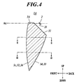
- FIG. 4 is a sectional side view of a vehicle lightening unit 1A according to the modification
- FIG. 5A is a sectional view taken along the line II-II of FIG. 4
- FIG. 5B is a sectional view taken along the line III-III of FIG. 4 .
- the lightening unit 1A includes a light guiding body 3A instead of the light guiding body 3 in the embodiment.
- a different between the light guiding body 3 in the embodiment and the light guiding body 3A in the modification is that while the light guiding body 3 has the front surface 3a which is plane, the light guiding body 3A has a front surface 3c which is curved in the up/down direction and in the right/left direction so as to be convex in the front direction. Because of the curved front surface 3c, the light guiding body 3A has a back surface 3d which is curved differently from the back surface 3b in the embodiment.
- an intersection point of a light ray traced from the light source 2 with a light ray traced in the back direction from the front surface 3c is obtained.
- a slope angle at the intersection point is decided in such a way that when the light ray is totally reflected at the intersection point, the light ray traced from the light source 2 becomes the light ray traced in the back direction from the front surface 3c, and vice versa.
- the shape of the back surface 3d on the vertical section in the front/back direction of the light guiding body 3 is decided.
- the back surface 3d In order to form the back surface 3d, it is necessary that the light rays which are traced from the light source 2 and next to each other are gradually separated from each other from the front surface 3c in the back direction, for example, as shown in FIG. 6C . Accordingly, the front surface 3c is required to fill that condition when formed. In addition, when the incidence surface 31 is curved, it is a matter of course that the incidence surface 31 is also required to fill the condition when formed.
- the effects obtained by the lightening unit 1 can be obtained by the lightening unit 1A too.
- the front surface 3a of the light guiding body 3 is plane, but may be curved in accordance with a desired light distribution pattern.
- a light distribution pattern D 1 can be obtained as shown in FIG. 8B .
- the light distribution pattern D 1 is narrower in the right/left direction (horizontal direction) than a light distribution pattern D 0 obtained when the front surface 3a is plane.
- a light distribution pattern D 2 can be obtained as shown in FIG. 9B .
- the light distribution pattern D 2 is wider in the right/left direction (horizontal direction) than the light distribution pattern D 0 obtained when the front surface 3a is plane.
- the light source 2 emits light obliquely downward to the optical axis Ax in the front direction.
- this is not a limit.
- the light source 2 may emit light obliquely sideward (rightward/leftward) to the optical axis in the front direction. In such a case, it is a matter of course to make other necessary changes in accordance with the change of the light emitting direction of the light source 2 so that the light guiding body 3 or 3A receives the light emitted from the light source 2.
- the first reflection surface 32 and the exit surface 34 are connected to be formed on one surface such as the front surface 3a or 3c.
- the first reflection surface 32 and the exit surface 34 may be formed on separate surfaces.
- the incidence surface 31 of the light guiding body 3 or 3A may be a plane surface as shown in the drawings, or may be a curved surface.
- a vehicle lighting unit which emits light parallel to an optical axis in a front direction
- the vehicle lighting unit including: a light source which emits the light obliquely to the optical axis in the front direction; and a light guiding body which guides the light emitted from the light source so as to emit the light
- the light guiding body including: an incidence surface disposed to face the light source with a gap in between, the incidence surface through which the light emitted from the light source enters the light guiding body; a front surface having an exit surface and a first reflection surface; and a back surface having a second reflection surface, wherein the light which enters the light guiding body through the incidence surface is internally reflected by the first reflection surface in a back direction, and the light which is internally reflected by the first reflection surface is internally reflected by the second reflection surface in the front direction to the exit surface so that the light is emitted from the light guiding body through the exit surface while the light is made to be
- the light source emits the light at 45 ⁇ 10 degrees to the optical axis.
- the first reflection surface is connected to the exit surface.
- the light source emits light obliquely to the optical axis in the front direction. Therefore, unlike a conventional lightening unit in which a light source faces straight ahead to the front of the lightening unit (in the light emitting direction) , it is not necessary, in the lightening unit, to dispose the light guiding body to cover the front of the light source from above to below the light source. That is, the light emitted from the light source can be efficiently taken in by the light guiding body of the lighting unit.
- the light guiding body of the lightening unit can be manufactured to be smaller in the up/down direction and more compact than a conventional light guiding body of a conventional lightening unit.
- the change of the light guiding body in thickness becomes less than a conventional guiding body, and hence, the light guiding body can be more accurately manufactured than a conventional light guiding body. Consequently, manufacturing costs of the lightening unit can be reduced.
- the light guiding body can be manufactured to be smaller in the front/back direction and more compact than a conventional light guiding body from which the light is emitted after internally reflected only once.
- the incidence surface of the light guiding body faces the light source with a gap in between. Accordingly, influence of heat on the light guiding body, the heat which is generated by the light source, can be reduced as compared with a conventional lightening unit in which a light guiding body touches a light source.
Landscapes
- Engineering & Computer Science (AREA)
- General Engineering & Computer Science (AREA)
- Physics & Mathematics (AREA)
- Geometry (AREA)
- Microelectronics & Electronic Packaging (AREA)
- Optics & Photonics (AREA)
- Non-Portable Lighting Devices Or Systems Thereof (AREA)
Applications Claiming Priority (1)
| Application Number | Priority Date | Filing Date | Title |
|---|---|---|---|
| JP2010116937A JP5562120B2 (ja) | 2010-05-21 | 2010-05-21 | 車両用灯具ユニット |
Publications (3)
| Publication Number | Publication Date |
|---|---|
| EP2388512A2 true EP2388512A2 (de) | 2011-11-23 |
| EP2388512A3 EP2388512A3 (de) | 2016-05-18 |
| EP2388512B1 EP2388512B1 (de) | 2018-11-21 |
Family
ID=44544103
Family Applications (1)
| Application Number | Title | Priority Date | Filing Date |
|---|---|---|---|
| EP11004206.6A Not-in-force EP2388512B1 (de) | 2010-05-21 | 2011-05-20 | Fahrzeugbeleuchtungseinheit |
Country Status (3)
| Country | Link |
|---|---|
| US (1) | US8529109B2 (de) |
| EP (1) | EP2388512B1 (de) |
| JP (1) | JP5562120B2 (de) |
Cited By (2)
| Publication number | Priority date | Publication date | Assignee | Title |
|---|---|---|---|---|
| EP2789900A2 (de) | 2013-04-11 | 2014-10-15 | Automotive Lighting Reutlingen GmbH | Lichtmodul für eine Kraftfahrzeugbeleuchtungseinrichtung |
| CN110296372A (zh) * | 2018-03-21 | 2019-10-01 | 嘉兴海拉灯具有限公司 | 一种光导、车灯及车辆 |
Families Citing this family (6)
| Publication number | Priority date | Publication date | Assignee | Title |
|---|---|---|---|---|
| JP5707661B2 (ja) | 2011-03-25 | 2015-04-30 | スタンレー電気株式会社 | 車両用灯具ユニット及び車両用灯具に用いられる導光体 |
| US9689546B2 (en) | 2011-03-25 | 2017-06-27 | Light Prescriptions Innovators, Llc | Vehicle lighting unit |
| JP5911397B2 (ja) * | 2012-07-31 | 2016-04-27 | スタンレー電気株式会社 | 車両用前照灯 |
| JP6250289B2 (ja) * | 2013-02-07 | 2017-12-20 | 株式会社小糸製作所 | 光学面決定方法 |
| DE102016101997A1 (de) * | 2016-02-04 | 2017-08-10 | SMR Patents S.à.r.l. | Beleuchtungseinrichtung und Rückblickeinrichtung für Fahrzeuge |
| JP6720809B2 (ja) * | 2016-09-29 | 2020-07-08 | オムロン株式会社 | 導光部材、導光部材ユニットおよび照明装置 |
Citations (4)
| Publication number | Priority date | Publication date | Assignee | Title |
|---|---|---|---|---|
| JP2005011704A (ja) | 2003-06-19 | 2005-01-13 | Koito Mfg Co Ltd | 灯具ユニットおよび車両用前照灯 |
| JP2007250233A (ja) | 2006-03-14 | 2007-09-27 | Koito Mfg Co Ltd | 車両用灯具ユニット |
| JP4108597B2 (ja) | 2003-12-24 | 2008-06-25 | 株式会社小糸製作所 | 車両用灯具ユニット |
| JP4113111B2 (ja) | 2003-12-24 | 2008-07-09 | 株式会社小糸製作所 | 車両用灯具ユニットおよび車両用照明灯具 |
Family Cites Families (16)
| Publication number | Priority date | Publication date | Assignee | Title |
|---|---|---|---|---|
| JP3544010B2 (ja) * | 1994-10-25 | 2004-07-21 | 本田技研工業株式会社 | 車両用灯火器 |
| JP2005158362A (ja) * | 2003-11-21 | 2005-06-16 | Stanley Electric Co Ltd | 車両用灯具 |
| JP4290601B2 (ja) * | 2004-05-17 | 2009-07-08 | 株式会社小糸製作所 | 車両用灯具ユニットおよび車両用灯具 |
| JP2006127856A (ja) * | 2004-10-27 | 2006-05-18 | Koito Mfg Co Ltd | 車両用照明灯具 |
| KR100694117B1 (ko) * | 2005-03-30 | 2007-03-12 | 삼성전자주식회사 | 조명유니트 및 이를 채용한 화상투사장치 |
| JP4468857B2 (ja) * | 2005-05-17 | 2010-05-26 | 株式会社小糸製作所 | 車両用照明灯具 |
| US7883249B2 (en) * | 2006-12-11 | 2011-02-08 | Toyoda Gosei Co., Ltd. | Lighting device for vehicle |
| JP4979565B2 (ja) * | 2007-12-14 | 2012-07-18 | 株式会社小糸製作所 | 車両用灯具 |
| JP5253888B2 (ja) * | 2008-02-22 | 2013-07-31 | 株式会社小糸製作所 | 車両用照明灯具 |
| US8136967B2 (en) * | 2008-03-02 | 2012-03-20 | Lumenetix, Inc. | LED optical lens |
| JP5168551B2 (ja) * | 2008-03-26 | 2013-03-21 | スタンレー電気株式会社 | 灯具用投影レンズ、車両用光学ユニット、及び、車両用灯具 |
| JP5445923B2 (ja) * | 2009-09-04 | 2014-03-19 | スタンレー電気株式会社 | 車両用灯具 |
| JP5516854B2 (ja) * | 2009-10-08 | 2014-06-11 | スタンレー電気株式会社 | 車両用灯具 |
| JP5779340B2 (ja) * | 2010-01-14 | 2015-09-16 | 株式会社小糸製作所 | 車両用灯具 |
| JP5498253B2 (ja) * | 2010-05-19 | 2014-05-21 | スタンレー電気株式会社 | 照明装置及びそのヒートシンク |
| JP5518607B2 (ja) * | 2010-07-08 | 2014-06-11 | 株式会社小糸製作所 | 車両用照明灯具 |
-
2010
- 2010-05-21 JP JP2010116937A patent/JP5562120B2/ja not_active Expired - Fee Related
-
2011
- 2011-05-20 EP EP11004206.6A patent/EP2388512B1/de not_active Not-in-force
- 2011-05-23 US US13/113,824 patent/US8529109B2/en not_active Expired - Fee Related
Patent Citations (4)
| Publication number | Priority date | Publication date | Assignee | Title |
|---|---|---|---|---|
| JP2005011704A (ja) | 2003-06-19 | 2005-01-13 | Koito Mfg Co Ltd | 灯具ユニットおよび車両用前照灯 |
| JP4108597B2 (ja) | 2003-12-24 | 2008-06-25 | 株式会社小糸製作所 | 車両用灯具ユニット |
| JP4113111B2 (ja) | 2003-12-24 | 2008-07-09 | 株式会社小糸製作所 | 車両用灯具ユニットおよび車両用照明灯具 |
| JP2007250233A (ja) | 2006-03-14 | 2007-09-27 | Koito Mfg Co Ltd | 車両用灯具ユニット |
Cited By (4)
| Publication number | Priority date | Publication date | Assignee | Title |
|---|---|---|---|---|
| EP2789900A2 (de) | 2013-04-11 | 2014-10-15 | Automotive Lighting Reutlingen GmbH | Lichtmodul für eine Kraftfahrzeugbeleuchtungseinrichtung |
| DE102013206488A1 (de) | 2013-04-11 | 2014-10-30 | Automotive Lighting Reutlingen Gmbh | Lichtmodul für eine Kraftfahrzeugbeleuchtungseinrichtung |
| US9599304B2 (en) | 2013-04-11 | 2017-03-21 | Automotive Lighting Reutlingen Gmbh | Light module for lighting equipment of a motor vehicle |
| CN110296372A (zh) * | 2018-03-21 | 2019-10-01 | 嘉兴海拉灯具有限公司 | 一种光导、车灯及车辆 |
Also Published As
| Publication number | Publication date |
|---|---|
| US8529109B2 (en) | 2013-09-10 |
| JP5562120B2 (ja) | 2014-07-30 |
| US20110286229A1 (en) | 2011-11-24 |
| EP2388512A3 (de) | 2016-05-18 |
| JP2011243521A (ja) | 2011-12-01 |
| EP2388512B1 (de) | 2018-11-21 |
Similar Documents
| Publication | Publication Date | Title |
|---|---|---|
| US8529109B2 (en) | Vehicle lightening unit | |
| US10036526B2 (en) | Light guiding lens and vehicle lighting unit | |
| CN106439670B (zh) | 具有两个反射面的透明材料发光模块 | |
| US10371341B2 (en) | Vehicle lamp | |
| JP6340751B2 (ja) | レンズ体及び車両用灯具 | |
| US9958124B2 (en) | Vehicular lamp | |
| US10078168B2 (en) | Vehicle lighting unit | |
| EP2957824B1 (de) | Fahrzeugbeleuchtungsvorrichtung | |
| US10088622B2 (en) | Light guiding lens and lighting unit | |
| EP3163155A1 (de) | Optisches streulichtverteilungssystem und fahrzeugbeleuchtungsvorrichtung | |
| US9033552B2 (en) | Light guide element for controlling light shape | |
| JP2012204167A (ja) | 車両用灯具ユニット | |
| EP3894743B1 (de) | Vorkollimator für eine beleuchtungsvorrichtung | |
| JP2017212070A (ja) | 車両用灯具 | |
| CN111174175A (zh) | 导光结构、发光组件、发光装置及车辆 | |
| CN106568068A (zh) | 导光透镜和光源模块 | |
| CN104456347B (zh) | 用于车辆的照明装置 | |
| JP5875905B2 (ja) | ドアミラー用サイドターンランプ | |
| JP6785673B2 (ja) | 車両用灯具 | |
| CN104154493A (zh) | 透镜和具有该透镜的照明装置 | |
| TWM508682U (zh) | 導光條結構 | |
| JP5786068B2 (ja) | 車両用灯具ユニット | |
| US11674661B2 (en) | Method for manufacturing light guiding plate, light guiding plate, and lighting tool for vehicle | |
| US10738959B2 (en) | Vehicular lamp fitting | |
| US7332747B2 (en) | Light-emitting diode for decoration |
Legal Events
| Date | Code | Title | Description |
|---|---|---|---|
| AK | Designated contracting states |
Kind code of ref document: A2 Designated state(s): AL AT BE BG CH CY CZ DE DK EE ES FI FR GB GR HR HU IE IS IT LI LT LU LV MC MK MT NL NO PL PT RO RS SE SI SK SM TR |
|
| AX | Request for extension of the european patent |
Extension state: BA ME |
|
| PUAI | Public reference made under article 153(3) epc to a published international application that has entered the european phase |
Free format text: ORIGINAL CODE: 0009012 |
|
| PUAL | Search report despatched |
Free format text: ORIGINAL CODE: 0009013 |
|
| AK | Designated contracting states |
Kind code of ref document: A3 Designated state(s): AL AT BE BG CH CY CZ DE DK EE ES FI FR GB GR HR HU IE IS IT LI LT LU LV MC MK MT NL NO PL PT RO RS SE SI SK SM TR |
|
| AX | Request for extension of the european patent |
Extension state: BA ME |
|
| RIC1 | Information provided on ipc code assigned before grant |
Ipc: F21S 8/10 20060101AFI20160412BHEP Ipc: F21S 8/12 20060101ALI20160412BHEP |
|
| RAP1 | Party data changed (applicant data changed or rights of an application transferred) |
Owner name: STANLEY ELECTRIC CO., LTD. Owner name: LIGHT PRESCRIPTIONS INNOVATORS, LLC |
|
| STAA | Information on the status of an ep patent application or granted ep patent |
Free format text: STATUS: REQUEST FOR EXAMINATION WAS MADE |
|
| 17P | Request for examination filed |
Effective date: 20161118 |
|
| RBV | Designated contracting states (corrected) |
Designated state(s): AL AT BE BG CH CY CZ DE DK EE ES FI FR GB GR HR HU IE IS IT LI LT LU LV MC MK MT NL NO PL PT RO RS SE SI SK SM TR |
|
| RIN1 | Information on inventor provided before grant (corrected) |
Inventor name: MINANO, JUAN CARLOS Inventor name: BENITEZ, PABLO Inventor name: MOHEDANO, RUBEN Inventor name: OHNO, MASAFUMI |
|
| RAP1 | Party data changed (applicant data changed or rights of an application transferred) |
Owner name: STANLEY ELECTRIC CO., LTD. |
|
| REG | Reference to a national code |
Ref country code: DE Ref legal event code: R079 Ref document number: 602011054004 Country of ref document: DE Free format text: PREVIOUS MAIN CLASS: F21S0008100000 Ipc: F21S0041147000 |
|
| GRAP | Despatch of communication of intention to grant a patent |
Free format text: ORIGINAL CODE: EPIDOSNIGR1 |
|
| STAA | Information on the status of an ep patent application or granted ep patent |
Free format text: STATUS: GRANT OF PATENT IS INTENDED |
|
| RIC1 | Information provided on ipc code assigned before grant |
Ipc: F21S 41/24 20180101ALI20180530BHEP Ipc: F21S 41/147 20180101AFI20180530BHEP Ipc: F21S 41/365 20180101ALI20180530BHEP |
|
| INTG | Intention to grant announced |
Effective date: 20180625 |
|
| GRAS | Grant fee paid |
Free format text: ORIGINAL CODE: EPIDOSNIGR3 |
|
| GRAA | (expected) grant |
Free format text: ORIGINAL CODE: 0009210 |
|
| STAA | Information on the status of an ep patent application or granted ep patent |
Free format text: STATUS: THE PATENT HAS BEEN GRANTED |
|
| AK | Designated contracting states |
Kind code of ref document: B1 Designated state(s): AL AT BE BG CH CY CZ DE DK EE ES FI FR GB GR HR HU IE IS IT LI LT LU LV MC MK MT NL NO PL PT RO RS SE SI SK SM TR |
|
| REG | Reference to a national code |
Ref country code: CH Ref legal event code: EP |
|
| REG | Reference to a national code |
Ref country code: IE Ref legal event code: FG4D |
|
| REG | Reference to a national code |
Ref country code: DE Ref legal event code: R096 Ref document number: 602011054004 Country of ref document: DE |
|
| REG | Reference to a national code |
Ref country code: AT Ref legal event code: REF Ref document number: 1067960 Country of ref document: AT Kind code of ref document: T Effective date: 20181215 |
|
| REG | Reference to a national code |
Ref country code: NL Ref legal event code: MP Effective date: 20181121 |
|
| REG | Reference to a national code |
Ref country code: AT Ref legal event code: MK05 Ref document number: 1067960 Country of ref document: AT Kind code of ref document: T Effective date: 20181121 |
|
| PG25 | Lapsed in a contracting state [announced via postgrant information from national office to epo] |
Ref country code: LV Free format text: LAPSE BECAUSE OF FAILURE TO SUBMIT A TRANSLATION OF THE DESCRIPTION OR TO PAY THE FEE WITHIN THE PRESCRIBED TIME-LIMIT Effective date: 20181121 Ref country code: FI Free format text: LAPSE BECAUSE OF FAILURE TO SUBMIT A TRANSLATION OF THE DESCRIPTION OR TO PAY THE FEE WITHIN THE PRESCRIBED TIME-LIMIT Effective date: 20181121 Ref country code: LT Free format text: LAPSE BECAUSE OF FAILURE TO SUBMIT A TRANSLATION OF THE DESCRIPTION OR TO PAY THE FEE WITHIN THE PRESCRIBED TIME-LIMIT Effective date: 20181121 Ref country code: BG Free format text: LAPSE BECAUSE OF FAILURE TO SUBMIT A TRANSLATION OF THE DESCRIPTION OR TO PAY THE FEE WITHIN THE PRESCRIBED TIME-LIMIT Effective date: 20190221 Ref country code: NO Free format text: LAPSE BECAUSE OF FAILURE TO SUBMIT A TRANSLATION OF THE DESCRIPTION OR TO PAY THE FEE WITHIN THE PRESCRIBED TIME-LIMIT Effective date: 20190221 Ref country code: AT Free format text: LAPSE BECAUSE OF FAILURE TO SUBMIT A TRANSLATION OF THE DESCRIPTION OR TO PAY THE FEE WITHIN THE PRESCRIBED TIME-LIMIT Effective date: 20181121 Ref country code: HR Free format text: LAPSE BECAUSE OF FAILURE TO SUBMIT A TRANSLATION OF THE DESCRIPTION OR TO PAY THE FEE WITHIN THE PRESCRIBED TIME-LIMIT Effective date: 20181121 Ref country code: IS Free format text: LAPSE BECAUSE OF FAILURE TO SUBMIT A TRANSLATION OF THE DESCRIPTION OR TO PAY THE FEE WITHIN THE PRESCRIBED TIME-LIMIT Effective date: 20190321 Ref country code: ES Free format text: LAPSE BECAUSE OF FAILURE TO SUBMIT A TRANSLATION OF THE DESCRIPTION OR TO PAY THE FEE WITHIN THE PRESCRIBED TIME-LIMIT Effective date: 20181121 |
|
| PG25 | Lapsed in a contracting state [announced via postgrant information from national office to epo] |
Ref country code: GR Free format text: LAPSE BECAUSE OF FAILURE TO SUBMIT A TRANSLATION OF THE DESCRIPTION OR TO PAY THE FEE WITHIN THE PRESCRIBED TIME-LIMIT Effective date: 20190222 Ref country code: PT Free format text: LAPSE BECAUSE OF FAILURE TO SUBMIT A TRANSLATION OF THE DESCRIPTION OR TO PAY THE FEE WITHIN THE PRESCRIBED TIME-LIMIT Effective date: 20190321 Ref country code: NL Free format text: LAPSE BECAUSE OF FAILURE TO SUBMIT A TRANSLATION OF THE DESCRIPTION OR TO PAY THE FEE WITHIN THE PRESCRIBED TIME-LIMIT Effective date: 20181121 Ref country code: RS Free format text: LAPSE BECAUSE OF FAILURE TO SUBMIT A TRANSLATION OF THE DESCRIPTION OR TO PAY THE FEE WITHIN THE PRESCRIBED TIME-LIMIT Effective date: 20181121 Ref country code: SE Free format text: LAPSE BECAUSE OF FAILURE TO SUBMIT A TRANSLATION OF THE DESCRIPTION OR TO PAY THE FEE WITHIN THE PRESCRIBED TIME-LIMIT Effective date: 20181121 Ref country code: AL Free format text: LAPSE BECAUSE OF FAILURE TO SUBMIT A TRANSLATION OF THE DESCRIPTION OR TO PAY THE FEE WITHIN THE PRESCRIBED TIME-LIMIT Effective date: 20181121 |
|
| PG25 | Lapsed in a contracting state [announced via postgrant information from national office to epo] |
Ref country code: CZ Free format text: LAPSE BECAUSE OF FAILURE TO SUBMIT A TRANSLATION OF THE DESCRIPTION OR TO PAY THE FEE WITHIN THE PRESCRIBED TIME-LIMIT Effective date: 20181121 Ref country code: PL Free format text: LAPSE BECAUSE OF FAILURE TO SUBMIT A TRANSLATION OF THE DESCRIPTION OR TO PAY THE FEE WITHIN THE PRESCRIBED TIME-LIMIT Effective date: 20181121 Ref country code: IT Free format text: LAPSE BECAUSE OF FAILURE TO SUBMIT A TRANSLATION OF THE DESCRIPTION OR TO PAY THE FEE WITHIN THE PRESCRIBED TIME-LIMIT Effective date: 20181121 Ref country code: DK Free format text: LAPSE BECAUSE OF FAILURE TO SUBMIT A TRANSLATION OF THE DESCRIPTION OR TO PAY THE FEE WITHIN THE PRESCRIBED TIME-LIMIT Effective date: 20181121 |
|
| REG | Reference to a national code |
Ref country code: DE Ref legal event code: R097 Ref document number: 602011054004 Country of ref document: DE |
|
| PG25 | Lapsed in a contracting state [announced via postgrant information from national office to epo] |
Ref country code: SM Free format text: LAPSE BECAUSE OF FAILURE TO SUBMIT A TRANSLATION OF THE DESCRIPTION OR TO PAY THE FEE WITHIN THE PRESCRIBED TIME-LIMIT Effective date: 20181121 Ref country code: SK Free format text: LAPSE BECAUSE OF FAILURE TO SUBMIT A TRANSLATION OF THE DESCRIPTION OR TO PAY THE FEE WITHIN THE PRESCRIBED TIME-LIMIT Effective date: 20181121 Ref country code: EE Free format text: LAPSE BECAUSE OF FAILURE TO SUBMIT A TRANSLATION OF THE DESCRIPTION OR TO PAY THE FEE WITHIN THE PRESCRIBED TIME-LIMIT Effective date: 20181121 Ref country code: RO Free format text: LAPSE BECAUSE OF FAILURE TO SUBMIT A TRANSLATION OF THE DESCRIPTION OR TO PAY THE FEE WITHIN THE PRESCRIBED TIME-LIMIT Effective date: 20181121 |
|
| PLBE | No opposition filed within time limit |
Free format text: ORIGINAL CODE: 0009261 |
|
| STAA | Information on the status of an ep patent application or granted ep patent |
Free format text: STATUS: NO OPPOSITION FILED WITHIN TIME LIMIT |
|
| 26N | No opposition filed |
Effective date: 20190822 |
|
| PG25 | Lapsed in a contracting state [announced via postgrant information from national office to epo] |
Ref country code: SI Free format text: LAPSE BECAUSE OF FAILURE TO SUBMIT A TRANSLATION OF THE DESCRIPTION OR TO PAY THE FEE WITHIN THE PRESCRIBED TIME-LIMIT Effective date: 20181121 |
|
| REG | Reference to a national code |
Ref country code: CH Ref legal event code: PL |
|
| PG25 | Lapsed in a contracting state [announced via postgrant information from national office to epo] |
Ref country code: LI Free format text: LAPSE BECAUSE OF NON-PAYMENT OF DUE FEES Effective date: 20190531 Ref country code: MC Free format text: LAPSE BECAUSE OF FAILURE TO SUBMIT A TRANSLATION OF THE DESCRIPTION OR TO PAY THE FEE WITHIN THE PRESCRIBED TIME-LIMIT Effective date: 20181121 Ref country code: CH Free format text: LAPSE BECAUSE OF NON-PAYMENT OF DUE FEES Effective date: 20190531 |
|
| REG | Reference to a national code |
Ref country code: BE Ref legal event code: MM Effective date: 20190531 |
|
| PG25 | Lapsed in a contracting state [announced via postgrant information from national office to epo] |
Ref country code: LU Free format text: LAPSE BECAUSE OF NON-PAYMENT OF DUE FEES Effective date: 20190520 |
|
| PG25 | Lapsed in a contracting state [announced via postgrant information from national office to epo] |
Ref country code: TR Free format text: LAPSE BECAUSE OF FAILURE TO SUBMIT A TRANSLATION OF THE DESCRIPTION OR TO PAY THE FEE WITHIN THE PRESCRIBED TIME-LIMIT Effective date: 20181121 |
|
| PG25 | Lapsed in a contracting state [announced via postgrant information from national office to epo] |
Ref country code: IE Free format text: LAPSE BECAUSE OF NON-PAYMENT OF DUE FEES Effective date: 20190520 |
|
| PG25 | Lapsed in a contracting state [announced via postgrant information from national office to epo] |
Ref country code: BE Free format text: LAPSE BECAUSE OF NON-PAYMENT OF DUE FEES Effective date: 20190531 |
|
| PG25 | Lapsed in a contracting state [announced via postgrant information from national office to epo] |
Ref country code: CY Free format text: LAPSE BECAUSE OF FAILURE TO SUBMIT A TRANSLATION OF THE DESCRIPTION OR TO PAY THE FEE WITHIN THE PRESCRIBED TIME-LIMIT Effective date: 20181121 |
|
| PG25 | Lapsed in a contracting state [announced via postgrant information from national office to epo] |
Ref country code: HU Free format text: LAPSE BECAUSE OF FAILURE TO SUBMIT A TRANSLATION OF THE DESCRIPTION OR TO PAY THE FEE WITHIN THE PRESCRIBED TIME-LIMIT; INVALID AB INITIO Effective date: 20110520 Ref country code: MT Free format text: LAPSE BECAUSE OF FAILURE TO SUBMIT A TRANSLATION OF THE DESCRIPTION OR TO PAY THE FEE WITHIN THE PRESCRIBED TIME-LIMIT Effective date: 20181121 |
|
| PG25 | Lapsed in a contracting state [announced via postgrant information from national office to epo] |
Ref country code: MK Free format text: LAPSE BECAUSE OF FAILURE TO SUBMIT A TRANSLATION OF THE DESCRIPTION OR TO PAY THE FEE WITHIN THE PRESCRIBED TIME-LIMIT Effective date: 20181121 |
|
| REG | Reference to a national code |
Ref country code: FR Ref legal event code: PLFP Year of fee payment: 13 |
|
| PGFP | Annual fee paid to national office [announced via postgrant information from national office to epo] |
Ref country code: GB Payment date: 20230330 Year of fee payment: 13 |
|
| PGFP | Annual fee paid to national office [announced via postgrant information from national office to epo] |
Ref country code: FR Payment date: 20230411 Year of fee payment: 13 Ref country code: DE Payment date: 20230331 Year of fee payment: 13 |
|
| REG | Reference to a national code |
Ref country code: DE Ref legal event code: R119 Ref document number: 602011054004 Country of ref document: DE |
|
| GBPC | Gb: european patent ceased through non-payment of renewal fee |
Effective date: 20240520 |
|
| PG25 | Lapsed in a contracting state [announced via postgrant information from national office to epo] |
Ref country code: DE Free format text: LAPSE BECAUSE OF NON-PAYMENT OF DUE FEES Effective date: 20241203 |
|
| PG25 | Lapsed in a contracting state [announced via postgrant information from national office to epo] |
Ref country code: FR Free format text: LAPSE BECAUSE OF NON-PAYMENT OF DUE FEES Effective date: 20240531 |
|
| PG25 | Lapsed in a contracting state [announced via postgrant information from national office to epo] |
Ref country code: GB Free format text: LAPSE BECAUSE OF NON-PAYMENT OF DUE FEES Effective date: 20240520 |