EP2388538A2 - Montagefuss für Solarmodule - Google Patents
Montagefuss für Solarmodule Download PDFInfo
- Publication number
- EP2388538A2 EP2388538A2 EP11163471A EP11163471A EP2388538A2 EP 2388538 A2 EP2388538 A2 EP 2388538A2 EP 11163471 A EP11163471 A EP 11163471A EP 11163471 A EP11163471 A EP 11163471A EP 2388538 A2 EP2388538 A2 EP 2388538A2
- Authority
- EP
- European Patent Office
- Prior art keywords
- module plate
- mounting foot
- mounting
- edge
- module
- Prior art date
- Legal status (The legal status is an assumption and is not a legal conclusion. Google has not performed a legal analysis and makes no representation as to the accuracy of the status listed.)
- Withdrawn
Links
- 239000000758 substrate Substances 0.000 abstract description 3
- 238000009434 installation Methods 0.000 description 3
- 239000004033 plastic Substances 0.000 description 3
- 229920003023 plastic Polymers 0.000 description 3
- 230000001154 acute effect Effects 0.000 description 2
- 238000003780 insertion Methods 0.000 description 2
- 230000037431 insertion Effects 0.000 description 2
- 229920002430 Fibre-reinforced plastic Polymers 0.000 description 1
- 229910000831 Steel Inorganic materials 0.000 description 1
- 229910052782 aluminium Inorganic materials 0.000 description 1
- XAGFODPZIPBFFR-UHFFFAOYSA-N aluminium Chemical compound [Al] XAGFODPZIPBFFR-UHFFFAOYSA-N 0.000 description 1
- 238000006243 chemical reaction Methods 0.000 description 1
- 230000007613 environmental effect Effects 0.000 description 1
- 239000011151 fibre-reinforced plastic Substances 0.000 description 1
- 238000004519 manufacturing process Methods 0.000 description 1
- 229910052751 metal Inorganic materials 0.000 description 1
- 239000002184 metal Substances 0.000 description 1
- 230000000630 rising effect Effects 0.000 description 1
- 239000010959 steel Substances 0.000 description 1
Images

Classifications
-
- F—MECHANICAL ENGINEERING; LIGHTING; HEATING; WEAPONS; BLASTING
- F24—HEATING; RANGES; VENTILATING
- F24S—SOLAR HEAT COLLECTORS; SOLAR HEAT SYSTEMS
- F24S25/00—Arrangement of stationary mountings or supports for solar heat collector modules
- F24S25/60—Fixation means, e.g. fasteners, specially adapted for supporting solar heat collector modules
- F24S25/61—Fixation means, e.g. fasteners, specially adapted for supporting solar heat collector modules for fixing to the ground or to building structures
- F24S25/617—Elements driven into the ground, e.g. anchor-piles; Foundations for supporting elements; Connectors for connecting supporting structures to the ground or to flat horizontal surfaces
-
- F—MECHANICAL ENGINEERING; LIGHTING; HEATING; WEAPONS; BLASTING
- F24—HEATING; RANGES; VENTILATING
- F24S—SOLAR HEAT COLLECTORS; SOLAR HEAT SYSTEMS
- F24S25/00—Arrangement of stationary mountings or supports for solar heat collector modules
- F24S25/10—Arrangement of stationary mountings or supports for solar heat collector modules extending in directions away from a supporting surface
- F24S25/16—Arrangement of interconnected standing structures; Standing structures having separate supporting portions for adjacent modules
-
- F—MECHANICAL ENGINEERING; LIGHTING; HEATING; WEAPONS; BLASTING
- F24—HEATING; RANGES; VENTILATING
- F24S—SOLAR HEAT COLLECTORS; SOLAR HEAT SYSTEMS
- F24S25/00—Arrangement of stationary mountings or supports for solar heat collector modules
- F24S2025/80—Special profiles
-
- Y—GENERAL TAGGING OF NEW TECHNOLOGICAL DEVELOPMENTS; GENERAL TAGGING OF CROSS-SECTIONAL TECHNOLOGIES SPANNING OVER SEVERAL SECTIONS OF THE IPC; TECHNICAL SUBJECTS COVERED BY FORMER USPC CROSS-REFERENCE ART COLLECTIONS [XRACs] AND DIGESTS
- Y02—TECHNOLOGIES OR APPLICATIONS FOR MITIGATION OR ADAPTATION AGAINST CLIMATE CHANGE
- Y02E—REDUCTION OF GREENHOUSE GAS [GHG] EMISSIONS, RELATED TO ENERGY GENERATION, TRANSMISSION OR DISTRIBUTION
- Y02E10/00—Energy generation through renewable energy sources
- Y02E10/40—Solar thermal energy, e.g. solar towers
- Y02E10/47—Mountings or tracking
Definitions
- the invention relates to a mounting foot for solar modules with a variable receptacle for a module plate.
- this mounting system In order to avoid damage to the roof or flat roof roofs sensitive roofing, this mounting system is usually installed without direct attachment or connection to the building. The securing of the mounting system against shifting or lifting takes place via ballast, whereby, however, the maximum load of the flat roof is to be observed.
- the mounting system serving as a substructure thus forms a roof attachment to which the solar modules are fastened at a desired angle of inclination. Depending on the geographical position of the building and the inclination of the roof, the ideal angle of inclination varies for the highest possible efficiency of the solar modules.
- the object of the invention is to provide a simple and inexpensive producible mounting foot, which can be used for different angles of inclination of the solar system and for different thicknesses of the individual solar modules.
- this object is achieved by a mounting foot for solar modules with a base body which has at least one footprint with which the mounting foot can support the ground, and with a variable receptacle for a module plate, the V-shaped fork bearing for receiving an edge of the Module plate is formed.
- the invention is based on the realization that with a single mounting foot having no adjustable components, different tilt angles can be achieved and differently thick solar modules can be accommodated by using a fork bearing which expands towards an open end.
- the solar module can be inserted with an edge into the fork bearing until the solar module rests with one edge on each of the upper and lower fork sides.
- the mounting foot can be used for various panel thicknesses.
- a thicker plate lies farther out on the fork sides, while a thinner plate can be pushed farther into the fork bearing until the edges abut the fork sides.
- the module plate can also be used at different angles of inclination in the recording, the edges of the module plate each rest at different contact points on both the upper and on the lower fork side and are held securely.
- the inclination angle can be varied between the inclination angle of the two fork sides.
- the solar module lies flat on a fork side and with an edge of the opposite surface on the second fork side. Between these extremes, the module plate can be pivoted as desired, since the solar module rests in each case on the two inner sides of the fork and is thus held securely.
- the fork bearing preferably has an upper contact surface and a lower contact surface for the edge of the module plate, which are arranged opposite one another on the inside of the fork bearing.
- the edges of the module plate are each on the contact surfaces and can be moved to this, so that the angle of the module plate can be adjusted continuously.
- the mounting foot must therefore accommodate an inclined module plate in order to achieve an ideal efficiency of the solar modules.
- Only the exact angle of inclination must be adjusted depending on the geographical location and a possible inclination of the roof. Therefore, the upper abutment surface and the lower abutment surface are preferably inclined to the standing surface of the main body, and the inclination angle of the upper abutment surface is greater than the inclination angle of the lower abutment surface. As a result, the angle of inclination of the module plate can be adjusted in as large a range as possible.
- a projecting in the direction of the upper contact surface, in particular parallel to the edge of the module plate extending projection is provided on the lower bearing surface, on which the module plate rests.
- the projection serves as a support point by which the module plate can be pivoted. Since the module plate is held by the projection spaced from the lower abutment surface, the inclination angle is not limited by the lower abutment surface.
- the projection serves as a pivot point, which allows a simpler tilt angle adjustment of the module plate.
- the fork bearing for example, a stop for the edge of the module plate.
- the mounting foot can for example have a lower support for a first inclined module plate and an upper support for a second module plate.
- the fork bearing is preferably provided on the lower support of the mounting foot.
- the feet are positioned so that a first mounting foot can accommodate the lower edge of a module plate with the designed as a fork bearing lower support.
- a second mounting foot can accommodate the upper edge of the module plate with the upper support.
- the lower support of the second mounting foot serves as a receptacle for a second module plate.
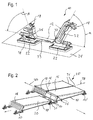
- the FIG. 1 shows a mounting base 10 for solar modules, with a base body 12, connected to the base 12 upper support 14 for a first inclined module plate 16 and connected to the base 12 lower support 18 for a non-modulatory to the first module plate 16, second inclined module plate 20.
- the base body 12 has at least one base 22, with which the mounting foot 10 on a substrate 24, for example a roof of a flat roof, can be supported.
- the upper support 14 has a greater distance to a plane spanned by the support surfaces 22 level than the lower support 18th
- FIG. 2 a section of a solar system 25 shown with a mounting system 26 for solar modules, wherein the present mounting system 26 is a flat roof mounting system with a corresponding horizontal surface 24 and a plurality of mounting feet 10 according to FIG. 1 having.
- the mounting system 26 forms together with the module plates 16, 20 formed as solar modules, the solar system 25 except on flat roofs is a use of Mounting system 26 also conceivable on pitch roofs with low roof pitch or other ground 24 with low inclination.
- the mounting system 26 comprises a plurality of inclined or tilted relative to a plane defined by the base surface 22 solar modules, which according to FIG. 2 are divided into two rows of solar modules with first module plates 16 and second module plates 20, wherein in FIG. 2 only a second module plate 20 is shown.
- all module plates 16, 20 which are arranged coplanar, that is to say lying in one plane, are referred to as the solar module row.
- the module plates 16, 20 of two different rows of solar modules are arranged non-coplanar and are correspondingly in different, albeit mostly substantially parallel planes.
- the inclination or inclination of the solar modules is usually oriented so that an upper side of the solar modules, at least in the northern hemisphere, faces south.
- a direction of inclination of the solar modules is defined as the longitudinal direction 28 of the mounting system 26, so that the longitudinal direction 28 in a completed solar system 25 according to FIG. 2 usually corresponds to the north-south direction.
- a solar module row extends in a transverse direction 30, which usually corresponds to the west-east direction.
- both legs 32, 34 for the supports 14, 18 each have an acute angle ⁇ , ⁇ with the base 22, wherein the legs 32, 34 in the longitudinal direction 28 are directed away from each other.
- the leg 32 of the upper support 14 is directed away from the leg 34 and includes an acute (Anstell-) angle ⁇ , that is an angle of 0 ° ⁇ ⁇ 90 ° with the base 22 a. Due to the dynamic pressure occurring in a wind load, the angle of attack ⁇ of the leg 32 is preferably between 50 ° and 80 °. Angle of incidence ⁇ ⁇ 90 ° are conceivable in principle, but for the above-mentioned reason only makes sense in exceptional cases.
- the leg 34 of the lower support 18 is usually so short that its angle of attack ⁇ has no appreciable influence on the mounting system 26. Therefore, the in FIG. 1 drawn angle ⁇ of the leg 34 also assume values of ⁇ ⁇ 90 °.
- the main body 12 of the mounting foot 10 comprises a first base portion 37 with a leg 32 having the upper support 14, a second base portion 38 having a leg 34 having the lower support 18 and a connecting web 39 between the base body portions 37, 38, the support surface 22 being interrupted in the region of the connecting web 39 ,
- this embodiment provides locally very uneven ground 24 the advantage of greater stability due to less tendency to tilt.
- the mounting system 26 points in FIG. 2 a plurality of mounting feet 10 arranged one behind the other in the longitudinal direction 28 for supporting the front edge 36 of a module plate 16, 20 on the lower support 18 of a front mounting foot 10 and a rear edge 48 of this module plate 16, 20 on the upper support 14 of a rear mounting foot 10.
- the mounting system 26 comprises longitudinal connecting struts 49 for connecting two mounting feet 10 adjacent in the longitudinal direction 28 and cross connecting struts 52 for connecting two mounting feet 10 adjacent in the transverse direction 30
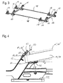
- FIG. 3 refer to, in which a section of the mounting system 26 is shown.
- the individual mounting feet 10 according to FIG. 1 each have offset supports 14, 18 for up to four module plates 16, 20, wherein in the corner and edge regions of the mounting system 26 only one or two supports 14, 18 are used.
- correspondingly adapted mounting feet 10 ' are used, which consist essentially only of the second main body portion 38 with the front supports 18 (see. FIG. 2 ).
- the free end of the leg 34 is formed with the lower support 18 as a fork bearing 50 for receiving a (seen from the south) front edge 36 of the module plate 16, 20 (see also FIG. 2 ).
- the fork bearing 50 is designed so that it allows a limited pivoting of the module plate 16, 20 to the lower support 18 so that the mounting base 10 can be used in identical design for different angles of inclination of the solar modules.
- the fork bearing 50 has a arranged on the upper fork side 52 upper contact surface 54 and provided on the lower fork side 56 lower abutment surface 58, which are arranged opposite to the inside of the fork bearing 50.
- the fork sides 52, 56 expand toward their free end, so that the fork bearing is V-shaped.
- Both the upper abutment surface 54 and the lower abutment surface 58 have an inclination angle .gamma. Or .DELTA. To the plane spanned by the standing surface 22, wherein the inclination angle .gamma. Of the lower abutment surface 58 is smaller than the inclination angle .gamma. Of the upper abutment surface 54. Both inclination angles ⁇ , ⁇ lie here between 0 and 90 °, but it is conceivable in principle that they are smaller than 0 or greater than 90 °.
- a projection 60 projecting in the direction of the upper abutment surface 54 is furthermore provided, which extends in the transverse direction over the entire width of the abutment surface 58.
- a stop 62 is also provided, which prevents too much insertion into the fork bearing 50, in particular with thinner module plates 16, 20.
- module plate 16, 20 An inserted into the fork bearing 50 module plate 16, 20 abuts with an adjacent to the top of the module plate edge 64 at a contact point 66 on the upper abutment surface 54. With the bottom, the module plate 16, 20 on the projection 60 of the lower contact surface 58. As a result, it is securely held between the fork sides 52, 56.
- a thicker module plate 16 ', 20' can not be pushed so far into the fork bearing 50 and is accordingly with the upper edge 64 'at a contact point 66' on the upper contact surface 54, which is closer to the open end of the fork bearing 50.
- a storage of different thickness module plates 16, 20 is possible.
- a storage of module plates 16, 20 with a thickness of 35 - 50mm is possible.
- the fork bearing 50 also allows the mounting of a module plate 16, 20 with different inclination angle of the module plate 16, 20.
- the projection 60 serves as a fulcrum around which the module plate 16, 20 can be pivoted. That is, the module plate is always on the bottom of the projection 60 and is pivoted about this. Once the desired angle of inclination has been reached, the module plate 16, 20 can be pushed into the fork bearing 50 until the upper edge 64 abuts against the upper contact surface 54. By the projection 60 while the pivoting movement is facilitated. On the other hand, the adjustment range of the inclination angle of the module plate 16, 20 is increased.
- the adjustment range of the inclination angle by the inclination angle ⁇ , ⁇ of the contact surfaces 54, 58 would be limited.
- the module plate 16, 20 would rest with the underside on the lower abutment surface 58 or on the upper abutment surface 54 with the upper side.
- the module plate 16, 20 are also installed with an inclination angle which is shallower than the inclination angle ⁇ of the lower abutment surface 58th
- the mounting of a module plate 16, 20 is exemplary in FIG. 5 shown.
- the module plate 16, 20 is placed in a relatively steep angle in the fork bearing 50 of the lower support 18. Subsequently, we the module plate 16, 20 in the fork bearing 50 so far pivoted until the rear edge of the module plate 16, 20 rests on the upper support of a second mounting base 10 and the rear edge of the module plate 16, 20 with a clamp or other suitable fastening means at the top Support 14 fixed. In this position, the module plate 16, 20 is located on the lower contact surface 58, here on the projection 60 and on the upper contact surface 54, and is held securely.
- the mounting foot 10 is preferably made in one piece from plastic, in particular fiber-reinforced plastic. From plastics it is also possible to produce relatively complex geometric shapes such as the mounting foot 10 with relatively little effort. Furthermore, 10 suitable plastics with sufficient strength, durability and weather resistance are comparatively inexpensive available for the mounting base, so that the mounting foot 10 can be made very cost overall. Alternatively, of course, a one-piece or multi-part production of the mounting foot 10 made of metal, in particular steel or aluminum conceivable.
Landscapes
- Engineering & Computer Science (AREA)
- Physics & Mathematics (AREA)
- Life Sciences & Earth Sciences (AREA)
- Sustainable Development (AREA)
- Sustainable Energy (AREA)
- Thermal Sciences (AREA)
- Chemical & Material Sciences (AREA)
- Combustion & Propulsion (AREA)
- Mechanical Engineering (AREA)
- General Engineering & Computer Science (AREA)
- Photovoltaic Devices (AREA)
- Roof Covering Using Slabs Or Stiff Sheets (AREA)
Abstract
Ein Montagefuß (10) für Solarmodule weist eine Grundkörper (12) auf, der wenigstens eine Standfläche (22) hat, mit welcher sich der Montagefuß (10) am Untergrund (24) abstützen kann, sowie eine variable Aufnahme für eine Modulplatte (16, 20), die als V-förmiges Gabellager (50) zur Aufnahme eines Randes der Modulplatte (16, 20) ausgebildet ist.
Description
- Die Erfindung betrifft einen Montagefuß für Solarmodule mit einer variablen Aufnahme für eine Modulplatte.
- Solaranlagen erfreuen sich derzeit angesichts steigender Energiekosten, zahlreicher Förderprogramme für regenerative Energien und aktueller Diskussionen über die Folgen eines globalen Klimawandels sowohl aus ökonomischen als auch ökologischen Gründen wachsender Beliebtheit. Eigentümer von für Solaranlagen geeigneten Immobilien sind dabei stets bestrebt, den maximalen Energieertrag bei möglichst geringen Investitionen in die Solaranlage sowie einen solargerechten Umbau des Gebäudes zu erzielen.
- Es hat sich gezeigt, dass Flachdächer für eine Nutzung durch Solaranlagen besonders geeignet sind, da in der Regel keine oder lediglich minimale bauliche Anpassungen am Gebäude selbst notwendig sind. Üblicherweise wird als Unterkonstruktion lediglich ein Montagesystem aufgestellt, um die Solarmodule schräg zu stellen und auf der Nordhalbkugel nach Süden hin auszurichten, wodurch der Wirkungsgrad und damit die Energieausbeute der Solaranlage deutlich ansteigen.
- Um Schäden an der Dachhaut oder der bei Flachdächern empfindlichen Dachabdichtung zu vermeiden, wird dieses Montagesystem üblicherweise installiert, ohne eine direkte Befestigung oder Verbindung zum Gebäude herzustellen. Die Sicherung des Montagesystems gegen Verschieben oder Abheben erfolgt über Ballast, wobei jedoch die maximale Traglast des Flachdachs zu beachten ist. Das als Unterkonstruktion dienende Montagesystem bildet somit einen Dachaufsatz, an dem die Solarmodule unter einem gewünschten Neigungswinkel befestigt werden. Abhängig von der geografischen Lage des Gebäudes und der Neigung des Daches variiert der für einen möglichst hohen Wirkungsgrad der Solarmodule ideale Neigungswinkel.
- Aufgabe der Erfindung ist es, einen möglichst einfachen und preiswert herstellbaren Montagefuß zu schaffen, der für verschiedene Neigungswinkels des Solarsystems und für verschiedene Dicken der einzelnen Solarmodule einsetzbar ist.
- Erfindungsgemäß wird diese Aufgabe gelöst durch einen Montagefuß für Solarmodule mit einem Grundkörper, der wenigstens eine Standfläche hat, mit welcher sich der Montagefuß am Untergrund abstützen kann, und mit einer variablen Aufnahme für eine Modulplatte, die als V-förmiges Gabellager zur Aufnahme eines Randes der Modulplatte ausgebildet ist. Die Erfindung beruht auf der Erkenntnis, dass mit einem einzigen Montagefuß, der keine einstellbaren Bauteile aufweist, unterschiedliche Neigungswinkel erzielt und unterschiedlich dicke Solarmodule aufgenommen werden können, indem ein Gabellager verwendet wird, das sich zu einem offenen Ende hin aufweitet. Das Solarmodul kann mit einem Rand in das Gabellager eingeschoben werden, bis das Solarmodul jeweils mit einer Kante an der oberen und der unteren Gabelseite anliegt. Der Montagefuß kann zum einen für verschiedene Plattendicken verwendet werden. Eine dickere Platte liegt weiter außen an den Gabelseiten an, während eine dünnere Platte weiter in das Gabellager eingeschoben werden kann, bis die Kanten an den Gabelseiten anliegen. Die Modulplatte kann ebenso in verschiedenen Neigungswinkel in die Aufnahme eingesetzt werden, wobei die Kanten der Modulplatte jeweils an unterschiedlichen Anlagepunkten sowohl an der oberen als auch an der unteren Gabelseite anliegen und so sicher gehalten sind. Der Neigungswinkel kann dabei zwischen den Neigungswinkel der beiden Gabelseiten variiert werden. Im Extremfall liegt das Solarmodul flach auf einer Gabelseite auf und mit einer Kante der gegenüberliegenden Fläche an der zweiten Gabelseite an. Zwischen diesen Extremen kann die Modulplatte beliebig verschwenkt werden, da das Solarmodul jeweils an den beiden Gabelinnenseiten anliegt und so sicher gehalten ist.
- Das Gabellager weist dafür vorzugsweise eine obere Anlagefläche und eine untere Anlagefläche für den Rand der Modulplatte auf, die gegenüberliegend auf der Innenseite des Gabellagers angeordnet sind. Die Kanten der Modulplatte liegen jeweils an den Anlageflächen an und können auf diesen verschoben werden, so dass der Winkel der Modulplatte stufenlos eingestellt werden kann.
- Solarmodule werden üblicherweise schräggestellt nach Süden ausgerichtet. Der Montagefuß muss also in jedem Fall eine schräggestellte Modulplatte aufnehmen, um einen idealen Wirkungsgrad der Solarmodule zu erzielen. Lediglich der genaue Neigungswinkel muss abhängig von der geografischen Lage und einer eventuellen Dachneigung angepasst werden. Die obere Anlagefläche und die untere Anlagefläche sind deshalb vorzugsweise zur Standfläche des Grundkörpers geneigt, und der Neigungswinkel der oberen Anlagefläche ist größer als der Neigungswinkel der unteren Anlagefläche. Dadurch kann der Neigungswinkel der Modulplatte in einem möglichst großen Bereich verstellt werden.
- Um den Einstellbereich des Neigungswinkels der Modulplatte zu vergrößern, ist an der unteren Anlagefläche ein in Richtung zur oberen Anlagefläche ragender, insbesondere parallel zum Rand der Modulplatte verlaufender Vorsprung vorgesehen, auf dem die Modulplatte aufliegt. Der Vorsprung dient als Auflagepunkt, um den die Modulplatte verschwenkt werden kann. Da die Modulplatte durch den Vorsprung beabstandet von der unteren Anlagefläche gehalten ist, ist der Neigungswinkel nicht durch die untere Anlagefläche begrenzt. Zudem dient der Vorsprung als Schwenkpunkt, der eine einfachere Neigungswinkelverstellung der Modulplatte ermöglicht.
- Um ein zu weites Einschieben einer dünneren Modulplatte und dadurch ein eventuelles Verklemmen der Modulplatte im Montagefuß zu verhindern, weist das Gabellager beispielsweise einen Anschlag für den Rand der Modulplatte auf.
- Der Montagefuß kann beispielsweise ein unteres Auflager für eine erste schräggestellte Modulplatte aufweisen und ein oberes Auflager für eine zweite Modulplatte. Das Gabellager ist vorzugsweise am unteren Auflager des Montagefußes vorgesehen. Für die Installation einer Solaranlage können so mehrere hintereinander angeordnete Montagefüße verwendet werden. Die Füße werden so positioniert, dass ein erster Montagefuß mit dem als Gabellager ausgebildeten unteren Auflager den unteren Rand einer Modulplatte aufnehmen kann. Ein zweiter Montagefuß kann mit dem oberen Auflager den oberen Rand der Modulplatte aufnehmen. Das untere Auflager des zweiten Montagefußes dient als Aufnahme für eine zweite Modulplatte. Die Montage der gesamten Solaranlage kann so mit nur einer Sorte Montagefüße erfolgen, so dass die Montagekosten sowie die Montagezeit reduziert werden können.
- Weitere Vorteile und Merkmale ergeben sich aus der nachfolgenden Beschreibung in Verbindung mit den beigefügten Zeichnungen. In diesen zeigen:
-
Figur 1 eine perspektivische Ansicht eines erfindungsgemäßen Montagefußes für Solarmodule; -
Figur 2 eine perspektivische Ansicht einer Solaranlage mit mehreren erfindungsgemäßen Montagefüßen; -
Figur 3 einen Ausschnitt der Solaranlage ausFigur 2 in perspektivischer Ansicht; -
Figur 4 eine Detailansicht des erfindungsgemäßen Montagefußes im Bereich des Gabellagers; und -
Figur 5 die Montage einer Modulplatte in einem erfindungsgemäßen Montagefuß. - Die
Figur 1 zeigt einen Montagefuß 10 für Solarmodule, mit einem Grundkörper 12, einem mit dem Grundkörper 12 verbundenen oberen Auflager 14 für eine erste schräggestellte Modulplatte 16 und einem mit dem Grundkörper 12 verbundenen unteren Auflager 18 für eine zur ersten Modulplatte 16 nichtkoplanare, benachbarte, zweite schräggestellte Modulplatte 20. Der Grundkörper 12 hat wenigstens eine Standfläche 22, mit welcher sich der Montagefuß 10 an einem Untergrund 24, zum Beispiel einer Dachhaut eines Flachdachs, abstützen kann. Das obere Auflager 14 weist dabei einen größeren Abstand zu einer von den Standflächen 22 aufgespannten Ebene auf als das untere Auflager 18. - Um die Funktion und Verwendung eines solchen Montagefußes 10 sowie den Unterschied zwischen ersten und zweiten Modulplatten 16, 20 zu verdeutlichen, ist in
Figur 2 ein Ausschnitt einer Solaranlage 25 mit einem Montagesystem 26 für Solarmodule dargestellt, wobei das vorliegende Montagesystem 26 ein Flachdach-Montagesystem mit entsprechend horizontalem Untergrund 24 ist und mehrere Montagefüße 10 gemäßFigur 1 aufweist. Das Montagesystem 26 bildet zusammen mit den als Modulplatten 16, 20 ausgebildeten Solarmodulen die Solaranlage 25. Außer auf Flachdächern ist eine Verwendung des Montagesystems 26 auch auf Pultdächern mit geringer Dachneigung oder einem anderen Untergrund 24 mit geringer Neigung denkbar. - Das Montagesystem 26 umfasst mehrere relativ zu einer von der Standfläche 22 aufgespannten Ebene geneigte oder schräggestellte Solarmodule, welche gemäß
Figur 2 in zwei Solarmodulreihen mit ersten Modulplatten 16 und zweiten Modulplatten 20 aufgeteilt sind, wobei inFigur 2 nur eine zweite Modulplatte 20 gezeigt ist. Als Solarmodulreihe werden dabei alle Modulplatten 16, 20 bezeichnet, welche koplanar, das heißt in einer Ebene liegend, angeordnet sind. Die Modulplatten 16, 20 zweier unterschiedlicher Solarmodulreihen sind hingegen nicht-koplanar angeordnet und liegen entsprechend in unterschiedlichen, wenn auch zumeist im Wesentlichen parallelen Ebenen. - Die Schrägstellung bzw. Neigung der Solarmodule ist in der Regel so ausgerichtet, dass eine Oberseite der Solarmodule, jedenfalls auf der Nordhalbkugel, nach Süden gewandt ist. Im Folgenden wird eine Neigungsrichtung der Solarmodule als Längsrichtung 28 des Montagesystems 26 definiert, sodass die Längsrichtung 28 bei einer fertiggestellten Solaranlage 25 gemäß
Figur 2 üblicherweise der Nord-Süd-Richtung entspricht. Dementsprechend erstreckt sich eine Solarmodulreihe in einer Querrichtung 30, welche üblicherweise der West-Ost-Richtung entspricht. - Mit Bezug auf den Montagefuß 10 gemäß
Figur 1 ist sowohl das obere Auflager 14 als auch das untere Auflager 18 am freien Ende eines vom Grundkörper 12 nach oben ragenden Schenkels 32, 34 angeordnet. - Gemäß
Figur 1 schließen beide Schenkel 32, 34 für die Auflager 14, 18 jeweils einen spitzen Winkel α, β mit der Standfläche 22 ein, wobei die Schenkel 32, 34 in Längsrichtung 28 jeweils voneinander weg gerichtet sind. - Insbesondere der Schenkel 32 des oberen Auflagers 14 ist vom Schenkel 34 weg gerichtet und schließt einen spitzen (Anstell-)Winkel α, das heißt einen Winkel von 0° < α < 90° mit der Standfläche 22 ein. Aufgrund des bei einer Windbelastung auftretenden Staudrucks liegt der Anstellwinkel α des Schenkels 32 vorzugsweise zwischen 50° und 80°. Anstellwinkel α ≥ 90° sind prinzipiell denkbar, aus dem oben genannten Grund allerdings nur in besonderen Ausnahmefällen sinnvoll.
- Der Schenkel 34 des unteren Auflagers 18 ist in der Regel so kurz, dass sein Anstellwinkel β keinen nennenswerten Einfluss auf das Montagesystem 26 hat. Daher kann der in
Figur 1 eingezeichnete Anstellwinkel β des Schenkels 34 auch Werte von β ≥ 90° annehmen. - Der Grundkörper 12 des Montagefußes 10 gemäß
Figur 1 umfasst einen ersten Grundkörperabschnitt 37 mit einem das obere Auflager 14 aufweisenden Schenkel 32, einen zweiten Grundkörperabschnitt 38 mit einem das untere Auflager 18 aufweisenden Schenkel 34 und einen Verbindungssteg 39 zwischen den Grundkörperabschnitten 37, 38, wobei die Standfläche 22 im Bereich des Verbindungsstegs 39 unterbrochen ist. Mit anderen Worten gibt es zwei Standflächen 22, welche in vorteilhafter Weise unmittelbar an den Lasteinleitungsstellen der Schenkel 32, 34 des Montagefußes 10 angeordnet sind, sodass eine sichere Lastabstützung in den Untergrund 24 gewährleistet ist. Gegenüber einer einzigen, großen Standfläche 22 bietet diese Ausführungsform bei lokal sehr unebenem Untergrund 24 den Vorteil einer größeren Standsicherheit infolge geringerer Kippneigung. - Das Montagesystem 26 weist in
Figur 2 mehrere in Längsrichtung 28 hintereinander angeordneten Montagefüße 10 auf, um den vorderen Rand 36 einer Modulplatte 16, 20 am unteren Auflager 18 eines vorderen Montagefußes 10 und einen hinteren Rand 48 dieser Modulplatte 16, 20 am oberen Auflager 14 eines hinteren Montagefußes 10 zu lagern. Darüber hinaus umfasst das Montagesystem 26 Längsverbindungsstreben 49 zum Verbinden von zwei in Längsrichtung 28 benachbarten Montagefüßen 10 sowie Querverbindungsstreben 52 zum Verbinden von zwei in Querrichtung 30 benachbarten Montagefüßen 10. Dieser prinzipielle Systemaufbau lässt sich insbesondere auch derFigur 3 entnehmen, in der ein Ausschnitt des Montagesystems 26 dargestellt ist. - Die einzelnen Montagefüße 10 gemäß
Figur 1 weisen jeweils höhenversetzte Auflager 14, 18 für bis zu vier Modulplatten 16, 20 auf, wobei in den Eck- und Randbereichen des Montagesystems 26 lediglich ein oder zwei Auflager 14, 18 genutzt werden. Insbesondere an dem von Süden gesehen vorderen Ende des Montagesystems 26 werden entsprechend angepasste Montagefüße 10' verwendet, welche im Wesentlichen nur aus dem zweiten Grundkörperabschnitt 38 mit den vorderen Auflagern 18 bestehen (vgl.Figur 2 ). - Im vorliegenden Ausführungsbeispiel ist das freie Ende der Schenkels 34 mit dem unteren Auflager 18 als Gabellager 50 zur Aufnahme eines (von Süden gesehen) vorderen Randes 36 der Modulplatte 16, 20 ausgebildet (vgl. auch
Figur 2 ). Das Gabellager 50 ist dabei so ausgeführt, dass es ein begrenztes Verschwenken der Modulplatte 16, 20 um das untere Auflager 18 zulässt, sodass der Montagefuß 10 in baugleicher Ausführung für verschiedene Neigungswinkel der Solarmodule verwendet werden kann. - Wie in
Figur 4 zu sehen ist, weist das Gabellager 50 eine an der oberen Gabelseite 52 angeordnete obere Anlagefläche 54 sowie eine an der unteren Gabelseite 56 vorgesehen untere Anlagefläche 58 auf, die gegenüberliegend an der Innenseite des Gabellagers 50 angeordnet sind. Die Gabelseiten 52, 56 weiten sich zu ihrem freien Ende hin auf, so dass das Gabellager v-förmig ausgebildet ist. - Sowohl die obere Anlagefläche 54 als auch die untere Anlagefläche 58 weisen gegenüber der Standfläche 22 einen Neigungswinkel γ bzw. Δ zur von der Standfläche 22 aufgespannten Ebene auf, wobei der Neigungswinkel γ der unteren Anlagefläche 58 kleiner ist als der Neigungswinkel γ der oberen Anlagefläche 54. Beide Neigungswinkel γ, Δ liegen hier zwischen 0 und 90°, es ist aber prinzipiell denkbar, dass diese kleiner als 0 bzw. größer als 90° sind.
- Auf der unteren Anlagefläche 58 ist desweiteren ein in Richtung zur oberen Anlagefläche 54 ragender Vorsprung 60 vorgesehen, der sich in Querrichtung über die gesamte Breite der Anlagefläche 58 erstreckt. An der oberen Anlagefläche 54 ist zudem ein Anschlag 62 vorgesehen, der insbesondere bei dünneren Modulplatten 16, 20 ein zu weites Einschieben in das Gabellager 50 verhindert.
- Eine in das Gabellager 50 eingeschobene Modulplatte 16, 20 liegt mit einer an die Oberseite der Modulplatte angrenzenden Kante 64 an einem Anlagepunkt 66 an der oberen Anlagefläche 54 an. Mit der Unterseite liegt die Modulplatte 16, 20 am Vorsprung 60 der unteren Anlagefläche 58 auf. Dadurch ist sie zwischen den Gabelseiten 52, 56 sicher gehalten.
- Eine dickere Modulplatte 16', 20' lässt sich nicht so weit in das Gabellager 50 einschieben und liegt dementsprechend mit der oberen Kante 64' an einem Anlagepunkt 66' an der oberen Anlagefläche 54 an, der näher am offenen Ende des Gabellagers 50 liegt. Entsprechend den Abmessungen des Gabellagers 50 bzw. der Länge der Gabelseiten 52, 56 ist eine Lagerung unterschiedlich dicker Modulplatten 16, 20 möglich. Vorzugweise ist eine Lagerung von Modulplatten 16, 20 mit einer Dicke von 35 - 50mm möglich.
- Das Gabellager 50 ermöglicht darüber hinaus die Lagerung einer Modulplatte 16, 20 mit verschiedenen Neigungswinkel der Modulplatte 16, 20. Der Vorsprung 60 dient hier als Drehpunkt, um den die Modulplatte 16, 20 geschwenkt werden kann. Das heißt, die Modulplatte liegt stets mit der Unterseite am Vorsprung 60 an und wird um diesen verschwenkt. Ist der gewünschte Neigungswinkel erreicht, kann die Modulplatte 16, 20 so weit in das Gabellager 50 eingeschoben werden, bis die obere Kante 64 an der oberen Anlagefläche 54 anliegt. Durch den Vorsprung 60 wird dabei zum einen die Schwenkbewegung erleichtert. Zum anderen wird der Einstellbereich des Neigungswinkels der Modulplatte 16, 20 vergrößert.
- Würde die Modulplatte 16, 20 an den beiden Anlageflächen 54, 58 anliegen, wäre der Einstellbereich des Neigungswinkels durch die Neigungswinkel γ, Δ der Anlageflächen 54, 58 begrenzt. Im Extremfall würde die Modulplatte 16, 20 mit der Unterseite auf der unteren Anlagefläche 58 aufliegen bzw. an der oberen Anlagefläche 54 mit der Oberseite. Durch den Vorsprung 60 kann die Modulplatte 16, 20 auch mit einem Neigungswinkel eingebaut werden, der flacher ist als der Neigungswinkel Δ der unteren Anlagefläche 58.
- Die Montage einer Modulplatte 16, 20 ist beispielhaft in
Figur 5 dargestellt. Die Modulplatte 16, 20 wird in einem relativ steilen Winkel in das Gabellager 50 des unteren Auflagers 18 aufgesetzt. Anschließend wir die Modulplatte 16, 20 im Gabellager 50 so weit verschwenkt, bis der hintere Rand der Modulplatte 16, 20 am oberen Auflager eines zweiten Montagefußes 10 aufliegt und der hintere Rand der Modulplatte 16, 20 mit einer Klemme oder einem anderen geeigneten Befestigungsmittel am oberen Auflager 14 fixiert. In dieser Position liegt die Modulplatte 16, 20 an der unteren Anlagefläche 58, hier am Vorsprung 60 und an der oberen Anlagefläche 54 an, und ist so sicher gehalten. - Der Montagefuß 10 ist vorzugsweise einstückig aus Kunststoff, insbesondere faserverstärktem Kunststoff hergestellt. Aus Kunststoffen lassen sich auch relativ komplexe geometrische Formen wie der Montagefuß 10 mit relativ geringem Aufwand herstellen. Ferner sind für den Montagefuß 10 geeignete Kunststoffe mit ausreichender Festigkeit, Dauerhaftigkeit und Witterungsbeständigkeit vergleichsweise preiswert erhältlich, sodass sich der Montagefuß 10 insgesamt sehr kostengünstig fertigen lässt. Alternativ ist selbstverständlich auch eine einstückige oder mehrteilige Herstellung des Montagefußes 10 aus Metall, insbesondere aus Stahl oder Aluminium denkbar.
Claims (6)
- Montagefuß (10) für Solarmodule mit
einem Grundkörper (12), der wenigstens eine Standfläche (22) hat, mit welcher sich der Montagefuß (10) an einem Untergrund (24) abstützen kann, und
mit einer variablen Aufnahme für eine Modulplatte (16, 20), die als V-förmiges Gabellager (50) zur Aufnahme eines Randes der Modulplatte (16, 20) ausgebildet ist. - Montagefuß nach Anspruch 1, dadurch gekennzeichnet, dass das Gabellager (50) eine obere Anlagefläche (54) und eine untere Anlagefläche (58) für den Rand der Modulplatte (16, 20) aufweist, die gegenüberliegend auf der Innenseite des Gabellagers (50) angeordnet sind.
- Montagefuß nach Anspruch 2, dadurch gekennzeichnet, dass die obere Anlagefläche (54) und die untere Anlagefläche (58) zur Standfläche (22) geneigt sind und der Neigungswinkel (γ) der oberen Anlagefläche (54) größer ist als der Neigungswinkel (Δ) der unteren Anlagefläche (58).
- Montagefuß nach einem der Ansprüche 2 und 3, dadurch gekennzeichnet, dass an der unteren Anlagefläche (58) ein in Richtung zur oberen Anlagefläche (54) ragender, insbesondere parallel zum Rand der Modulplatte (16, 20) verlaufender Vorsprung (60) vorgesehen ist.
- Montagefuß nach einem der vorhergehenden Ansprüche, dadurch gekennzeichnet, dass am Gabellager (50) ein Anschlag (62) für den Rand der Modulplatte (16, 20) vorgesehen ist.
- Montagefuß nach einem der vorhergehenden Ansprüche, dadurch gekennzeichnet, dass der Montagefuß (10) ein unteres Auflager (18) und ein oberes Auflager (14) aufweist, wobei das Gabellager (50) am unteren Auflager (18) angeordnet ist.
Applications Claiming Priority (1)
| Application Number | Priority Date | Filing Date | Title |
|---|---|---|---|
| DE102010029001A DE102010029001A1 (de) | 2010-05-17 | 2010-05-17 | Montagefuss für Solarmodule |
Publications (1)
| Publication Number | Publication Date |
|---|---|
| EP2388538A2 true EP2388538A2 (de) | 2011-11-23 |
Family
ID=44658205
Family Applications (1)
| Application Number | Title | Priority Date | Filing Date |
|---|---|---|---|
| EP11163471A Withdrawn EP2388538A2 (de) | 2010-05-17 | 2011-04-21 | Montagefuss für Solarmodule |
Country Status (2)
| Country | Link |
|---|---|
| EP (1) | EP2388538A2 (de) |
| DE (1) | DE102010029001A1 (de) |
Families Citing this family (1)
| Publication number | Priority date | Publication date | Assignee | Title |
|---|---|---|---|---|
| DE102016007488A1 (de) * | 2016-06-18 | 2017-12-21 | Josef-Urs Grüter | Vorrichtung zum Befestigen von Solarmodulen auf Flachdächern |
-
2010
- 2010-05-17 DE DE102010029001A patent/DE102010029001A1/de not_active Withdrawn
-
2011
- 2011-04-21 EP EP11163471A patent/EP2388538A2/de not_active Withdrawn
Non-Patent Citations (1)
| Title |
|---|
| None |
Also Published As
| Publication number | Publication date |
|---|---|
| DE102010029001A1 (de) | 2011-11-17 |
Similar Documents
| Publication | Publication Date | Title |
|---|---|---|
| EP3683960B1 (de) | Photovoltaik-anlage | |
| DE102010029002A1 (de) | Montagefuss für Solarmodule sowie Montagesystem mit mehreren solcher Montagefüsse | |
| EP2430377B1 (de) | Verfahren zur montage einer anordnung einer anzahl von halte- und befestigungsvorrichtungen | |
| EP2344816A1 (de) | Träger zum montieren eines solarpaneels | |
| EP2296190A2 (de) | Anordnung, Unterkonstruktion und Photovoltaikanlage | |
| DE202008003148U1 (de) | Anordnung mehrerer Sonnenkollektoren | |
| EP2526350B1 (de) | Fundamentsystem für solarpaneele mit vormontierbaren beschlagteilen | |
| EP2475940B1 (de) | Modulanordnung aus solarmodulen | |
| WO2014029499A1 (de) | Giebeldachförmiger pv-generator auf bodenstützelementen | |
| DE202013103076U1 (de) | Plattenmodulanordnung | |
| EP2400238A2 (de) | Aufständerung eines Solarmoduls | |
| DE102012016797B4 (de) | Dachunterbau in Zickzackform | |
| DE102009056337B4 (de) | Montagesystem für Solarmodule sowie Sonnenenergieanlage mit dem Montagesystem | |
| DE102009036607B4 (de) | Ausrichtbares Fundamentsystem für Solarpaneele | |
| EP2388538A2 (de) | Montagefuss für Solarmodule | |
| DE202010017971U1 (de) | Vorrichtung zum Abstützen von Solarmodulen | |
| DE202010008421U1 (de) | Tragsystem für Solarmodule | |
| EP2416084A2 (de) | Lagerungssystem für Solarmodule und Solaranlage | |
| WO2011045185A2 (de) | Montagesystem für solarmodule sowie sonnenenergieanlage mit dem montagesystem | |
| EP2372268A2 (de) | Halteeinrichtung für Solarelemente | |
| AT18252U1 (de) | Tragkonstruktionsmontagesystem für Photovoltaik-Module | |
| DE102013007406A1 (de) | Freiland-Montagesystem für Solarmodule | |
| DE102010029004A1 (de) | Montagefuss für Solarmodule sowie Montagesystem mit mehreren solcher Montagefüsse | |
| DE102018210037A1 (de) | Solartrackingsystem mit schwenkbaren solarmodulen | |
| DE102023132121A1 (de) | Photovoltaikgestell, Photovoltaikanlage |
Legal Events
| Date | Code | Title | Description |
|---|---|---|---|
| AK | Designated contracting states |
Kind code of ref document: A2 Designated state(s): AL AT BE BG CH CY CZ DE DK EE ES FI FR GB GR HR HU IE IS IT LI LT LU LV MC MK MT NL NO PL PT RO RS SE SI SK SM TR |
|
| AX | Request for extension of the european patent |
Extension state: BA ME |
|
| PUAI | Public reference made under article 153(3) epc to a published international application that has entered the european phase |
Free format text: ORIGINAL CODE: 0009012 |
|
| STAA | Information on the status of an ep patent application or granted ep patent |
Free format text: STATUS: THE APPLICATION IS DEEMED TO BE WITHDRAWN |
|
| 18D | Application deemed to be withdrawn |
Effective date: 20141101 |