EP2388795A2 - Correcteur d'aberrations sphériques et procédé pour la correction d'aberrations sphériques - Google Patents
Correcteur d'aberrations sphériques et procédé pour la correction d'aberrations sphériques Download PDFInfo
- Publication number
- EP2388795A2 EP2388795A2 EP11166606A EP11166606A EP2388795A2 EP 2388795 A2 EP2388795 A2 EP 2388795A2 EP 11166606 A EP11166606 A EP 11166606A EP 11166606 A EP11166606 A EP 11166606A EP 2388795 A2 EP2388795 A2 EP 2388795A2
- Authority
- EP
- European Patent Office
- Prior art keywords
- pair
- fold
- multipole elements
- spherical aberration
- fields
- Prior art date
- Legal status (The legal status is an assumption and is not a legal conclusion. Google has not performed a legal analysis and makes no representation as to the accuracy of the status listed.)
- Withdrawn
Links
- 230000004075 alteration Effects 0.000 title claims abstract description 93
- 238000000034 method Methods 0.000 title claims abstract description 21
- 238000012937 correction Methods 0.000 title abstract description 16
- 230000005405 multipole Effects 0.000 claims abstract description 150
- 201000009310 astigmatism Diseases 0.000 claims abstract description 113
- 230000003287 optical effect Effects 0.000 claims abstract description 42
- 239000002245 particle Substances 0.000 claims abstract description 28
- 238000012546 transfer Methods 0.000 claims description 23
- 230000005686 electrostatic field Effects 0.000 claims description 10
- 206010010071 Coma Diseases 0.000 claims description 6
- 238000013461 design Methods 0.000 abstract description 3
- 230000005540 biological transmission Effects 0.000 description 6
- 238000010894 electron beam technology Methods 0.000 description 6
- CNQCVBJFEGMYDW-UHFFFAOYSA-N lawrencium atom Chemical compound [Lr] CNQCVBJFEGMYDW-UHFFFAOYSA-N 0.000 description 5
- 206010073261 Ovarian theca cell tumour Diseases 0.000 description 4
- 208000001644 thecoma Diseases 0.000 description 4
- 238000010586 diagram Methods 0.000 description 3
- 230000000694 effects Effects 0.000 description 3
- 239000000523 sample Substances 0.000 description 3
- 238000011161 development Methods 0.000 description 2
- 230000005284 excitation Effects 0.000 description 2
- 238000005286 illumination Methods 0.000 description 2
- ORQBXQOJMQIAOY-UHFFFAOYSA-N nobelium Chemical compound [No] ORQBXQOJMQIAOY-UHFFFAOYSA-N 0.000 description 2
- 230000003466 anti-cipated effect Effects 0.000 description 1
- 238000010884 ion-beam technique Methods 0.000 description 1
- 238000003754 machining Methods 0.000 description 1
- 230000003071 parasitic effect Effects 0.000 description 1
Images


Classifications
-
- H—ELECTRICITY
- H01—ELECTRIC ELEMENTS
- H01J—ELECTRIC DISCHARGE TUBES OR DISCHARGE LAMPS
- H01J37/00—Discharge tubes with provision for introducing objects or material to be exposed to the discharge, e.g. for the purpose of examination or processing thereof
- H01J37/02—Details
- H01J37/04—Arrangements of electrodes and associated parts for generating or controlling the discharge, e.g. electron-optical arrangement or ion-optical arrangement
- H01J37/153—Electron-optical or ion-optical arrangements for the correction of image defects, e.g. stigmators
-
- H—ELECTRICITY
- H01—ELECTRIC ELEMENTS
- H01J—ELECTRIC DISCHARGE TUBES OR DISCHARGE LAMPS
- H01J2237/00—Discharge tubes exposing object to beam, e.g. for analysis treatment, etching, imaging
- H01J2237/153—Correcting image defects, e.g. stigmators
- H01J2237/1534—Aberrations
Definitions
- the present invention relates to a spherical aberration corrector and a method of spherical aberration correction and, more particularly, to a spherical aberration corrector and spherical aberration correction method capable of correcting even six-fold astigmatisms by utilizing three-fold symmetric fields.
- aberration correction is an essential technique for obtaining high spatial resolution.
- positive spherical aberration produced by an objective lens that is an axisymmetric lens is a main factor limiting improvement of spatial resolution.
- Non-patent document 2 proposes a spherical aberration corrector using such hexapole elements.
- the corrector disclosed in this non-patent document is equipped with two hexapole elements.
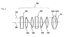
- a spherical aberration corrector disclosed in non-patent document 2 is indicated by numeral 100 and equipped in a transmission electron microscope having an objective lens 101.
- the corrector 100 is mounted ahead of the objective lens 101 (i.e., mounted in the illumination system) as shown in Fig. 5 or behind the objective lens 101 (i.e., mounted in the projection system) .
- This corrector 100 has hexapole elements 102 and 103 located on the optical axis 120, a first pair of transfer lenses 104 and 105 mounted between the hexapole elements 102 and 103, and a second pair of transfer lenses 104 and 105 mounted between the hexapole element 103 and the objective lens 101.
- the two stages of hexapole elements 102 and 103 are so arranged that they are coincident as viewed along the optical axis 120. That is, three-fold symmetric fields created respectively by the hexapole elements 102 and 103 bear no rotational relationship to each other about the optical axis 120.
- Each pair of transfer lenses 104 and 105 is made of two axisymmetric lenses. The transfer lenses 104 and 105 located between the hexapole elements 102 and 103 form, in the position of the other hexapole element 103, an image conjugate with an image formed by the hexapole element 102.
- the transfer lenses 104 and 105 located between the hexapole element 103 and the objective lens 101 form, in a coma-free plane 101a of the objective lens 101, an image conjugate with an image formed by the hexapole element 103.
- An electron beam 121 incident on the coma-free plane 101a is focused on a surface 101b of a sample.
- the two stages of hexapole elements 102 and 103 produce negative spherical aberrations in mutually perpendicular directions with respect to the electron beam 121 and, therefore, the two stages of hexapole elements 102, 103 and the first pair of transfer lenses 104 and 105 cooperate to form isotropic negative spherical aberration with respect to the optical axis 120.
- the two stages of hexapole elements 102 and 103 act as a so-called concave lens. This negative spherical aberration suppresses the positive spherical aberration in the objective lens 101 that is a so-called convex lens.
- a hexapole element produces three-fold astigmatism which is a second-order aberration. Accordingly, in the corrector 100 of non-patent document 2, the three-fold astigmatism in the hexapole element 103 cancels the three-fold astigmatism in the hexapole element 102.
- the aforementioned aberration correction technique can suppress the three-fold astigmatism but correct only up to the fourth-order aberration. This technique cannot completely correct still higher-order aberrations.
- a six-fold astigmatismthat is one fifth-order aberration appears in return for cancellation of the three-fold astigmatism produced by each three-fold symmetric field. Because this is a factor restricting the aberration correction, further improvement of spatial resolution cannot be anticipated.
- patent document 1 discloses a spherical aberration corrector capable of correcting the six-fold astigmatism.
- three stages of multipole elements for producing 3 three-fold symmetric fields are arranged about the optical axis so as to be angularly spaced from each other by a given angle, thus suppressing the six-fold astigmatism.
- Non-patent document 3 shows the results of a theoretical analysis of a spherical aberration corrector capable of correcting the six-fold astigmatism, and proposes a spherical aberration corrector having two stages of hexapole elements and pairs of transfer lenses in the same way as non-patent document 2. According to the results of the analysis, in a case where an excitation current is applied to each hexapole element to maintain constant the third-order spherical aberration, the six-fold astigmatism is minimized when the length of each hexapole element taken along its optical axis assumes a certain value.
- the spherical aberration correctors disclosed in patent document 1 and non-patent document 3 suppress six-fold astigmatism using three-fold symmetric fields.
- they are based on a design concept different from that of the conventional spherical aberration corrector using two three-fold symmetric fields such as disclosed in non-patent document 2. Therefore, these correctors are complex to adjust because there is a need to search for new set values such as excitation currents and the dimensions of the hexapole elements.
- a spherical aberration corrector which is for use in a charged particle beam instrument, is easy to design, and is capable of correcting even six-fold astigmatism. It is further desirable to provide a method of spherical aberration correction implemented by this spherical aberration corrector.
- a first aspect of the present invention provides a spherical aberration corrector which is for use in a charged particle beam instrument and which has a first pair of multipole elements for producing a first pair of three-fold symmetric fields in which three-fold astigmatisms produced mutually are canceled out, and a second pair of multipole elements located behind the first pair of multipole elements.
- the second pair of multipole elements produces a second pair of three-fold symmetric fields in which three-fold astigmatisms produced mutually are canceled out.
- Six-fold astigmatisms produced by the second pair of multipole elements are angularly spaced by 30° about an optical axis from six-fold astigmatisms produced by the first pair of multipole elements.
- An embodiment of the invention provides a spherical aberration corrector which is for use in a charged particle beam instrument and which has a first pair of multipole elements for producing a first pair of three-fold symmetric fields in which three-fold astigmatisms produced mutually are canceled out, a second pair of multipole elements located behind the first pair of multipole elements, and a rotation lens located between the first pair of multipole elements and the second pair of multipole elements.
- the second pair of multipole elements produces a second pair of three-fold symmetric fields in which three-fold astigmatisms produced mutually are canceled out.
- the rotation lens rotates a charged particle beam passed through the first pair of multipole elements such that six-fold astigmatisms produced by the second pair of multipole elements are angularly spaced by 30° about an optical axis from six-fold astigmatisms produced by the first pair of multipole elements.
- a further embodiment of the invention provides a spherical aberration corrector which is for use in a charged particle beam instrument and which has a first pair of multipole elements for producing a first pair of three-fold symmetric fields in which three-fold astigmatisms produced mutually are canceled out, a second pair of multipole elements located behind the first pair of multipole elements, and a rotating mechanism located between the first pair of multipole elements and the second pair of multipole elements.
- the second pair of multipole elements produces a second pair of three-fold symmetric fields in which three-fold astigmatisms produced mutually are canceled out.
- the rotating mechanism rotates at least one pair of the multipole elements of the first and second pairs such that six-fold astigmatisms produced by the second pair of multipole elements are angularly spaced by 30° about an optical axis from six-fold astigmatisms produced by the first pair of multipole elements.
- a spherical aberration corrector associated with any one of the first through third aspects further comprises pairs of transfer lenses mounted between successive ones of the multipole elements.
- the transfer lenses of each pair form a first image conjugate with a second image formed in one of the multipole elements adjacent to the transfer lenses of the pair such that the first image is located in the other multipole element.
- the spherical aberration corrector further comprises a pair of transfer lenses which is mounted between an objective lens and one of the multipole elements closest to the objective lens and which forms a first image conjugate with a second image formed in the multipole element closest to the objective lens such that the first image is located in a coma-free plane of the objective lens.
- each of the multipole elements is a hexapole element or a dodecapole (12-pole) element.
- each one pair of three-fold symmetric fields of the first and second pairs is preferably any one of (a) a pair of magnetostatic fields, (b) a pair of electrostatic fields, and (c) a superimposition of a pair of magnetostatic fields and a pair of electrostatic fields.
- a second aspect of the present invention provides a method of correcting spherical aberration in a charged particle beam instrument. This method starts with producing a first pair of three-fold symmetric fields in which three-fold astigmatisms produced mutually are canceled out. A second pair of three-fold symmetric fields in which three-fold astigmatisms produced mutually are canceled out is formed behind the first pair of three-fold symmetric fields. Six-fold astigmatisms produced by the second pair of three-fold symmetric fields are angularly spaced by 30° about an optical axis from six-fold astigmatisms produced by the first pair of three-fold symmetric fields.
- Another embodiment of the present invention provides a method of correcting spherical aberration in a charged particle beam instrument.
- This method starts with producing a first pair of three-fold symmetric fields in which three-fold astigmatisms produced mutually are canceled out.
- a second pair of three-fold symmetric fields in which three-fold astigmatisms produced mutually are canceled out is produced behind the first pair of three-fold symmetric fields.
- a charged particle beam passed through the first pair of multipole elements is rotated such that six-fold astigmatisms in the second pair of three-fold symmetric fields are angularly spaced by 30° about an optical axis from six-fold astigmatisms in the first pair of the three-fold symmetric fields.
- a method of correcting spherical aberration in a charged particle beam instrument in accordance with the fourth or fifth aspect further comprises the step of producing a field between any two adjacent ones of the three-fold symmetric fields to form a first image conjugate with a second image formed in one of the two three-fold symmetric fields such that the first image is located in the other three-fold symmetric field.
- the method of spherical aberration correction preferably further comprises the step of producing a field between an objective lens and one of the three-fold symmetric fields which is closest to the objective lens to form a first image conjugate with a second image formed in the three-fold symmetric field closest to the objective lens such that the first image is located in a coma-free plane of the objective lens.
- each one pair of the three-fold symmetric fields of the first and second pairs is preferably any one of (a) a pair of magnetostatic fields, (b) a pair of electrostatic fields, and (c) a superimposition of a pair of magnetostatic fields and a pair of electrostatic fields.
- Each one pair of multipole elements of the first and second pairs produces negative spherical aberrations and cancels six-fold astigmatisms produced mutually. At this time, in each pair of multipole elements, three-fold astigmatisms are also canceled out. Consequently, positive spherical aberration in the objective lens can be corrected while removing the three-fold astigmatisms and six-fold astigmatisms. Hence, the spatial resolution of the charged particle beam instrument is improved.
- the inventive spherical aberration corrector employs a configuration equivalent to two stages of spherical aberration correctors each using a pair of multipole elements, it is possible that the operation, geometry, dimensions, and so on of a spherical aberration corrector using only a single pair of multipole elements can be used as references. In consequence, the development costs can be reduced.
- the spherical aberration corrector of the present embodiment is equipped in a scanning transmission electron microscope (STEM) are described below.
- the corrector can also be equipped in a scanning electron microscope (SEM), a transmission electron microscope (TEM), a focused ion beam (FIB) system, or other charged particle beam instrument.
- SEM scanning electron microscope
- TEM transmission electron microscope
- FIB focused ion beam
- the spherical aberration correction method of the present invention can be applied to any of the above-described charged particle beam instruments, as well as to a transmission electron microscope.
- Fig. 1 is a schematic diagram of a spherical aberration corrector 10 of the present embodiment.
- the corrector 10 is mounted as an illumination-side aberration correction optical system ahead of an objective lens 11 or as a projector-side aberration correction optical system behind the objective lens 11.
- Fig. 1 shows an example in which the spherical aberration corrector 10 is mounted as the illumination-side aberration correction optical system.
- the corrector 10 has a pair of multipole elements A and B for producing a first pair of three-fold symmetric fields that are symmetrical with respect to an optical axis 20, another pair of multipole elements C and D mounted behind the pair of multipole elements A and B.
- the multipole elements C and C produce a second pair of three-fold symmetric fields that are symmetrical with respect to the optical axis 20. That is, in the present embodiment, the four stages of multipole elements A, B, C, and D are arranged in a row along the optical axis 20. Each individual multipole element produces a three-fold symmetric field.
- Each of the multipole elements A-D is a hexapole element or a dodecapole (12-pole) element producing any one of a magnetostatic field of three-fold symmetry, an electrostatic field of three-fold symmetry, and a superimposition of such a magnetostatic field and such a electrostatic field.
- each of the multipole elements A-D has a thickness of t along the optical axis 20.
- the multipole elements may be different from each other in thickness t.
- a three-fold symmetric field produced by each multipole element is referred to as a primary term of the field produced by the multipole element.
- a multipole element produces weak fields owing to higher-order terms other than the primary term.
- fields owing to higher-order terms other than the primary term are neglected for the intended purpose of the multipole element or merely are parasitic factors.
- the thickness of the multipole element is increased, the effects of higher-order terms other than the primary term manifest themselves.
- each multipole element having the thickness t along the optical axis 20 and built in accordance with the present embodiment produces fields owing to higher-order terms (other than the primary term) applicable to correction of chromatic aberration.
- the spherical aberration corrector 10 of the present embodiment preferably has a pair of transfer lenses 14 and 15 between any two adjacent ones of the multipole elements (i.e., between the multipole elements A and B, between the multipole elements B and C, and between the multipole elements C and D).
- Transfer lenses 14 and 15 of each pair form an image conjugate with an image formed in one of the two multipole elements adjacent to this pair of transfer lenses 14 and 15 such that the image is located in the other multipole element.
- the magnification of one pair of transfer lenses 14 and 15 is - 1.
- the principal plane is located at the focal point on the object side of the transfer lens 14, while the principal plane of the other multipole element B or D is located at the focal point on the image side of the transfer lens 15.
- transfer lenses 14 and 15 of a further pair are preferably mounted between the objective lens 11 and one (multipole element D in the example shown in Fig. 1 ) of the multipole elements A-D closest to the objective lens 11.
- the transfer lenses 14 and 15 of this pair form a first image conjugate with a second image formed in the multipole element D such that the first image is located in a coma-free plane 11a of the objective lens 11.
- the coma-free plane 11a is substantially identical with the front focal plane of the objective lens 11.
- An electron beam 21 incident on the coma-free plane 11a is focused onto a surface 11b of a sample.
- the multipole elements A and B produce a pair of three-fold symmetric fields, which in turn produces negative spherical aberrations in two mutually perpendicular directions that are perpendicular to the optical axis 20. Accordingly, the negative spherical aberrations reduce the positive spherical aberration of the objective lens.
- the multipole elements A and B produce three-fold astigmatisms which are opposite in sense but identical in magnitude. Therefore, the three-fold astigmatism produced by the multipole element A is canceled out by the three-fold astigmatism produced by the multipole element B.
- the pair of three-fold symmetric fields produced by the multipole elements A and B cancels the three-fold astigmatisms but induce a six-fold astigmatism that is a fifth-order aberration, which has been a problem with the conventional spherical aberration corrector.
- a 6 _ AB A 3 2 ⁇ A 3 2 14 M 6 ⁇ f 6 ⁇ t 7
- t is the thickness of each of the multipole elements A and B taken along the optical axis 20
- M is the demagnification factor of the objective lens 11 (i.e., the ratio in size of the image in the coma-free plane of the objective lens to the image in the principal plane of the multipole element A or B)
- f is the focal distance of the objective lens.
- an image created by an electron beam passed through the multipole elements A and B contains six-fold astigmatism.
- the multipole elements C and D are similar in fundamental function with the multipole elements A and B.
- the multipole elements C and D produce a pair of three-fold symmetric fields for giving rise to negative spherical aberrations in two mutually perpendicular directions that are perpendicular to the optical axis 20.
- the multipole elements C and D produce three-fold astigmatisms which are opposite in sense but identical in magnitude. Accordingly, the three-fold astigmatism in the multipole element C is canceled out by the three-fold astigmatism in the multipole element D, in the same way as for the multipole elements A and B. In return, six-fold astigmatism is produced.
- the azimuths of the three-fold astigmatisms produced by the multipole elements C and D, respectively, are angularly shifted by 30° about the optical axis 20 from the azimuths produced by the multipole elements A and B.
- Their magnitudes are equal to the magnitudes of the astigmatisms produced by the multipole elements A and B. That is, the six-fold astigmatisms produced by the multipole elements A and B are angularly spaced by 30° about the optical axis 20 from the six-fold astigmatisms produced by the multipole elements C and D.
- the six-fold astigmatisms produced by the multipole elements A and B are canceled out by the six-fold astigmatisms produced by the multipole elements C and D because of this angularly spaced relationship.
- a 6_ Total A 6 _ AB + A 6 _ CD
- a 6 _ Total t 7 14 M 6 ⁇ f 6 ⁇ A 3 2 a 3 2 ⁇ exp 6 ⁇ i ⁇ a ⁇ 3 + exp 6 ⁇ i ⁇ a ⁇ 3
- a 6 _ Total ⁇ exp 0 + exp i ⁇ 0
- Fig. 2 Examples of the angularly spaced relationship between the above-described three-fold astigmatisms and six-fold astigmatisms are shown in Fig. 2 .
- Triangles T A , T B , T C , and T D schematically represent the magnitudes of three-fold astigmatisms produced by the multipole elements A, B, C, and D, respectively, within a plane perpendicular to the optical axis 20.
- hexagons H AB and H CD schematically represent the magnitudes of six-fold astigmatisms produced by the pair of multipole elements A and B and the pair of multipole elements C and D within the plane perpendicular to the optical axis 20.
- the three-fold astigmatism in the multipole element A produces the strongest effect in three directions (including the + Y-axis direction) that are angularly spaced from each other by 120° as indicated by the triangle T A in Fig. 2 .
- the multipole element B produces three-fold astigmatism that is identical in magnitude but opposite in sense to the three-fold astigmatism produced by the multipole element A.
- the triangle T B representing the astigmatism is angularly spaced by 60° from the triangle T A or obtained by folding the triangle T A back along the X-axis.
- the resultant three-fold astigmatism is 0.
- six-fold astigmatism indicated by the hexagon H AB shown in Fig. 2 appears.
- the angularly spaced relationship between the triangles T C and T D is similar to the angularly spaced relationship between the triangles T A and T B . Because the multipole element D produces three-fold astigmatism that is opposite in sense but identical in magnitude to the three-fold astigmatism produced by the multipole element C, the triangle T D is obtained by rotating the triangle T C through 60°. However, the triangle T D can be said to have been folded back along the Y-axis because the difference in azimuthal angles ⁇ a3 and ⁇ a3 between the three-fold astigmatisms produced by the multipole elements A and C is set to 30° and thus the triangle T C has been rotated through 30° relative to the triangle T A . The resultant three-fold astigmatism is 0.
- the six-fold astigmatisms produced by the pair of multipole elements A and B are angularly shifted by 30° about the optical axis from the six-fold astigmatism produced by the pair of multipole elements C and D. Therefore, as given by Eq. (7), the sum of the six-fold astigmatisms is null. At this time, in each pair of multipole elements, the three-fold astigmatisms are also canceled out.
- the positive spherical aberration in the objective lens can be corrected while removing the three-fold astigmatisms and six-fold astigmatisms, the maximum incidence angle of the electron beam allowed as a probe beam can be enlarged and the diffraction aberration can be reduced in a case where the spherical aberration corrector 10 of the present embodiment is mounted, for example, on the illumination side of an STEM. Consequently, the spatial resolution of the STEM or other charged particle beam instrument can be improved.
- the spherical aberration corrector 10 of the present embodiment is configured using two pairs of multipole elements. Spherical aberration correctors using only a single pair of multipole elements are widely known. When the spherical aberration corrector 10 of the present embodiment is designed, the operations, geometries, dimensions, and so on of the known correctors can be used as references. As a consequence, the development costs can be curtailed.
- the multipole element A may produce three-fold astigmatism as indicated by the triangle T B .
- the multipole element B may produce three-fold astigmatism as indicated by the triangle T A .
- the same principle applies to the multipole elements C and D.
- the three-fold astigmatisms produced by the multipole elements A and B and the three-fold astigmatisms produced by the multipole elements C and D may be interchanged.
- each of the multipole elements A, B, C, and D of the present embodiment is a hexapole element or a dodecapole element.
- the poles P of one pair of hexapole elements A' and B' are angularly spaced by 30° about the optical axis 20 from the poles Q of one pair of hexapole elements C' and D' as shown in Fig. 3 (a) in order to obtain an angular spacing of 30° between the six-fold astigmatisms.
- the poles P of one pair of hexapole elements A' and B' may be arranged to agree with the poles Q of one pair of hexapole elements C' and D' as viewed along the optical axis 20 as shown in Fig. 3(b) .
- a rotation lens 16 for rotating an electron beam 21 (image formed by the hexapole element B') passed through the hexapole element B' through 30° about the optical axis 20 is mounted between the hexapole elements B' and C' as shown in Fig. 4 .
- dodecapole elements A”, B", C", and D are used as the multipole elements A, B, C, and D, respectively. It is desired that the dodecapole elements A", B", C", and D" be so arranged that their poles are coincident as viewed along the optical axis 20. Therefore, in principle, the above-described angular spacing of 30° is obtained by controlling the polarities of the poles. However, error may be introduced in the angular spacing due to insufficient assembly accuracy. If the rotation lens 16 is mounted, it is possible to compensate for the error.
- the spherical aberration corrector 10 of the present embodiment may have a rotation mechanism (not shown) for rotating at least one pair of the multipole elements A and B and the multipole elements C and D.
- a rotation mechanism for rotating at least one pair of the multipole elements A and B and the multipole elements C and D.
- the above-described angular spacing of 30° is obtained by rotating support members (not shown) holding the multipole elements C and D around the optical axis 20 by means of the rotation mechanism.
- a strict positional relationship required between the poles when the pair of multipole elements A and B and the pair of multipole elements C and D are mounted is mitigated and, therefore, the machining costs can be suppressed.
Landscapes
- Chemical & Material Sciences (AREA)
- Analytical Chemistry (AREA)
- Electron Beam Exposure (AREA)
Applications Claiming Priority (1)
| Application Number | Priority Date | Filing Date | Title |
|---|---|---|---|
| JP2010114373A JP5502595B2 (ja) | 2010-05-18 | 2010-05-18 | 球面収差補正装置および球面収差補正方法 |
Publications (2)
| Publication Number | Publication Date |
|---|---|
| EP2388795A2 true EP2388795A2 (fr) | 2011-11-23 |
| EP2388795A3 EP2388795A3 (fr) | 2013-01-16 |
Family
ID=44117818
Family Applications (1)
| Application Number | Title | Priority Date | Filing Date |
|---|---|---|---|
| EP11166606A Withdrawn EP2388795A3 (fr) | 2010-05-18 | 2011-05-18 | Correcteur d'aberrations sphériques et procédé pour la correction d'aberrations sphériques |
Country Status (3)
| Country | Link |
|---|---|
| US (1) | US8389951B2 (fr) |
| EP (1) | EP2388795A3 (fr) |
| JP (1) | JP5502595B2 (fr) |
Families Citing this family (7)
| Publication number | Priority date | Publication date | Assignee | Title |
|---|---|---|---|---|
| JP5934517B2 (ja) * | 2012-02-24 | 2016-06-15 | 日本電子株式会社 | 色収差補正装置及び色収差補正装置の制御方法 |
| US9275817B2 (en) | 2012-04-09 | 2016-03-01 | Frederick Wight Martin | Particle-beam column corrected for both chromatic and spherical aberration |
| JP6002470B2 (ja) * | 2012-06-28 | 2016-10-05 | 株式会社日立ハイテクノロジーズ | 荷電粒子線装置 |
| JP6009981B2 (ja) * | 2013-03-28 | 2016-10-19 | 日本電子株式会社 | 荷電粒子ビーム偏向装置 |
| EP3333877A1 (fr) | 2016-12-07 | 2018-06-13 | JEOL Ltd. | Tube-chemise et microscope électronique |
| US9997327B1 (en) | 2016-12-08 | 2018-06-12 | Jeol Ltd. | Liner tube and electron microscope |
| JP6843794B2 (ja) * | 2018-03-30 | 2021-03-17 | 日本電子株式会社 | 収差補正装置および荷電粒子線装置 |
Citations (2)
| Publication number | Priority date | Publication date | Assignee | Title |
|---|---|---|---|---|
| US20080265172A1 (en) * | 2005-10-24 | 2008-10-30 | Stephan Uhlemann | Electron-Optical Corrector for an Aplanatic Imaging System |
| JP2009054565A (ja) | 2007-08-02 | 2009-03-12 | Jeol Ltd | 収差補正装置 |
Family Cites Families (9)
| Publication number | Priority date | Publication date | Assignee | Title |
|---|---|---|---|---|
| JP2002042707A (ja) * | 2000-07-25 | 2002-02-08 | Jeol Ltd | 非点収差補正装置 |
| JP3896150B2 (ja) * | 2001-07-13 | 2007-03-22 | 日本電子株式会社 | 電子顕微鏡の球面収差補正装置 |
| US6770887B2 (en) * | 2002-07-08 | 2004-08-03 | Ondrej L. Krivanek | Aberration-corrected charged-particle optical apparatus |
| US7015481B2 (en) * | 2003-02-14 | 2006-03-21 | Jeol Ltd. | Charged-particle optical system |
| JP4988216B2 (ja) * | 2006-02-03 | 2012-08-01 | 株式会社日立ハイテクノロジーズ | 収差補正装置を搭載した荷電粒子線装置 |
| DE102006017686A1 (de) * | 2006-04-15 | 2007-10-18 | Ceos Corrected Electron Optical Systems Gmbh | Elektronenoptischer Korrektor für aplanatische Abbildungssysteme |
| JP4533444B2 (ja) * | 2008-03-31 | 2010-09-01 | 株式会社日立製作所 | 透過型電子顕微鏡用収差補正器 |
| JP5237734B2 (ja) * | 2008-09-24 | 2013-07-17 | 日本電子株式会社 | 収差補正装置および該収差補正装置を備える荷電粒子線装置 |
| JP5623719B2 (ja) * | 2008-10-06 | 2014-11-12 | 日本電子株式会社 | 荷電粒子線装置の色収差補正装置及びその補正方法 |
-
2010
- 2010-05-18 JP JP2010114373A patent/JP5502595B2/ja active Active
-
2011
- 2011-05-16 US US13/108,207 patent/US8389951B2/en active Active
- 2011-05-18 EP EP11166606A patent/EP2388795A3/fr not_active Withdrawn
Patent Citations (2)
| Publication number | Priority date | Publication date | Assignee | Title |
|---|---|---|---|---|
| US20080265172A1 (en) * | 2005-10-24 | 2008-10-30 | Stephan Uhlemann | Electron-Optical Corrector for an Aplanatic Imaging System |
| JP2009054565A (ja) | 2007-08-02 | 2009-03-12 | Jeol Ltd | 収差補正装置 |
Non-Patent Citations (3)
| Title |
|---|
| A.V. CREWE, D. KOPF, OPTIK, vol. 55, 1980, pages 1 - 10 |
| H. MULLER ET AL., MICROSC., MICROANAL., vol. 12, 2006, pages 442 - 455 |
| H. ROSE, OPTIK, vol. 85, 1990, pages 19 - 24 |
Also Published As
| Publication number | Publication date |
|---|---|
| EP2388795A3 (fr) | 2013-01-16 |
| JP5502595B2 (ja) | 2014-05-28 |
| US20110284758A1 (en) | 2011-11-24 |
| JP2011243409A (ja) | 2011-12-01 |
| US8389951B2 (en) | 2013-03-05 |
Similar Documents
| Publication | Publication Date | Title |
|---|---|---|
| EP2020673B1 (fr) | Système de correction d'aberrations | |
| US8178850B2 (en) | Chromatic aberration corrector for charged-particle beam system and correction method therefor | |
| EP2325863B1 (fr) | Correcteur pour aberrations axiales d'une lentille pour particules chargées | |
| US8389951B2 (en) | Spherical aberration corrector and method of spherical aberration correction | |
| US9793088B2 (en) | Two-stage dodecapole aberration corrector for charged-particle beam | |
| EP1381073B1 (fr) | Appareil optique pour particules chargées ayant une correction d'aberration | |
| JP6278553B2 (ja) | 2次電子光学系及び検出デバイス | |
| EP2453463B1 (fr) | Procédé pour l'alignement axial d'un faisceau de particules chargées et système de faisceaux de particules chargées | |
| US8785880B2 (en) | Chromatic aberration corrector and electron microscope | |
| US11081313B2 (en) | Particle-optical corrector which is free from axial aberrations of sixth order and electron microscope with corrector | |
| EP1914785B1 (fr) | Correcteur d'aberrations et procédé pour la correction d'aberrations | |
| EP3547348B1 (fr) | Correcteur d'aberrations et dispositif à faisceau de particules chargées | |
| US8884245B2 (en) | Corrector for the correction of chromatic aberrations in a particle-optical apparatus | |
| EP2600382A1 (fr) | Dispositif de correction d'aberration et dispositif à faisceau de particules chargées l'employant | |
| US20120074315A1 (en) | High resolution energy-selecting electron beam apparatus | |
| JP7200062B2 (ja) | 荷電粒子ビーム装置 | |
| US6555818B1 (en) | Transmission electron microscope | |
| JP4343951B2 (ja) | 荷電粒子ビーム系用の単段式荷電粒子ビームエネルギー幅低減系 | |
| JP2003502802A (ja) | 粒子レンズの色収差を除去する静電修正器 | |
| US12394587B2 (en) | Simple spherical aberration corrector for SEM | |
| US12362132B2 (en) | Simple spherical aberration corrector for SEM | |
| JP5666227B2 (ja) | 色収差補正ビーム偏向器、色収差補正ビーム分離器、荷電粒子デバイス、色収差補正ビーム偏向器を動作させる方法、及び色収差補正ビーム分離器を動作させる方法 | |
| JP2007242490A (ja) | 荷電粒子線光学系用の収差補正光学装置及び光学系 |
Legal Events
| Date | Code | Title | Description |
|---|---|---|---|
| AK | Designated contracting states |
Kind code of ref document: A2 Designated state(s): AL AT BE BG CH CY CZ DE DK EE ES FI FR GB GR HR HU IE IS IT LI LT LU LV MC MK MT NL NO PL PT RO RS SE SI SK SM TR |
|
| AX | Request for extension of the european patent |
Extension state: BA ME |
|
| PUAI | Public reference made under article 153(3) epc to a published international application that has entered the european phase |
Free format text: ORIGINAL CODE: 0009012 |
|
| PUAL | Search report despatched |
Free format text: ORIGINAL CODE: 0009013 |
|
| AK | Designated contracting states |
Kind code of ref document: A3 Designated state(s): AL AT BE BG CH CY CZ DE DK EE ES FI FR GB GR HR HU IE IS IT LI LT LU LV MC MK MT NL NO PL PT RO RS SE SI SK SM TR |
|
| AX | Request for extension of the european patent |
Extension state: BA ME |
|
| RIC1 | Information provided on ipc code assigned before grant |
Ipc: H01J 37/153 20060101AFI20121212BHEP |
|
| 17P | Request for examination filed |
Effective date: 20130716 |
|
| RBV | Designated contracting states (corrected) |
Designated state(s): AL AT BE BG CH CY CZ DE DK EE ES FI FR GB GR HR HU IE IS IT LI LT LU LV MC MK MT NL NO PL PT RO RS SE SI SK SM TR |
|
| 17Q | First examination report despatched |
Effective date: 20141020 |
|
| STAA | Information on the status of an ep patent application or granted ep patent |
Free format text: STATUS: THE APPLICATION IS DEEMED TO BE WITHDRAWN |
|
| 18D | Application deemed to be withdrawn |
Effective date: 20150501 |