EP2389006A2 - System und Verfahren zur Bildverarbeitung - Google Patents
System und Verfahren zur Bildverarbeitung Download PDFInfo
- Publication number
- EP2389006A2 EP2389006A2 EP11164076A EP11164076A EP2389006A2 EP 2389006 A2 EP2389006 A2 EP 2389006A2 EP 11164076 A EP11164076 A EP 11164076A EP 11164076 A EP11164076 A EP 11164076A EP 2389006 A2 EP2389006 A2 EP 2389006A2
- Authority
- EP
- European Patent Office
- Prior art keywords
- image
- interpolated
- images
- matrix
- camera positions
- Prior art date
- Legal status (The legal status is an assumption and is not a legal conclusion. Google has not performed a legal analysis and makes no representation as to the accuracy of the status listed.)
- Withdrawn
Links
Images




Classifications
-
- H—ELECTRICITY
- H04—ELECTRIC COMMUNICATION TECHNIQUE
- H04N—PICTORIAL COMMUNICATION, e.g. TELEVISION
- H04N13/00—Stereoscopic video systems; Multi-view video systems; Details thereof
- H04N13/20—Image signal generators
- H04N13/282—Image signal generators for generating image signals corresponding to three or more geometrical viewpoints, e.g. multi-view systems
-
- G—PHYSICS
- G06—COMPUTING OR CALCULATING; COUNTING
- G06T—IMAGE DATA PROCESSING OR GENERATION, IN GENERAL
- G06T15/00—Three-dimensional [3D] image rendering
- G06T15/10—Geometric effects
- G06T15/20—Perspective computation
- G06T15/205—Image-based rendering
-
- G—PHYSICS
- G06—COMPUTING OR CALCULATING; COUNTING
- G06T—IMAGE DATA PROCESSING OR GENERATION, IN GENERAL
- G06T7/00—Image analysis
- G06T7/30—Determination of transform parameters for the alignment of images, i.e. image registration
- G06T7/33—Determination of transform parameters for the alignment of images, i.e. image registration using feature-based methods
-
- G—PHYSICS
- G06—COMPUTING OR CALCULATING; COUNTING
- G06T—IMAGE DATA PROCESSING OR GENERATION, IN GENERAL
- G06T7/00—Image analysis
- G06T7/97—Determining parameters from multiple pictures
-
- H—ELECTRICITY
- H04—ELECTRIC COMMUNICATION TECHNIQUE
- H04N—PICTORIAL COMMUNICATION, e.g. TELEVISION
- H04N13/00—Stereoscopic video systems; Multi-view video systems; Details thereof
- H04N13/10—Processing, recording or transmission of stereoscopic or multi-view image signals
- H04N13/106—Processing image signals
- H04N13/111—Transformation of image signals corresponding to virtual viewpoints, e.g. spatial image interpolation
-
- G—PHYSICS
- G06—COMPUTING OR CALCULATING; COUNTING
- G06T—IMAGE DATA PROCESSING OR GENERATION, IN GENERAL
- G06T2207/00—Indexing scheme for image analysis or image enhancement
- G06T2207/10—Image acquisition modality
- G06T2207/10004—Still image; Photographic image
- G06T2207/10012—Stereo images
-
- G—PHYSICS
- G06—COMPUTING OR CALCULATING; COUNTING
- G06T—IMAGE DATA PROCESSING OR GENERATION, IN GENERAL
- G06T2207/00—Indexing scheme for image analysis or image enhancement
- G06T2207/20—Special algorithmic details
- G06T2207/20228—Disparity calculation for image-based rendering
Definitions
- the invention relates to a system and method of image processing.
- the display of 3D imagery can be created from a number of views of a camera subject taken from different angles. Often the captured images are from a limited number of camera positions so it may be necessary to interpolate between the capture images to give the impression of true 3D across the range of viewing angles.
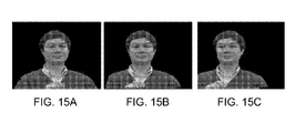
- FIG. 15(a), 15(b) and 15(c) of the accompanying drawings show the interpolated results of such a camera setup.
- Figure 15(a) is the view taken from a right webcam and
- Figure 15(c) is the view taken from a left webcam.
- Figure 15(b) is the interpolated view.
- a rectification process is required to make use of the epi-polar constraint in the stereo matching process.
- the rectification can be done based on a one-time calibration when the positions of the cameras' position are fixed, or with some image processing method (e.g. feature point detection and matching) when calibration is not feasible such as described in R. I. Hartley "Theory and Practice of Projective Rectification”. Int. Journal of Computer Vision 35: 115-127. 1999.
- the purpose of rectification is to transform the two input images onto a common image plane where the matching is constraint within the same line between two input images as illustrated in Figure 14 of the accompanying drawings.
- View interpolation can also be applied to the output from a camera array with more than two cameras to cover larger viewing zones.
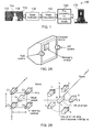
- Figure 2b shows two examples of camera arrays with more than two cameras. In these two setups, all the cameras are parallel and the image planes can be considered to coincide with each other. Thus post processing may not be necessary. If however the image planes of all the cameras do not coincide, then post processing may become necessary.
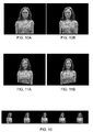
- Figure 10 shows the abrupt change between one image to the next at the boundary.
- this discontinuity effect in the interpolated results may cause unnatural abrupt changes when the viewer is moving around the display.
- Another unnatural effect of the interpolated results may be the incorrect keystone when viewed around the RayModeller image display system 170 that is illustrated in Figure 1 . Again, this is caused by the fact that all the interpolated view images are on the same rectified image plane and the keystone is incorrect for different viewing angles.
- Transformations between the original images and the rectified images for the extreme views are known from the image-rectification process.
- the transformation for the interpolation results between these transformations is not available.
- interpolation between the two transformations for the two extreme views might be done in order to obtain a visually sensible motion.
- Simple interpolation of the transformation matrices H( i ) b , H( i+1 ) a may lead to unnatural or even invalid transformations (mapping part of the image to infinity).
- the motion of the four corners of the rectified images may be used as references. The positions of these four corners are linearly interpolated and the intermediate transformation is determined as the transformation that maps these four corners to the screen corners.
- this alternative method can generate visually continuous results, it may not be accurate and it may be complex.
- the assumption of linear movement of four corners may be invalid generally and the error may become visible when the change in viewing position and direction between the two cameras is big.
- the algorithm may be complex as user input of scene corners is needed and additional estimation step based on the four corner positions is needed.
- the invention in general terms in a first aspect relates to "un-rectification" of the interpolated results to bring them to different image planes according to the viewing angle. This may have the advantage that image planes of intermediate results transit smoothly according to the viewing angle, which may create a more natural and physically valid viewing effect.
- interpolated images from multiple camera pairs can be seamed together without the discontinuity problem. Correct keystone and size compensation may be achieved at the same time for the intermediate results.
- One or more embodiments may permit image interpolation to be used for the creation of special effects such as the "bullet time" effect used in the Matrix movie. Fewer cameras may be needed when creating a special effect, or when creating a 3D view, and a more flexible viewing effect may also be created.
- One or more embodiments may involve simple matrix calculation and may be implemented using a personal computer, an embedded device or consumer electronics product.
- One or more embodiments may be used for generating data such as images, 3D models or image textures for various 3D display platforms.
- the invention relates to baseline adjustment. This may have the advantage that for linear camera setups, post processing can be much simplified.
- the image acquisition system 110 comprises a plurality of cameras 112, 114, 116 which are positioned at a plurality of different camera positions or views.
- the image acquisition system 110 acquires a plurality of images from the plurality of cameras 112, 114, 116.
- the plurality of images is then provided to image interpolation the image processing system 150.
- the image acquisition system 110 can take the form of a circular setup as illustrated in Figure 1 .
- the image acquisition system 110 can take the form of hardware for a teleconference system as illustrated in Figure 2a .
- the image acquisition system 110 can also take the form of camera arrays with more than two cameras such as those illustrated in Figure 2b .
- the image acquisition system 110 alternatively can take the form of a linear, inward looking straight track setup as illustrated in Figure 2c and which can be used for ray reconstruction for a 3D display.
- the image acquisition system 110 can take the form of a camera array as illustrated in Figure 2d which is used in movie productions e.g. in the production of The Matrix.
- the image acquisition system 110 can instead comprise a single camera taking a plurality of images from a plurality of different camera positions or views.
- the cameras used may be handheld cameras, mounted cameras, portable video cameras, mobile phone cameras, web-cameras or surveillance cameras.
- the cameras used can also be either progressive scanning or interlace scanning.
- the image rectification system 130 receives as an input the plurality of images from the image acquisition system 110.
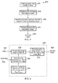
- the image rectification system 130, image interpolation system 140 and image processing system 150 carry out a method 400 of image processing as shown in Figure 4 , which will be described to a greater detail later.
- the result of the image post processing system 150 is a plurality of "un-rectified" images.
- the image processing system 150 can be implemented as a piece of software on a single personal computer, or realized in an embedded hardware form as an FPGA (Field Programmable Gates Array), or be implemented across multiple computers and/or embedded devices, or it could be implemented using a System-on-chip (SOC) solution.
- FPGA Field Programmable Gates Array
- SOC System-on-chip
- it may be implemented within a video camera used to capture the images or in a display or player used to display the images
- the image display system 170 then displays the plurality of "un-rectified” images produced by the image processing system 150.
- the image display system 170 can take the form of a 3D display such as the Sony® RayModellerTM developed by Sony and released at the Digital Contents Expo 2009, which is illustrated in Figure 1 .
- the RayModeller has a cylindrical concept design that can be viewed from all angles, thus providing 360-degree viewing.
- the RayModeller is about 10.6-inches tall and about 5.1-inches in diameter, and glasses are not needed to view the 3D effect.
- the image display system 170 can also be a computer monitor, a television or a projector.
- the method 400 includes the algorithm implemented in the image rectification system 130, image interpolation system 140 and image processing system 150 to process the images.
- a plurality of images are obtained from the plurality of camera positions or views.
- This plurality of images may be obtained from an image acquisition system 110 such as that illustrated in Figure 1 .
- Rectification is performed between pairs of images from adjacent views. Rectification permits the use of the epi-polar constraint in the stereo matching process. The purpose of rectification is thus to transform the pair of images onto a common image plane, as is illustrated in Figure 14 .
- H ( i )a is the rectification matrix for the i-th camera in the pair made of (i-1)-th and i-th cameras
- H ( i )b is the rectification matrix for the i-th camera in the pair made of i-th and (i+1)-th cameras.
- H ( i ) ⁇ H ( i )b is the rectification matrix for the i-th camera in the pair made of i-th and (i+1)-th cameras.
- the images before rectification 1410 have different image planes and the images resulting from rectification 1420 have a common image plane. Matching is constrained within the same line 1422 across both images.
- the rectification 430 can be performed using any method of image rectification that is known in the art.
- the rectification can be done based using information obtained in a one-time calibration if the camera positions are fixed, or with some image processing method (e.g. using feature point detection and matching) when calibration is not feasible.
- View interpolation 440 is then performed on the pairs of images after the images are rectified. This can be done using any interpolation method that is known in the art.
- the interpolation can be done using dynamic programming matching such as that done in Yuyu Liu, Yamaoka, K., Sato, H., Nakamura, A., Iwai, Y., Ooi, K., Weiguo Wu, and Yoshigahara, T.. Eye-contact visual communication with virtual view synthesis. Proceedings of IEEE Consumer Communications and Networking Conference, 2005 (CCNC 2005). Page: 235- 240 ).
- Figure 7 shows the interpolated images 710a to 710e from view interpolation 440 of the camera position pair P 1 consisting of camera positions 740 and 742. Also, the interpolated images 715a to 715e are from view interpolation 440 of the camera position pair P 2 consisting of camera positions 742 and 744. It can be seen that the interpolated images 710a to 710e are on a different plane from the interpolated images 715a to 715e i.e. the planes 730 and 732 respectively.
- post-processing is then performed on the interpolated images.
- the post-processing step is illustrated to a greater detail in Figure 5 and produces a plurality of "un-rectified" images.
- the corrected images resulting from post-processing are then available for display using an image display system 170 such as that illustrated in Figure 1 .
- Post-processing 450 of the interpolated images in the post processing system 150 will be described with the aid of Figure 5 .
- Post-processing 450 results in "un-rectification" of each interpolated image N onto an image plane corresponding to the viewing angle.
- the viewing angle for an interpolated image N is the angular position about a camera subject 750 of a virtual camera position corresponding to the interpolated image N.
- the viewing angle can be indicated by ⁇ i.e.
- N is an index of the interpolated images resulting from a pair of camera positions. Assuming that there are a total of M images in the set of interpolated images from the i and ( i +1 ) camera positions, then the post-processing 450 may be applied to each interpolated images N in the set consisting of 1 ⁇ N ⁇ M.
- the interpolated image N 502 is provided.
- the rectification data for the i and i camera positions are obtained as H ( i )b and H ( i +1)a respectively.
- the parameters 506 for the interpolated image 502 are then provided. These parameters 506 include those relating to the N view position e.g. the value of N.
- the transformation matrix H N for the interpolated image N is generated from H ( i )b , H ( i +1)a and the parameters 506. The details of the generation step 550 will be described later with the aid of Figure 6 .
- the transformation matrix H N that is generated is then applied to the interpolated image 502.
- the interpolated image 502 with H N applied may then be subjected to other image processing steps such as cropping or re-sampling. Cropping and re-sampling are optional. There are two reasons why these steps processing may be needed: 1) different camera have different field of view, thus it's better to crop the image so the result only contains the common area visible to all cameras; 2) further cropping or re-sampling may be needed to fit the images size to the display.
- the camera resolution may be 800x600, but the display resolution may be only 128x128.
- the first and final “un-rectified” images (i.e. 720e and 725a) of the two adjacent groups of "un-rectified” images 720a to 720e and 725a to 725e will have image planes identical to the image plane for the camera position 742 that is the boundary of two image groups and has the correct keystone and size factor as it's obtained from a real camera.
- the viewing of the transition between the "un-rectified” interpolation images from adjacent pairs such as e.g. P 1 and P 2 will be smooth as the image planes of the "un-rectified” images will have a smooth viewing angle transition, thus creating a natural and physically valid viewing effect.
- the generation 550 of the transformation matrix H N will be described with the aid of Figures 6 .
- the parameters 506 for the interpolated image 502 are first provided. Also, the rectification data 620 for the i and ( i +1) camera positions are obtained as H ( i )b and H ( i +1)a respectively in 504. Let H ( i )b be H L and H (i+1)a be H R . It is noted that H L and H R respectively are thus "rectification" matrices associated with the i and ( i +1) camera positions and can be obtained from the camera calibration data.
- the keystone compensation matrix K N is found using the chosen equation by interpolating between either of H L - 1 (if the chosen equation is Equation 2) or H R - 1 (if the chosen equation is Equation 1), and an identity matrix I .
- H L - 1 if the chosen equation is Equation 2
- H R - 1 if the chosen equation is Equation 1
- I an identity matrix I .
- the transformation matrices for images 810 and 820 at the ends of the series of M interpolated images are just the inverse of the "rectification" matrices for the two cameras (i.e. H L and H R ) and no transformation (i.e. the transformation matrix is an identity transformation matrix) is needed for the result at the center for keystone compensation (however, size compensation of the camera subject in the image for the change of viewing distance may still be needed as illustrated in Figure 7 ).
- the distance from the image plane to the object has been changed. Thus the image size of the same object needs to be changed. Otherwise, the object will seems to be changing its size when viewed from different angles on the 3D display. This is based on the assumption that the two camera image planes are symmetric with regard to the rectified image plane. This assumption is reasonable for most case of setups where the object of interest is kept at the center of all camera images and has been verified experimentally.
- Equation 1 and Equation 2 always generates continuous, feasible transformations. This is as opposed to the case in some prior art where interpolation is carried out between H L and H R .
- the scaling factor so for the centre interpolated image 830 is calculated.
- the scaling factor so is used to compensate for differences in the sizes of the camera subject 750 across the series of M interpolated images.
- d the viewing distance
- R is a line extending from an edge of the centre interpolated image 830 to the object of interest and ⁇ is an angle indicating the field of view of the centre interpolated image.
- the value of s 0 can be estimated in a trial-and-error method.
- T x0 and T y0 respectively are the translation of image origin horizontally and vertically in number of pixels.
- the size factor denoted by s compensates the changes in viewing distance along the position on the "rectification plane" with regard to the viewing object as illustrated in Figure 9 .
- Translation of the image origins using T x and T y keeps the viewing object at the centre of the resultant images after undergoing the "un-rectification" process.
- the transformation matrix H N can then be applied to the interpolated image N 502.
- Figure 11 shows the results after the "un-rectification" matrix H had been applied to the results shown in Figure 10 . It can be seen that the commonly visible image areas are now geometrically identical without any distortion. This simple matrix interpolation method also works well for the intermediate results as shown in Figure 16 to generate smooth and physically valid viewing effects as verified on RayModeller display.
- the same post processing can also be applied to the interpolation between free-hand shot images on static objects using a single consumer camera from a plurality of camera positions.
- One example is the interpolation among the eight images captured with a consumer camera without tripod as shown in Figure 12 .
- interpolation can be done among the plurality of captured images (in this example, 8 images) from different views.
- Post processing is done to construct a continuous view across all the images.
- the method of post-processing is capable of coping with the "big-small" effect (as shown between the first 1202 and second 1204, or the second 1204 and third 1206 captured views where the sizes of the camera subject are different) caused by different zoom setting/capturing distance.
- Interpolated views with the post processing result between the second and third input images are shown in Figure 13 .
- RayModeller it can be verified that the keystone and size factors are correctly compensate for all interpolated images.
- a “baseline adjustment” can be performed after view interpolation during post-processing.
- This embodiment may be used with linear camera setups such as that shown in Figure 2c where the camera image planes for the camera pairs are not so different from each other.
- the camera positions do not have to be aligned linearly and can for example be aligned in a curve or zig-zag, as long as the camera image planes for the camera pairs do not differ greatly from each other.
- this "baseline adjustment" method may generate negligible geometric distortions.
- the basic idea is to transform all the "rectification" image planes for each pair of cameras on to a single common plane associated with a designated pair of camera positions e.g. the rectified image plane of the center camera position pair.
- the common plane will have an axis that is substantially parallel to the linear camera positions.
- the “baseline adjustment” method is described next with reference to Figure 3 .
- “baseline adjustment” a transformation matrix is applied to all interpolated views except for those from the designated pair, e.g. the center pair consisting of the camera positions 304 and 306.
- the images from these cameras undergo a transformation that puts the images onto the same image plane as that of the "rectification plane” for camera positions 304 & 306.
- the transformation matrix is calculated as H 2 ⁇ a - 1 ⁇ H 2 ⁇ b and for those between camera positions 306 & 308, the transformation matrix is calculated as H 3 ⁇ b - 1 ⁇ H 3 ⁇ a .
- the transformation matrix can be calculated in a concatenating manner. Taking a camera position pair consisting of the i -1 and i camera positions and where the designated pair consists of the i 0 -1 and i 0 camera positions, if i ⁇ i 0 i.e. the pair is to the left of the designated camera pair, the transformation matrix is H i ⁇ a - 1 ⁇ H i ⁇ b . If however i > i 0 i.e. the pair is to the right of the designated camera pair, then the transformation matrix is H i ⁇ b - 1 ⁇ H i ⁇ a .
- proposed method may be used for different applications and the described embodiments should not be construed as limitative. For example, they can be used for the processing of medical images (such as CAT scans or ultrasound images), or images generated by radar or sonar. It is also envisaged that the proposed method may be used for the purpose of robotic vision.
Landscapes
- Engineering & Computer Science (AREA)
- Physics & Mathematics (AREA)
- Theoretical Computer Science (AREA)
- General Physics & Mathematics (AREA)
- Multimedia (AREA)
- Signal Processing (AREA)
- Computer Vision & Pattern Recognition (AREA)
- Geometry (AREA)
- Computer Graphics (AREA)
- Computing Systems (AREA)
- Image Processing (AREA)
- Closed-Circuit Television Systems (AREA)
- Two-Way Televisions, Distribution Of Moving Picture Or The Like (AREA)
Applications Claiming Priority (1)
| Application Number | Priority Date | Filing Date | Title |
|---|---|---|---|
| SG2010035665A SG176327A1 (en) | 2010-05-20 | 2010-05-20 | A system and method of image processing |
Publications (2)
| Publication Number | Publication Date |
|---|---|
| EP2389006A2 true EP2389006A2 (de) | 2011-11-23 |
| EP2389006A3 EP2389006A3 (de) | 2012-03-07 |
Family
ID=44582046
Family Applications (1)
| Application Number | Title | Priority Date | Filing Date |
|---|---|---|---|
| EP11164076A Withdrawn EP2389006A3 (de) | 2010-05-20 | 2011-04-28 | System und Verfahren zur Bildverarbeitung |
Country Status (5)
| Country | Link |
|---|---|
| US (1) | US8849013B2 (de) |
| EP (1) | EP2389006A3 (de) |
| JP (1) | JP2011243205A (de) |
| CN (1) | CN102254299A (de) |
| SG (1) | SG176327A1 (de) |
Cited By (4)
| Publication number | Priority date | Publication date | Assignee | Title |
|---|---|---|---|---|
| EP2677499A1 (de) * | 2012-06-21 | 2013-12-25 | Nokia Corporation | Verfahren, Vorrichtung und Computerprogrammprodukt zur Verarbeitung von Multimediainhalt |
| EP3321881A1 (de) * | 2016-11-14 | 2018-05-16 | Ricoh Company Ltd. | Neuartige ansichtssynthese mit tiefen neuralen konvolutionsnetzen |
| US11037364B2 (en) * | 2016-10-11 | 2021-06-15 | Canon Kabushiki Kaisha | Image processing system for generating a virtual viewpoint image, method of controlling image processing system, and storage medium |
| CN115908586A (zh) * | 2023-01-05 | 2023-04-04 | 中国人民解放军军事科学院国防科技创新研究院 | 时空标定方法、装置和存储介质 |
Families Citing this family (49)
| Publication number | Priority date | Publication date | Assignee | Title |
|---|---|---|---|---|
| US8866920B2 (en) | 2008-05-20 | 2014-10-21 | Pelican Imaging Corporation | Capturing and processing of images using monolithic camera array with heterogeneous imagers |
| EP3328048B1 (de) | 2008-05-20 | 2021-04-21 | FotoNation Limited | Aufnahme und verarbeitung von bildern mittels monolithischer kamera anordnung mit heterogenem bildwandler |
| US11792538B2 (en) | 2008-05-20 | 2023-10-17 | Adeia Imaging Llc | Capturing and processing of images including occlusions focused on an image sensor by a lens stack array |
| EP2502115A4 (de) | 2009-11-20 | 2013-11-06 | Pelican Imaging Corp | Aufnahme und verarbeitung von bildern mittels eines monolithischen kameraarrays mit heterogenem bildwandler |
| US8878950B2 (en) | 2010-12-14 | 2014-11-04 | Pelican Imaging Corporation | Systems and methods for synthesizing high resolution images using super-resolution processes |
| CN104081414B (zh) | 2011-09-28 | 2017-08-01 | Fotonation开曼有限公司 | 用于编码和解码光场图像文件的系统及方法 |
| US9412206B2 (en) | 2012-02-21 | 2016-08-09 | Pelican Imaging Corporation | Systems and methods for the manipulation of captured light field image data |
| EP2873028A4 (de) | 2012-06-28 | 2016-05-25 | Pelican Imaging Corp | Systeme und verfahren zur erkennung defekter kamera-arrays, optischer arrays und sensoren |
| US20140002674A1 (en) | 2012-06-30 | 2014-01-02 | Pelican Imaging Corporation | Systems and Methods for Manufacturing Camera Modules Using Active Alignment of Lens Stack Arrays and Sensors |
| CN107346061B (zh) | 2012-08-21 | 2020-04-24 | 快图有限公司 | 用于使用阵列照相机捕捉的图像中的视差检测和校正的系统和方法 |
| EP2888698A4 (de) | 2012-08-23 | 2016-06-29 | Pelican Imaging Corp | Eigenschaftsbasierte hochauflösende bewegungsschätzung aus mit einer arrayquelle aufgenommenen niedrigauflösenden bildern |
| WO2014052974A2 (en) | 2012-09-28 | 2014-04-03 | Pelican Imaging Corporation | Generating images from light fields utilizing virtual viewpoints |
| US8866912B2 (en) | 2013-03-10 | 2014-10-21 | Pelican Imaging Corporation | System and methods for calibration of an array camera using a single captured image |
| US9124831B2 (en) | 2013-03-13 | 2015-09-01 | Pelican Imaging Corporation | System and methods for calibration of an array camera |
| WO2014159779A1 (en) | 2013-03-14 | 2014-10-02 | Pelican Imaging Corporation | Systems and methods for reducing motion blur in images or video in ultra low light with array cameras |
| EP4604059A3 (de) | 2013-03-15 | 2025-09-17 | Adeia Imaging LLC | Systémes et procédés d'imagerie stéréo á l'aide des réseaux de caméras |
| US9497429B2 (en) | 2013-03-15 | 2016-11-15 | Pelican Imaging Corporation | Extended color processing on pelican array cameras |
| US9445003B1 (en) | 2013-03-15 | 2016-09-13 | Pelican Imaging Corporation | Systems and methods for synthesizing high resolution images using image deconvolution based on motion and depth information |
| US10122993B2 (en) | 2013-03-15 | 2018-11-06 | Fotonation Limited | Autofocus system for a conventional camera that uses depth information from an array camera |
| WO2015048694A2 (en) | 2013-09-27 | 2015-04-02 | Pelican Imaging Corporation | Systems and methods for depth-assisted perspective distortion correction |
| US10119808B2 (en) | 2013-11-18 | 2018-11-06 | Fotonation Limited | Systems and methods for estimating depth from projected texture using camera arrays |
| EP3075140B1 (de) | 2013-11-26 | 2018-06-13 | FotoNation Cayman Limited | Zeilenkamerakonfigurationen mit mehreren zeilenkameras |
| KR102265109B1 (ko) | 2014-01-24 | 2021-06-15 | 삼성전자주식회사 | 영상 처리 방법 및 장치 |
| US10089740B2 (en) | 2014-03-07 | 2018-10-02 | Fotonation Limited | System and methods for depth regularization and semiautomatic interactive matting using RGB-D images |
| CN113256730B (zh) | 2014-09-29 | 2023-09-05 | 快图有限公司 | 用于阵列相机的动态校准的系统和方法 |
| US10628956B2 (en) * | 2015-09-03 | 2020-04-21 | Sony Corporation | Video processing device, video processing method, and program |
| US20170316806A1 (en) * | 2016-05-02 | 2017-11-02 | Facebook, Inc. | Systems and methods for presenting content |
| USD824990S1 (en) | 2016-08-30 | 2018-08-07 | Freedom360 Llc | Camera mount |
| US10025165B2 (en) | 2016-08-30 | 2018-07-17 | Freedom360 Llc | Camera mount |
| WO2020004162A1 (ja) * | 2018-06-27 | 2020-01-02 | キヤノン株式会社 | 撮像システム、配置決定装置、配置決定方法およびプログラム |
| CN109579844B (zh) * | 2018-12-04 | 2023-11-21 | 电子科技大学 | 定位方法及系统 |
| US10957027B2 (en) * | 2019-03-26 | 2021-03-23 | Intel Corporation | Virtual view interpolation between camera views for immersive visual experience |
| US12069408B2 (en) | 2019-04-15 | 2024-08-20 | Nyu Shanghai | Systems and methods for interpolative three-dimensional imaging within the viewing zone of a display |
| WO2021055585A1 (en) | 2019-09-17 | 2021-03-25 | Boston Polarimetrics, Inc. | Systems and methods for surface modeling using polarization cues |
| WO2021071995A1 (en) | 2019-10-07 | 2021-04-15 | Boston Polarimetrics, Inc. | Systems and methods for surface normals sensing with polarization |
| EP4066001B1 (de) | 2019-11-30 | 2026-03-04 | Intrinsic Innovation LLC | Systeme und verfahren zur transparenten objektsegmentierung unter verwendung von polarisationshinweisen |
| JP7462769B2 (ja) | 2020-01-29 | 2024-04-05 | イントリンジック イノベーション エルエルシー | 物体の姿勢の検出および測定システムを特徴付けるためのシステムおよび方法 |
| US11797863B2 (en) | 2020-01-30 | 2023-10-24 | Intrinsic Innovation Llc | Systems and methods for synthesizing data for training statistical models on different imaging modalities including polarized images |
| WO2021243088A1 (en) | 2020-05-27 | 2021-12-02 | Boston Polarimetrics, Inc. | Multi-aperture polarization optical systems using beam splitters |
| US12020455B2 (en) | 2021-03-10 | 2024-06-25 | Intrinsic Innovation Llc | Systems and methods for high dynamic range image reconstruction |
| US12069227B2 (en) | 2021-03-10 | 2024-08-20 | Intrinsic Innovation Llc | Multi-modal and multi-spectral stereo camera arrays |
| US11954886B2 (en) | 2021-04-15 | 2024-04-09 | Intrinsic Innovation Llc | Systems and methods for six-degree of freedom pose estimation of deformable objects |
| US11290658B1 (en) | 2021-04-15 | 2022-03-29 | Boston Polarimetrics, Inc. | Systems and methods for camera exposure control |
| US12067746B2 (en) | 2021-05-07 | 2024-08-20 | Intrinsic Innovation Llc | Systems and methods for using computer vision to pick up small objects |
| US12175741B2 (en) | 2021-06-22 | 2024-12-24 | Intrinsic Innovation Llc | Systems and methods for a vision guided end effector |
| US12340538B2 (en) | 2021-06-25 | 2025-06-24 | Intrinsic Innovation Llc | Systems and methods for generating and using visual datasets for training computer vision models |
| US12172310B2 (en) | 2021-06-29 | 2024-12-24 | Intrinsic Innovation Llc | Systems and methods for picking objects using 3-D geometry and segmentation |
| US11689813B2 (en) | 2021-07-01 | 2023-06-27 | Intrinsic Innovation Llc | Systems and methods for high dynamic range imaging using crossed polarizers |
| US12293535B2 (en) | 2021-08-03 | 2025-05-06 | Intrinsic Innovation Llc | Systems and methods for training pose estimators in computer vision |
Family Cites Families (5)
| Publication number | Priority date | Publication date | Assignee | Title |
|---|---|---|---|---|
| JPH0212472A (ja) * | 1988-06-30 | 1990-01-17 | Yokogawa Medical Syst Ltd | 2倍拡大機能を持った画像再構成方法及び装置 |
| US5613048A (en) | 1993-08-03 | 1997-03-18 | Apple Computer, Inc. | Three-dimensional image synthesis using view interpolation |
| EP0684585B1 (de) | 1994-04-22 | 2003-02-05 | Canon Kabushiki Kaisha | Bilderzeugungsverfahren und -gerät |
| CN1965330B (zh) | 2004-06-09 | 2010-04-14 | 松下电器产业株式会社 | 图象处理方法及图象处理装置、图象放大方法 |
| JP4874904B2 (ja) * | 2007-09-13 | 2012-02-15 | 株式会社東芝 | 画像処理装置及びその方法 |
-
2010
- 2010-05-20 SG SG2010035665A patent/SG176327A1/en unknown
-
2011
- 2011-04-28 EP EP11164076A patent/EP2389006A3/de not_active Withdrawn
- 2011-05-11 US US13/105,116 patent/US8849013B2/en not_active Expired - Fee Related
- 2011-05-20 JP JP2011113880A patent/JP2011243205A/ja not_active Withdrawn
- 2011-05-20 CN CN2011101360246A patent/CN102254299A/zh active Pending
Non-Patent Citations (3)
| Title |
|---|
| DIRK FARIN, YANNICK MORVAN, PETER H. N. DE WITH: "View Interpolation Along a Chain of Weakly Calibrated Cameras", IEEE WORKSHOP ON CONTENT GENERATION AND CODING FOR 3D-TELEVISION, June 2006 (2006-06-01) |
| R. . HARTLEY: "Theory and Practice of Projective Rectification", INT. JOURNAL OF COMPUTER VISION, vol. 35, 1999, pages 115 - 127, XP002603298, DOI: doi:10.1023/A:1008115206617 |
| YUYU LIU, YAMAOKA, K., SATO, H., NAKAMURA, A., IWAI, Y., OOI, K., WEIGUO WU, YOSHIGAHARA, T.: "Eye-contact visual communication with virtual view synthesis", PROCEEDINGS OF IEEE CONSUMER COMMUNICATIONS AND NETWORKING CONFERENCE, 2005, pages 235 - 240, XP010787642, DOI: doi:10.1109/CCNC.2005.1405175 |
Cited By (5)
| Publication number | Priority date | Publication date | Assignee | Title |
|---|---|---|---|---|
| EP2677499A1 (de) * | 2012-06-21 | 2013-12-25 | Nokia Corporation | Verfahren, Vorrichtung und Computerprogrammprodukt zur Verarbeitung von Multimediainhalt |
| US11037364B2 (en) * | 2016-10-11 | 2021-06-15 | Canon Kabushiki Kaisha | Image processing system for generating a virtual viewpoint image, method of controlling image processing system, and storage medium |
| EP3321881A1 (de) * | 2016-11-14 | 2018-05-16 | Ricoh Company Ltd. | Neuartige ansichtssynthese mit tiefen neuralen konvolutionsnetzen |
| US10846836B2 (en) | 2016-11-14 | 2020-11-24 | Ricoh Company, Ltd. | View synthesis using deep convolutional neural networks |
| CN115908586A (zh) * | 2023-01-05 | 2023-04-04 | 中国人民解放军军事科学院国防科技创新研究院 | 时空标定方法、装置和存储介质 |
Also Published As
| Publication number | Publication date |
|---|---|
| EP2389006A3 (de) | 2012-03-07 |
| CN102254299A (zh) | 2011-11-23 |
| JP2011243205A (ja) | 2011-12-01 |
| US8849013B2 (en) | 2014-09-30 |
| SG176327A1 (en) | 2011-12-29 |
| US20120114224A1 (en) | 2012-05-10 |
Similar Documents
| Publication | Publication Date | Title |
|---|---|---|
| EP2389006A2 (de) | System und Verfahren zur Bildverarbeitung | |
| EP2862356B1 (de) | Verfahren und vorrichtung zur fusion von bildern | |
| Zakharchenko et al. | Quality metric for spherical panoramic video | |
| Birklbauer et al. | Panorama light‐field imaging | |
| KR20180111798A (ko) | 파노라마 프레임 생성 프로세스에서 프레임의 적응적 스티칭 | |
| US11812009B2 (en) | Generating virtual reality content via light fields | |
| US20070211955A1 (en) | Perspective correction panning method for wide-angle image | |
| Yan et al. | Stereoscopic image stitching based on a hybrid warping model | |
| EP3451649B1 (de) | Verfahren und vorrichtung zur erzeugung eines innenraumpanoramavideos | |
| Gurrieri et al. | Acquisition of omnidirectional stereoscopic images and videos of dynamic scenes: a review | |
| US8577202B2 (en) | Method for processing a video data set | |
| Lo et al. | Image stitching for dual fisheye cameras | |
| CN111866523B (zh) | 全景视频合成方法、装置、电子设备和计算机存储介质 | |
| DE102019215387A1 (de) | Zirkularfischaugenkameraarrayberichtigung | |
| CN105809729A (zh) | 一种虚拟场景的球形全景渲染方法 | |
| WO2006079963A2 (en) | Device for registering images | |
| US8019180B2 (en) | Constructing arbitrary-plane and multi-arbitrary-plane mosaic composite images from a multi-imager | |
| CN113225480A (zh) | 一种图像采集方法、装置、电子设备及介质 | |
| US9602708B2 (en) | Rectified stereoscopic 3D panoramic picture | |
| Gurrieri et al. | Depth consistency and vertical disparities in stereoscopic panoramas | |
| Khan et al. | Realistic Object Reconstruction Under Different Depths Through Light Field Imaging for Virtual Reality | |
| CN102447829B (zh) | 拍摄参数设置方法及系统 | |
| Tan et al. | Stable stitching method for stereoscopic panoramic video | |
| US20250200768A1 (en) | Image processing method | |
| Zhang et al. | A setup for panoramic stereo imaging |
Legal Events
| Date | Code | Title | Description |
|---|---|---|---|
| 17P | Request for examination filed |
Effective date: 20110512 |
|
| AK | Designated contracting states |
Kind code of ref document: A2 Designated state(s): AL AT BE BG CH CY CZ DE DK EE ES FI FR GB GR HR HU IE IS IT LI LT LU LV MC MK MT NL NO PL PT RO RS SE SI SK SM TR |
|
| AX | Request for extension of the european patent |
Extension state: BA ME |
|
| PUAI | Public reference made under article 153(3) epc to a published international application that has entered the european phase |
Free format text: ORIGINAL CODE: 0009012 |
|
| PUAL | Search report despatched |
Free format text: ORIGINAL CODE: 0009013 |
|
| AK | Designated contracting states |
Kind code of ref document: A3 Designated state(s): AL AT BE BG CH CY CZ DE DK EE ES FI FR GB GR HR HU IE IS IT LI LT LU LV MC MK MT NL NO PL PT RO RS SE SI SK SM TR |
|
| AX | Request for extension of the european patent |
Extension state: BA ME |
|
| RIC1 | Information provided on ipc code assigned before grant |
Ipc: H04N 13/02 20060101ALI20120130BHEP Ipc: G06T 7/00 20060101ALI20120130BHEP Ipc: H04N 13/00 20060101AFI20120130BHEP |
|
| STAA | Information on the status of an ep patent application or granted ep patent |
Free format text: STATUS: THE APPLICATION HAS BEEN WITHDRAWN |
|
| 18W | Application withdrawn |
Effective date: 20130507 |