EP2389014A1 - Mikrofon - Google Patents
Mikrofon Download PDFInfo
- Publication number
- EP2389014A1 EP2389014A1 EP10163441A EP10163441A EP2389014A1 EP 2389014 A1 EP2389014 A1 EP 2389014A1 EP 10163441 A EP10163441 A EP 10163441A EP 10163441 A EP10163441 A EP 10163441A EP 2389014 A1 EP2389014 A1 EP 2389014A1
- Authority
- EP
- European Patent Office
- Prior art keywords
- microphone
- cavity
- optical
- substrate arrangement
- light beam
- Prior art date
- Legal status (The legal status is an assumption and is not a legal conclusion. Google has not performed a legal analysis and makes no representation as to the accuracy of the status listed.)
- Withdrawn
Links
Images


Classifications
-
- H—ELECTRICITY
- H04—ELECTRIC COMMUNICATION TECHNIQUE
- H04R—LOUDSPEAKERS, MICROPHONES, GRAMOPHONE PICK-UPS OR LIKE ACOUSTIC ELECTROMECHANICAL TRANSDUCERS; ELECTRIC HEARING AIDS; PUBLIC ADDRESS SYSTEMS
- H04R23/00—Transducers other than those covered by groups H04R9/00 - H04R21/00
- H04R23/008—Transducers other than those covered by groups H04R9/00 - H04R21/00 using optical signals for detecting or generating sound
Definitions
- This invention relates to optical microphones.
- Condenser microphones are commonly used for sound recording. They employ the principle of capacitive readout.
- One capacitor plate (the backplate) is perforated to allow the transmission of sound and the other plate (the membrane) is movable by the sound pressure. The movement of the membrane causes a change in capacitance, which can be sensed directly by electronic circuits.
- the air flow between the plates causes dissipation and hence reduces the ultimate signal to noise ratio.
- the capacitance is furthermore very small, typically in the lower pF range, so that the noise from the read-out electronics provides a limitation to the achievable signal to noise ratio.
- Microphones using optical read-out have been proposed, for example using a laser reflected from a membrane. Essentially, the position of the membrane is detected by optical reflection from the membrane rather than by capacitive sensing. These designs can overcome some of the above disadvantages, but careful alignment of the optical source and detector with the membrane is required.
- Microphone membranes are typically fragile because of their high compliance to achieve the required sensitivity. Therefore proposals exist to detect sound without moving parts by using optical interferometers.
- the refractive index of a medium through which the light in the interferometer passes is modulated by the sound pressure which results in a phase shift of the light waves.
- the change of the reflection coefficient between an optical fiber and the sound medium can be used, or the compressibility of fibers. These are mechanical or optical properties which vary in dependence on the sound pressure. These techniques are mainly useful for high sound pressures in gases and liquids.
- a microphone comprising:
- This arrangement provides an optical analysis arrangement that can be integrated onto the chip of the optical source. This provides accurate alignment as part of the semiconductor manufacturing process. The detection is based on interferometric principles. The arrangement enables cost savings, for example horizontally emitting solid state lasers such as distributed feedback lasers can be used. The invention enables the use of cavities without requiring membranes or other moveable parts.
- a target can be provided to which the light beam is directed after passing through the cavity.
- the target can comprise a light sensor so that an optical property can be measured which varies in dependence on the sound pressure.
- the optical analysis means can determine an amplitude and/or phase of the light beam reaching the target.
- the optical analysis means can determine the electrical parameters of the light source.
- the cavity can be formed as an opening in a layer over the substrate arrangement.
- layer patterning can be used to define the cavity.
- the cavity can be formed as a micromachined opening in the substrate arrangement.
- the light source and the target are formed over the substrate arrangement.
- an array of cavities is provided, and which implements a photonic bandgap resonator. This provides a higher tolerance against misalignment and can also improve the sensitivity.
- the cavities can be interconnected and defined as the spacing between an array of posts. This provides an inverted photonic bandgap structure.
- a cover layer can be provided over the posts, which has air pressure access openings.
- the microphone can comprise an ultrasound microphone.
- the invention also provides a method of detecting an acoustic input in a microphone, comprising:
- the invention provides an optical microphone design in which an optical source emits a light beam in a direction parallel to the substrate arrangement.
- the light beam passes through at least one optical cavity which is exposed to the sound pressure to be sensed.
- An optical property is sensed which is dependent on the pressure in the cavity. This sensing is based on interferometric sensing principles.
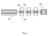
- the microphone comprises a planar substrate arrangement 104.
- An optical source 101 is provided over the substrate arrangement for emitting a light beam 106 in a direction parallel to the substrate arrangement.
- a layer structure defines at least one optical cavity 105 through which the light beam 106 is directed, the cavity having an open top exposed to the sound pressure 107 to be sensed.
- the light beam is directed to a target 102 after passing through the cavity.
- Optical analysis means is provided for determining an optical property which is dependent on the pressure in the cavity, thereby to detect the sound pressure level and hence reconstruct the sound information.
- a series of optical cavities 105 is shown.
- the cavities can be formed in a cover layer 103 or in the substrate itself 104 - either option providing the cavity in a substrate arrangement.
- the target is a light sensor 102 which detects changes in the signal due to the sound waves 107 which change the pressure in the cavities 105.
- the sound pressure wave 107 changes the refractive index of air. This leads to a modulation (amplitude or phase) of the light signal 106 in the cavities 105.
- the modulation can be detected in the separate detector 102 as shown, but it may also be detected as a change in the power consumption or other electrical parameters of the light source 101.
- the target 102 can be an absorber or reflector.
- the modulation is detected based on interferometric effects.
- the path between the light source and the detector has an optical transfer function which is dependent on the refractive index in the cavities.
- the sensitivity of the light source to changes is highest if the light beam is reflected back into the laser cavity. This is partially effected by the sensing cavities.
- the target 102 must then be matched to the interferometer transfer function so that sensitivity is optimal.
- a dielectric reflector can be used that is matched to the sensing cavities.
- the laser can become unstable.
- Using many sensing cavities typically avoids this problem and the target can be omitted, because the light is attenuated enough by the many cavities.
- the large pattern of cavities can form a photonic crystal.
- the refractive index of air depends only slightly on the wavelength, except if close to an absorption line. Therefore, the light source should be chosen that can be most easily integrated or that is close to an absorption line.
- the lithographic requirements are typically more relaxed for longer wavelengths, so that a typical laser will have a wavelength between 300nm and 4000nm.
- Edge emitting lasers require less reflecting mirrors due to the longer amplification path parallel to the wafer surface and are therefore best suited for the sound pressure sensing.
- a preferred example is a distributed feed-back laser that is integrated together with the cavities, or the cavities can be etched after the active laser area is processed. Covers and reflecting layers of the laser can be used to form the cavities.
- the laser can be operated continuously. If the power consumption is to be reduced or if high signals are wanted, e.g., for using the phase matching of harmonic distortions for detecting the refractive index of air, the laser can be pulsed, as outlined in Roberto Macovez, Marina Mariano, Sergio Di Finizio, and Jordi Martorell, Measurement of the dispersion of air and of refractive index anomalies by wavelength-dependent nonlinear interferometry, OPTICS EXPRESS August 2009 / Vol. 17, No. 16 / pp. 13881- 13888 .
- the pulse repetition rate should be much higher than the typical 48kHz sampling rate for audio frequency to allow averaging and noise reduction.
- the wavelength should be adapted to the highest sensitivity, i.e., when the interferometer output amplitude changes most strongly with variations of the refractive index of the air.
- the laser can be slightly tuned by the supply power of the laser. It can also be modulated to build a heterodyne detector as described in J.-P. Monchalin, Optical Detection of Ultrasound, IEEE Tran. UFFC, vol. 33, no. 5, 1986, pp. 485-499 .
- the refractive index of a gas normally increases with higher pressure.
- a higher pressure leads to more molecules in the cavity, which each adds to the susceptibility (Lorentz-Lorenz equation). This means that a pressure change modulates the speed of the light within a cavity as well as the reflectivity of the interfaces of the cavity. Both effects can be used for detection of the pressure change.
- the first effect (of varied refractive index) is more often used. Both effects can also be multiplied by using more cavities in series.
- ⁇ / l ⁇ ⁇ ⁇ P a 2 ⁇ ⁇ / ⁇ ⁇ 1 deg / Pa m .
- optical path length / through air should be as long as possible. This can be achieved by multiple reflections such as in a Fabry-Perot interferometer or by a meandered light path.
- a typical length of a cavity creating by surface micromachining is in the order of a micrometer. This means that many cavities should be used in series.
- each interferometer 201 gives rise to transmission peaks which are dependent on the refractive index of the cavity medium, and therefore dependent on the sound pressure.
- the path between the source 101 and the detector 102 has a transfer function which is dependent on the refractive index, and the detection of peaks at specific frequencies in the light output can be used to derive the refractive index and therefore sound pressure level.
- the light source emits an essentially single frequency, then the output amplitude is modulated by the audio signal.
- the operation is typically at the steep edge of a transmission line (peak in transmission if the frequency would be swept) of the interferometer.
- the light source can also be modulated and the heterodyne signal can be detected in the target. In most cases, the amplitude is detected, and the phase is recovered by using the interferometer principle.
- a positive optical feedback increases the light intensity in the laser cavity and hence lowers the laser threshold power.
- the ratio between spontaneous emission and stimulated emission changes, the light output changes, the power consumption and the voltage across the laser for a given current.
- Many effects further modulate the electrical laser properties. For example the temperature changes by changing the light output, which in turn shift the I(V) characteristic of the laser diode.
- the laser 101 can be a separate device mounted on the substrate 104, or it can be manufactured on the substrate 104 at the same time as the sensor 102.
- the detector and laser can be on separate wafers, which are wafer-bonded or assembled onto another substrate.
- the microphone structure can be integrated onto a single substrate.
- the substrate 104 can be used for the light path instead of a separate layer.
- this invention does not concern the details of the manufacturing of the light source (DFB) or detector.
- an existing edge-emitting laser process on-wafer
- post-processing to form the cavities and sensing structures on it.
- the aspect ratio between the depth of the cavity and the smallest diameter of the cavity should be high enough to avoid too much signal loss, for example the cavity depth should be greater than its smallest lateral dimension.
- cavities 105 can be combined in regular or irregular patterns with well-defined distances to form a photonic bandgap.
- at least one of the lateral widths of the cavity 105 which corresponds to the path length of light across the cavity, should be most conveniently in the order of a wavelength, typically below 1 ⁇ 2 wavelength.
- This allows guiding of the light beam and implementation of photonic bandgap structures or gratings.
- the structures can also be larger, especially in the direction normal to the substrate surface (thickness direction), approaching more the designs of macroscopic interferometers such as Fabry-Perot as outlined above.
- the depth of the cavities is limited and hence the width if the light losses are to be limited.
- the cavities are arranged in this case best in a photonic bandgap structure that channels or focuses the light. Otherwise the optical path length will be effectively shorter or the light will be lost and the signal at the detector weaker, causing more noise. Since the light should travel mostly through the air for maximum pressure sensitivity, an inverted photonic bandgap structure may be best suited. This means that the light is not concentrated in the layer with the higher dielectric constant, but in the air. The cavities then become interconnected and dielectric posts guide the light.
- Figure 3 shows an example of inverted photonic band gap with a cover.
- the sound pressure wave is again shown as 107.
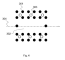
- Dielectric or metal posts 301 are provided over the substrate 104 with cavity resonators 302 defined between the posts.
- a cover with an air access hole 303 is provided over the posts, and the light path 304 is beneath the cover.
- the cavity resonators 302 are defined by leaving out posts, in order to form microresonators or waveguides that can be used to act as cavities. This can be seen in Figure 4 , which is a plan view of the arrangement of Figure 3 using the same reference numerals.
- Photonic bandgap structures e.g, beam-splitters, resonators and waveguides.
- Photonic bandgap structures can be designed in such a way that light can only travel in certain directions, causing a collimation of the beam. This effect can be used together with the construction of diffractive lenses (see, e.g., I. V. Minin, O. V. Minin, Y. R. Triandaphilov and V. V.
- the advantage of using multiple cavities or photonic bandgap structures is a higher signal modulation or a higher tolerance against misalignment.
- the invention enables the use of a solid-state, horizontally emitting laser (e.g., DFB), which has a better stability than a solid state vertical emitting laser (VCSEL).
- DFB solid-state, horizontally emitting laser
- VCSEL solid state vertical emitting laser
- the arrangement can be smaller than existing devices without membranes.
- the use of small cavities allows the detection of a wide range of frequencies without acoustic interference.
- a pressure gradient microphone can be implemented by splitting the optical beam and using two light paths.
- the phase difference between the two paths depends on the pressure at the location of the paths (see above equations).
- the laser beam can be split in multiple paths, comprising a reference path.
- An interferometric set-up that combines the two light beams will only sense the phase difference between the paths, so that the output signal is proportional to the pressure difference at both path locations. If a sound pressure field is homogeneous over the substrate, both paths will experience the same phase shift and hence the resulting phase shift will be zero, so that no output signal is detected. Only if there is a pressure gradient along the substrate, the resulting phase shift will be non-zero. If only one of the paths is exposed to the sound field, "normal" omnidirectional sound sensing will occur in the exposed path. However, if multiple paths are exposed, only the pressure gradient along the substrate surface is sensed. This can be used, e.g., for making directional ultrasound microphones.
- the invention is not limited to any particular detection process, as several interferometer principles can be implemented such as Fabry-Perot, Sagnac, Mach-Zender or Michelson.
- the invention can be used as a microphone in mobile phones, headsets, voice recorders, ultrasound receivers or sound power meters. It may also be used in sonar applications in liquids. If enough stability is achieved, it might also be used as sensor for slow pressure changes.
- the microphone of the invention is particularly suited for fast, high intensity ultrasound receivers. It may also be used in photoacoustic applications as acoustic detector and as modulator as well.
- the source wavelength could be set to the absorption line of a gas that is to be detected by photoacoustic spectroscopy.
Landscapes
- Physics & Mathematics (AREA)
- Engineering & Computer Science (AREA)
- Acoustics & Sound (AREA)
- Signal Processing (AREA)
- Investigating Or Analysing Materials By Optical Means (AREA)
- Electrostatic, Electromagnetic, Magneto- Strictive, And Variable-Resistance Transducers (AREA)
Priority Applications (2)
| Application Number | Priority Date | Filing Date | Title |
|---|---|---|---|
| EP10163441A EP2389014A1 (de) | 2010-05-20 | 2010-05-20 | Mikrofon |
| PCT/IB2011/052068 WO2011145025A1 (en) | 2010-05-20 | 2011-05-11 | Microphone |
Applications Claiming Priority (1)
| Application Number | Priority Date | Filing Date | Title |
|---|---|---|---|
| EP10163441A EP2389014A1 (de) | 2010-05-20 | 2010-05-20 | Mikrofon |
Publications (1)
| Publication Number | Publication Date |
|---|---|
| EP2389014A1 true EP2389014A1 (de) | 2011-11-23 |
Family
ID=43014130
Family Applications (1)
| Application Number | Title | Priority Date | Filing Date |
|---|---|---|---|
| EP10163441A Withdrawn EP2389014A1 (de) | 2010-05-20 | 2010-05-20 | Mikrofon |
Country Status (2)
| Country | Link |
|---|---|
| EP (1) | EP2389014A1 (de) |
| WO (1) | WO2011145025A1 (de) |
Cited By (2)
| Publication number | Priority date | Publication date | Assignee | Title |
|---|---|---|---|---|
| US9903816B2 (en) | 2014-12-02 | 2018-02-27 | Infineon Technologies Ag | Photonic crystal sensor structure and a method for manufacturing the same |
| US20240068990A1 (en) * | 2022-08-29 | 2024-02-29 | Government Of The United States Of America, As Represented By The Secretary Of Commerce | Sound pressure metrology instrument and determining sound pressure from index of refraction |
Families Citing this family (1)
| Publication number | Priority date | Publication date | Assignee | Title |
|---|---|---|---|---|
| DE102022113109A1 (de) | 2022-05-24 | 2023-11-30 | Ams-Osram Ag | Mikrofon und verfahren zum betrieb eines mikrofons |
Citations (9)
| Publication number | Priority date | Publication date | Assignee | Title |
|---|---|---|---|---|
| US3625616A (en) * | 1969-06-25 | 1971-12-07 | Bendix Corp | Interferometric pressure sensor |
| US4422167A (en) * | 1981-06-25 | 1983-12-20 | The United States Of America As Represented By The Secretary Of The Navy | Wide-area acousto-optic hydrophone |
| JPS6018100A (ja) * | 1983-07-11 | 1985-01-30 | Yasushi Miki | マイクロホン |
| US6542244B1 (en) * | 1999-12-07 | 2003-04-01 | Harris Corporation | Variable sensitivity acoustic transducer |
| US6674778B1 (en) * | 2002-01-09 | 2004-01-06 | Sandia Corporation | Electrically pumped edge-emitting photonic bandgap semiconductor laser |
| US20040013156A1 (en) * | 2002-07-18 | 2004-01-22 | Hongyu Deng | Edge emitting lasers using photonic crystals |
| DE102006013345A1 (de) * | 2006-03-23 | 2007-10-04 | Lukas Balthasar Fischer | Elektroakustischer Wandler, insbesondere optisches Mikrofon ohne Membran |
| WO2008000007A1 (de) * | 2006-06-27 | 2008-01-03 | Nxp B.V. | Elektroakustischer wandler |
| WO2010029509A1 (en) * | 2008-09-12 | 2010-03-18 | Nxp B.V. | Transducer system |
-
2010
- 2010-05-20 EP EP10163441A patent/EP2389014A1/de not_active Withdrawn
-
2011
- 2011-05-11 WO PCT/IB2011/052068 patent/WO2011145025A1/en not_active Ceased
Patent Citations (9)
| Publication number | Priority date | Publication date | Assignee | Title |
|---|---|---|---|---|
| US3625616A (en) * | 1969-06-25 | 1971-12-07 | Bendix Corp | Interferometric pressure sensor |
| US4422167A (en) * | 1981-06-25 | 1983-12-20 | The United States Of America As Represented By The Secretary Of The Navy | Wide-area acousto-optic hydrophone |
| JPS6018100A (ja) * | 1983-07-11 | 1985-01-30 | Yasushi Miki | マイクロホン |
| US6542244B1 (en) * | 1999-12-07 | 2003-04-01 | Harris Corporation | Variable sensitivity acoustic transducer |
| US6674778B1 (en) * | 2002-01-09 | 2004-01-06 | Sandia Corporation | Electrically pumped edge-emitting photonic bandgap semiconductor laser |
| US20040013156A1 (en) * | 2002-07-18 | 2004-01-22 | Hongyu Deng | Edge emitting lasers using photonic crystals |
| DE102006013345A1 (de) * | 2006-03-23 | 2007-10-04 | Lukas Balthasar Fischer | Elektroakustischer Wandler, insbesondere optisches Mikrofon ohne Membran |
| WO2008000007A1 (de) * | 2006-06-27 | 2008-01-03 | Nxp B.V. | Elektroakustischer wandler |
| WO2010029509A1 (en) * | 2008-09-12 | 2010-03-18 | Nxp B.V. | Transducer system |
Non-Patent Citations (3)
| Title |
|---|
| D. HEINIS; C. GORECKI; S. BARGIEL; B. CRETIN: "Feedback-induced voltage change of a Vertical-Cavity Surface-Emitting Laser as an active detection system for miniature optical scanning probe microscopes", OPTICS EXPRESS, vol. 14, no. 8, April 2006 (2006-04-01), pages 3396 - 3405 |
| J.-P. MONCHALIN: "Optical Detection of Ultrasound", IEEE TRAN. UFFC, vol. 33, no. 5, 1986, pages 485 - 499 |
| ROBERTO MACOVEZ; MARINA MARIANO; SERGIO DI FINIZIO; JORDI MARTORELL: "Measurement of the dispersion of air and of refractive index anomalies by wavelength-dependent nonlinear interferometry", OPTICS EXPRESS, vol. 17, no. 16, August 2009 (2009-08-01), pages 13881 - 13888 |
Cited By (2)
| Publication number | Priority date | Publication date | Assignee | Title |
|---|---|---|---|---|
| US9903816B2 (en) | 2014-12-02 | 2018-02-27 | Infineon Technologies Ag | Photonic crystal sensor structure and a method for manufacturing the same |
| US20240068990A1 (en) * | 2022-08-29 | 2024-02-29 | Government Of The United States Of America, As Represented By The Secretary Of Commerce | Sound pressure metrology instrument and determining sound pressure from index of refraction |
Also Published As
| Publication number | Publication date |
|---|---|
| WO2011145025A1 (en) | 2011-11-24 |
Similar Documents
| Publication | Publication Date | Title |
|---|---|---|
| US7518737B2 (en) | Displacement-measuring optical device with orifice | |
| US7440117B2 (en) | Highly-sensitive displacement-measuring optical device | |
| US7116430B2 (en) | Highly-sensitive displacement-measuring optical device | |
| US6901101B2 (en) | Optical sensor for measuring physical and material properties | |
| US9641941B2 (en) | Transducer system | |
| CN103776384B (zh) | 光纤耦合光子晶体平板应变传感器、系统以及制作和使用方法 | |
| EP2710335B1 (de) | Optischer sensor | |
| US10495508B2 (en) | Phase-front-modulation sensor | |
| US8730484B2 (en) | Resonant cavity sensor having multiple input optical signals at different angles | |
| US20240426650A1 (en) | Optical fiber with an acoustically sensitive fiber bragg grating and ultrasound sensor including the same | |
| CA2269828A1 (en) | Integrated interferometer | |
| EP2389014A1 (de) | Mikrofon | |
| EP4081770B1 (de) | Optische vorrichtung zur erfassung einer schallwelle | |
| US11808654B2 (en) | Integrated optical transducer and method for detecting dynamic pressure changes | |
| US7551295B2 (en) | Displacement sensor | |
| EP3742757B1 (de) | Optischer wandler und verfahren zur messung einer verschiebung | |
| US20250035496A1 (en) | Optical fiber system to determine at least one physical parameter and method to determine at least one physical parameter using an optical fiber system | |
| Aikio et al. | Extremely short external cavity lasers: the use of wavelength tuning effects in near field sensing | |
| AU2014218457A1 (en) | Optical sensor | |
| Minasamudram | Optimization of wideband fiber optic hydrophone probe for ultrasound sensing applications | |
| Solgaard | Optical Displacement Sensors |
Legal Events
| Date | Code | Title | Description |
|---|---|---|---|
| AK | Designated contracting states |
Kind code of ref document: A1 Designated state(s): AL AT BE BG CH CY CZ DE DK EE ES FI FR GB GR HR HU IE IS IT LI LT LU LV MC MK MT NL NO PL PT RO SE SI SK SM TR |
|
| AX | Request for extension of the european patent |
Extension state: BA ME RS |
|
| PUAI | Public reference made under article 153(3) epc to a published international application that has entered the european phase |
Free format text: ORIGINAL CODE: 0009012 |
|
| RAP1 | Party data changed (applicant data changed or rights of an application transferred) |
Owner name: KNOWLES ELECTRONICS ASIA PTE. LTD. |
|
| STAA | Information on the status of an ep patent application or granted ep patent |
Free format text: STATUS: THE APPLICATION IS DEEMED TO BE WITHDRAWN |
|
| 18D | Application deemed to be withdrawn |
Effective date: 20120524 |