EP2389059A2 - Tête à implanter pour un automate d'alimentation, automate d'alimentation et procédé d'alimentation - Google Patents
Tête à implanter pour un automate d'alimentation, automate d'alimentation et procédé d'alimentation Download PDFInfo
- Publication number
- EP2389059A2 EP2389059A2 EP11166546A EP11166546A EP2389059A2 EP 2389059 A2 EP2389059 A2 EP 2389059A2 EP 11166546 A EP11166546 A EP 11166546A EP 11166546 A EP11166546 A EP 11166546A EP 2389059 A2 EP2389059 A2 EP 2389059A2
- Authority
- EP
- European Patent Office
- Prior art keywords
- placement head
- placement
- receiving device
- frame element
- head module
- Prior art date
- Legal status (The legal status is an assumption and is not a legal conclusion. Google has not performed a legal analysis and makes no representation as to the accuracy of the status listed.)
- Granted
Links
Images

Classifications
-
- H—ELECTRICITY
- H05—ELECTRIC TECHNIQUES NOT OTHERWISE PROVIDED FOR
- H05K—PRINTED CIRCUITS; CASINGS OR CONSTRUCTIONAL DETAILS OF ELECTRIC APPARATUS; MANUFACTURE OF ASSEMBLAGES OF ELECTRICAL COMPONENTS
- H05K13/00—Apparatus or processes specially adapted for manufacturing or adjusting assemblages of electric components
- H05K13/04—Mounting of components, e.g. of leadless components
- H05K13/0404—Pick-and-place heads or apparatus, e.g. with jaws
Definitions
- the invention relates to a placement for a placement for loading substrates with components. Furthermore, the invention relates to a placement for loading of substrates with components and an assembly method for equipping substrates with components.
- substrates for example printed circuit boards
- the components are equipped with components of various types with the aid of so-called placement machines.
- the components may be mechanical or electronic in nature.
- the components are provided by laterally arranged at the placement feeders at defined pickup positions.
- a placement head of the placement machine which can be moved by a positioning system picks up the components at the pick-up positions and transfers them to a placement area of the placement machine, where they are positioned on provided substrates.
- the substrates to be loaded are fed to the placement area via a transport device. Ready-assembled substrates are transported back out of the placement area via this transport device.
- the components can be checked by means of a suitable detection device, for example a component camera, with regard to their position relative to the placement head and with regard to any errors.
- placement heads for the various applications or requirements, each one cover a specific area of application. For example, applications in the speed range or in the flex area are served by different placement heads. Should an application or a requirement change with a customer, the placement heads of the placement machine can be exchanged. The same applies to a defect at the placement. Again, either the entire placement head is replaced or the placement is repaired in the placement machine. Since the placement heads are usually technically complex and ergonomically difficult to access, a repair of parts of the placement is very difficult and requires a stoppage of the machine and often the entire line resulting in economic damage to the operator. Although the placement can be very easily attached to the placement, so that a replacement is easy vonstatten alliance, but the complete replacement of a placement is very expensive, as a replacement a new placement head must be present.
- the object of the invention is to provide a placement for a placement machine for equipping substrates with components that is modular and simple, which is inexpensive and can be mounted and disassembled in a simple manner different placement head modules. Furthermore, to create a simple and flexible placement machine and a simple and flexible loading of substrates with components are made possible by a simple and modular placement.
- the object is achieved by a placement head for a placement machine for equipping substrates with components, wherein the placement head has a frame element for mounting placement modules, wherein the frame element has two or more interfaces, each for transmitting energy, Data and / or air are each formed to a placement head module, and wherein at least two interfaces of the frame member are formed identical.
- the placement head can be configured very easily according to the customer and requirements.
- Such a configuration of the placement allows a configuration of the placement with externally identically designed placement modules.
- the fitting head modules fastened to the frame element of the placement head can be designed in a standardized manner, since at least two, preferably all, of the interfaces of the frame element are formed identically.
- a placement head module is defective, this can be easily replaced by a same placement head module.
- the interfaces on the placement head modules are also preferably all identically designed to be complementary to the interfaces of the frame element.
- Such a trained placement can be easily reconfigured depending on the application and requirements of the customer. That is, individual placement head modules can be easily replaced by other placement head modules.
- Both the assembly and disassembly of a placement head module are easy to perform by the standardized interfaces of the frame member and the placement head modules. If a placement head module is defective, it can be simple, inexpensive and quickly replaced by a new placement head module. It is no longer necessary to swap the entire placement head.
- the identically designed interfaces provide a simple interface to the operator. The simplification and standardization of the interfaces is particularly advantageous because the placement head modules are very maintenance-intensive due to the high mechanical stress over the life and in their entirety are complex to the operator.
- all interfaces of the frame element are identical.
- All placement head modules can also be standardized.
- Standard or identical design in connection with the placement head modules means in the sense of the invention that the outer dimensions and the arrangement of the interfaces is the same for all placement head modules, so that they can be easily connected to the identically designed interfaces of the frame element. It can be disassembled as needed from one or more placement modules of the placement and replaced by one or more other placement head modules.
- each interface is part of a receiving device of the frame member, each receiving device is designed for positive reception of a respective Be Glakopfmoduls. That is, the frame member has two or more receiving means, each receiving means having an interface for transmitting power, data and / or air.
- the interfaces preferably have direct contacts with contact pins for the transmission of data and energy or couplings for the air supply. The transmission of data and energy can also be made contactless.
- the identically designed interfaces of the frame element for the transmission of energy, data and air educated.
- each different placement head module can be connected to each interface. But it is also possible that two or more interfaces are designed only for the transmission of energy and data.
- the receiving devices are used for positive reception of the placement head modules, that is, for adjustment but also for fixing the placement head modules. Due to the positive reception of the placement head modules in the receiving devices, the placement head modules are automatically brought correctly to the appropriate interfaces, so that the interfaces of the placement head modules can be positioned in alignment with the interfaces of the frame member and connected accordingly.
- the receiving devices for the positive reception of each placement module are preferably designed garage-shaped. That is, the receiving means advantageously have side walls which serve as guides for insertion of a placement head module. This ensures that the placement head modules are automatically inserted correctly into the receiving devices and can be properly connected to the corresponding interfaces of the frame element.
- all receiving devices of the frame element have identically formed receiving spaces. This allows all placement head modules to have standardized outside dimensions, so that each placement head module can be inserted and connected to each receiving device.
- the placement head modules can be designed differently in the interior.
- each one Receiving device advantageously has fixing elements in order to securely hold the insertion head module completely inserted into the receiving device.
- the fixing elements are designed such that they securely hold the fully inserted placement head module which is connected to the interface of the frame member.
- the fixing elements can have latching devices and / or plug-in connections, so that a simple fixing of a placement head module to a receiving device is made possible.
- simple fixing elements are preferred, so that the dismantling of a placement head module can easily take place on a receiving device.
- a fixing element may be formed as a cover element, which is arranged to be pivotable and / or rotatable on the receiving device.
- a placement head is preferred in which at least one receiving device of the frame element is arranged so as to be displaceable on the frame element in one, two and / or three dimensions.
- a receiving device in the z-direction that is to say in the direction of a substrate, be movable.
- a receiving device of the frame element in the x-direction, in the y-direction and in the z-direction can be arranged displaceably on the frame element.
- the placement is particularly flexible configurable with placement head modules.
- corresponding guide elements in particular linear guides, provided on each receiving device along which a placement head module in the receiving space of a receiving device is positively inserted until the interface of the placement head module is connected to the interface of the frame member or the receiving device.
- the at least one receiving device arranged displaceably on the frame element can be displaced manually, for example.
- a placement head wherein the at least one displaceably arranged receiving device by one or more drive units, in particular by one or more linear motor (s), is displaceable.
- each receiving device has a locking element for fixing a placement head module to the receiving device.
- a placement head module introduced in a form-fitting manner into a receiving device is fixed in its end position in the receiving space of the receiving device, so that the placement head module is securely fixed in the receiving device or on the frame element.
- the locking element can be designed in various ways. For example, latching, snap or plug elements can be provided.
- a pivotable and / or rotatable lid can be provided for fixing a placement head module. The fixation can be advantageously carried out by screw.
- the placement head can be provided in the placement head that the frame member is attached to a one or two-dimensionally displaceable support means.
- This carrier device often referred to as a carrier, is preferably movable parallel to the transported on a transport device of a placement substrate.
- the carrier device can be movable in one or two dimensions, that is to say in the x-direction and / or in the y-direction.
- the fixing of the frame member is realized on the support means by simple fastening means, so that a quick assembly and disassembly of the frame member is made possible on or from the support means.
- the placement head modules can be designed in various ways.
- a placement head module as an actuator element or as Be formed sensor element.
- a placement head module can be designed, for example, for a so-called speed range.
- Such placement head modules are designed for rapid assembly of a substrate, in particular a printed circuit board.
- a placement head module can be designed for a so-called flex area.
- Such placement head modules are designed for the variable placement of a substrate, in particular a printed circuit board.
- an actuator element may be a so-called pick & place module.
- a sensor element can be designed, for example, for automatic optical inspection (AOI).
- AOI automatic optical inspection
- a sensor element can have optical measuring functions.
- a placement head module can be designed as a gripper or as a dispenser for adhesive or flux.
- Each placement head module preferably has corresponding electronics. That is, preferred is a placement, in which each placement head module has its own electronics and a separate control unit for controlling the electronics of the respective placement head module.
- the placement head in particular the frame element, have a central control unit for controlling the electronics of at least two placement head modules. This central solution allows the placement head modules to be made simpler.
- a central control unit can be provided on the placement head, in particular on the frame element, for all placement head modules that can be connected to the frame element. It is also advantageous in the placement when the electronics of each Placement head module for storing the type, calibration data, manufacturing date; of the technical state and / or the number of cycles of the placement head module is formed.
- the electronics of a placement head module can also be designed to store further data and information. Due to the easy interchangeability of Be Nativekopfmodule of the frame member and the receiving means of the frame element, the downtime of a placement can be reduced. Standardized placement head modules and a placement head designed in this way enable a very short repair time in the event of a service, since the complexity of the placement head is divided into small units and encapsulated.
- each receiving device fastening elements for releasably securing a placement head module via complementary trained Schmidtfest Trents institute of Be Glakopfmodul, wherein the fasteners as latching, plug and / or Bayonet closure elements are formed.
- Such fasteners allow a simple and in particular fast attachment of a placement head module to a receiving device of a frame element.
- a simple and rapid disassembly of the placement head module on the receiving device is ensured. This allows a placement head module can be easily and quickly replaced by another placement head module without the entire placement must be replaced. Due to the simple and quick replacement possibility of individual placement head module, the flexibility of the placement is increased.
- the fastening elements are designed as latching or plug-in elements.
- snap-in or plug-in elements can be a quick attachment of a Placement head module take place on a receiving device, wherein the placement head module has complementary counter-fastening elements.
- the latching or plug-in elements of the receiving devices are designed as latching receptacles or plug-in receptacles.
- the quick-change capability of a placement head module of a receiving device is made possible by the fact that the receiving device and placement modules have in particular complementary and position-defined, ie fixed, attachment interfaces and location-defined interfaces for transmitting energy, data and / or air.
- the fastening elements of the receiving devices together with the counter-fastening elements of the placement head modules so-called quick-release couplings, which allow easy and quick attachment of placement modules on the receiving devices, but also a quick and easy release of placement modules of the receiving devices.
- a placement head that the interfaces of a receiving device and the fastening elements of the one receiving device are arranged on the receiving device such that the attachment of a placement head module to the interfaces and to the fastening elements of the receiving device by plugging or pushing of the placement head module along a fastening direction, in particular a rectilinear fastening direction, is made possible.
- An advantage of such a placement head is that little space or mounting space for physically mounting the placement head modules to the receiving devices, as well as for connection to the interfaces for the transmission of energy, data and / or air to the placement modules is required.
- the fasteners as well as the interfaces of the receiving devices advantageously require the same mounting direction of the placement head modules.
- each one Placement head module can be introduced along a fastening direction, in particular a rectilinear mounting direction, in a corresponding receiving device, wherein at the same time the physical attachment of the placement module to the fasteners of the receiving device, as well as the connection to the interfaces for the transmission of energy, data and / or air takes place.
- This saves considerable installation effort, as well as assembly time for mounting and disassembly of a placement module to or from a receiving device.
- a trained placement head in particular by the positive reception, an automatic centering of a placement head module on a receiving device, without requiring additional manipulations are required.
- Both the fastening elements of the receiving device, as well as the interfaces for energy, data and / or air can be accommodated in such a fastening of the placement head module along a straight mounting direction in a tight space.
- Such a placement can be quickly adapted to different placement tasks with little effort, without having to be removed from the placement machine.
- each receiving device has adjusting means for displacing a picked placement head module for one, two and / or three-dimensional displacement of the accommodated placement head module relative to the receiving device.
- the receiving means may comprise adjusting means which enable a picked placement head module to be moved within a receiving means in an x, y and / or z direction without the secure placement Attachment and the connection to the interfaces for energy, data and / or air to lose.
- the adjusting means may be, for example, guide rails with locks.
- the object is achieved by an automatic placement machine for equipping substrates with the components, wherein the placement machine has at least one placement head according to the first aspect of the invention.
- a trained placement machine is particularly flexible and allows a small downtime in case of failure in the at least one placement.
- the object is achieved by a placement method for loading substrates, in which a placement head according to the first aspect of the invention is used.
- a placement head according to the first aspect of the invention makes it possible to carry out a placement process quickly and easily. In particular, a quick troubleshooting, maintenance and reconfiguration of the placement to changed placement orders or applications by the use of such placement is possible.
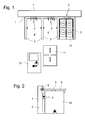
- FIG. 1 is a schematic sectional view of a frame element 1 of a placement, which is designed according to the construction principle of the invention shown.
- the frame element 1 is designed for fastening assembly head modules 10, 11, 12, which are designed in particular as actuator elements or as sensor elements.
- the frame element 1 has three interfaces 2, which are each designed to transmit energy, data and air to a respective placement head module 10, 11, 12. All three interfaces 2 of the frame element 1 are identical.
- the frame element 1 has three receiving devices 3, each having a receiving space 4 for receiving a placement head module 10, 11, 12.
- the receiving devices 3 and the receiving spaces 4 of the receiving devices 3 are formed identically, so that the insertable insertion head modules 10, 11, 12 can be standardized.
- the placement head modules 10, 11, 12 are formed of the same size of their outer dimensions, so that each placement head module 10, 11, 12 in each receiving device 3 is positively inserted and with the interfaces 2 of the frame member 1 is easily connectable.
- the placement head module 10 is seated in the right-hand receiving device 3 of the three receiving devices 3, while the placement head modules 11, 12 are arranged in front of the corresponding receiving devices 3.
- the frame element 1 is fastened to a carrier device 7 of the placement head.
- the carrier device 7 is preferably movable parallel to the substrate transported on a transport device.
- FIG. 2 schematically shows in a side view of a mounted on a frame member 1 placement head module 12.
- a locking element 6 here in the form of a cover member, provided which the placement head module 12 in its end position in which it is connected to the interface 2 of the frame member 1 , fixed.
- the locking element 6 advantageously has latching elements for gripping around the placement head module 12.
- the cover element 6 is held pivotably about an axis 8 on the receiving device 3 of the frame element 1.
- FIG. 3 is another frame member 1 of a placement shown in a schematic sectional view.
- the frame element 1 has three receiving devices 3 for receiving placement modules 12.
- the receiving devices 3 or the receiving spaces 4 of the receiving devices 3 and the interfaces 2 of the frame element 1 and the individual receiving devices 3 are identical, so that in any receiving device 3, any placement head module 10, 11, 12 can be inserted.
- a displaceable receiving device 3a In comparison to the frame element 1 according to FIG. 1 has the frame element 1 of FIG. 3 a displaceable receiving device 3a. That is, two receiving devices 3 are arranged immovably on the frame element 1, while a third receiving device 3a is arranged movably on the frame element in the z-direction.
- the stationary receiving devices 3 are preferably formed integrally with the frame element 1.
- the displaceable receiving device 3 a is held displaceably on the frame element 1 via bearings 9.
- a displaceable receiving device 3a is particularly useful when different configurations of the placement are required and result in different z-strokes / levels
- the displaceable arrangement of the receiving device 3a on the frame element 1 is in FIG. 4 shown schematically in a side view.
- the receiving device 3a is on the frame element 1 slidably mounted.
- the receiving device 3a by drive unit 5, in particular electric drives, such as a linear motor in the z-direction up or down are driven.
- the cover element 6 is held pivotably about an axis 8 on the receiving device 3 a.
- the placement head modules can be designed differently.
- a corresponding electronics is integrated in the placement head modules.
- the differently designed placement modules can be supplied with data, air and energy.
- a placement head module can be designed, for example, for automatic optical inspection (AOI). By means of suitable image processing methods, such a placement head module can find defects on a component to be equipped or on the positioning of a component on the substrate.
- AOI automatic optical inspection
Landscapes
- Engineering & Computer Science (AREA)
- Manufacturing & Machinery (AREA)
- Microelectronics & Electronic Packaging (AREA)
- Supply And Installment Of Electrical Components (AREA)
Applications Claiming Priority (1)
| Application Number | Priority Date | Filing Date | Title |
|---|---|---|---|
| DE102010021069.2A DE102010021069B4 (de) | 2010-05-19 | 2010-05-19 | Bestückkopf für einen Bestückautomaten, Bestückautomat sowie Bestückverfahren |
Publications (3)
| Publication Number | Publication Date |
|---|---|
| EP2389059A2 true EP2389059A2 (fr) | 2011-11-23 |
| EP2389059A3 EP2389059A3 (fr) | 2013-08-14 |
| EP2389059B1 EP2389059B1 (fr) | 2016-06-22 |
Family
ID=44468709
Family Applications (1)
| Application Number | Title | Priority Date | Filing Date |
|---|---|---|---|
| EP11166546.9A Active EP2389059B1 (fr) | 2010-05-19 | 2011-05-18 | Tête à implanter pour un automate d'alimentation, automate d'alimentation et procédé d'alimentation |
Country Status (4)
| Country | Link |
|---|---|
| EP (1) | EP2389059B1 (fr) |
| JP (1) | JP5086463B2 (fr) |
| CN (1) | CN102264217B (fr) |
| DE (1) | DE102010021069B4 (fr) |
Cited By (2)
| Publication number | Priority date | Publication date | Assignee | Title |
|---|---|---|---|---|
| CN104977921A (zh) * | 2014-04-07 | 2015-10-14 | 韩华泰科株式会社 | 用于自动监视装置故障的系统和方法 |
| EP3780931A4 (fr) * | 2018-03-30 | 2021-03-31 | Fuji Corporation | Tête de montage |
Families Citing this family (4)
| Publication number | Priority date | Publication date | Assignee | Title |
|---|---|---|---|---|
| JP6280822B2 (ja) * | 2014-06-13 | 2018-02-14 | ヤマハ発動機株式会社 | 部品実装装置、及びアクチュエータシステム |
| CN107072064B (zh) * | 2017-01-13 | 2019-01-22 | 深圳市海能达通信有限公司 | 一种结构元件置件的方法 |
| DE102018103398B4 (de) * | 2018-02-15 | 2019-10-10 | Asm Assembly Systems Gmbh & Co. Kg | Pneumatisch aktuierbares Federelement zum Steuern der auf ein Bauelement wirkenden Bestückkraft |
| CN118434122B (zh) * | 2024-07-05 | 2024-11-05 | 华博研创电子科技(江苏)有限公司 | 一种电子元器件贴装设备 |
Family Cites Families (12)
| Publication number | Priority date | Publication date | Assignee | Title |
|---|---|---|---|---|
| DE19919924A1 (de) * | 1999-04-30 | 2000-11-16 | Siemens Ag | Verfahren zum Betrieb eines Bestückautomaten, Bestückautomat, auswechselbare Komponente für einen Bestückautomaten und System aus einem Bestückautomaten und einer auswechselbaren Komponente |
| JP3960054B2 (ja) * | 2002-01-21 | 2007-08-15 | 松下電器産業株式会社 | 電子部品実装装置および電子部品の実装ヘッドユニット |
| DE10202290A1 (de) * | 2002-01-22 | 2003-07-31 | Siemens Ag | Bestückkopf und Bestückverfahren zum Bestücken von Substraten mit Bauelementen |
| DE102005027901A1 (de) * | 2005-06-16 | 2006-12-28 | Siemens Ag | Bestückkopf für einen Bestückautomaten zum Bestücken von Substraten mit elektrischen Bauteilen |
| CN100446652C (zh) * | 2006-07-04 | 2008-12-24 | 北京航空航天大学 | 高速全自动贴片机微型模块化贴装头 |
| KR100816071B1 (ko) * | 2006-09-22 | 2008-03-24 | 미래산업 주식회사 | 전자부품 픽커 및 이를 구비한 핸들러용 헤드 어셈블리 |
| CN101102551A (zh) * | 2007-08-07 | 2008-01-09 | 中兴通讯股份有限公司 | 一种携带接收者称呼的短消息的实现方法 |
| DE102007046429A1 (de) * | 2007-09-28 | 2008-12-04 | Siemens Ag | Aufnehmen mehrerer elektronischer Bauelementen mittels einer konfigurierbaren Bauelement-Aufnahmevorrichtung |
| JP4849057B2 (ja) * | 2007-11-09 | 2011-12-28 | パナソニック株式会社 | 電子部品実装装置およびノズル装着履歴データ管理方法 |
| JP4893702B2 (ja) * | 2008-07-01 | 2012-03-07 | パナソニック株式会社 | 部品実装関連作業機 |
| DE102008049540B3 (de) * | 2008-09-30 | 2010-04-22 | Siemens Electronics Assembly Systems Gmbh & Co. Kg | Anordnung zum Wechseln eines Bestückkopfs und Bestückautomat |
| JP5750235B2 (ja) * | 2010-04-29 | 2015-07-15 | 富士機械製造株式会社 | 製造作業機 |
-
2010
- 2010-05-19 DE DE102010021069.2A patent/DE102010021069B4/de active Active
-
2011
- 2011-05-18 EP EP11166546.9A patent/EP2389059B1/fr active Active
- 2011-05-19 CN CN201110130223.6A patent/CN102264217B/zh active Active
- 2011-05-19 JP JP2011112558A patent/JP5086463B2/ja active Active
Non-Patent Citations (1)
| Title |
|---|
| None |
Cited By (2)
| Publication number | Priority date | Publication date | Assignee | Title |
|---|---|---|---|---|
| CN104977921A (zh) * | 2014-04-07 | 2015-10-14 | 韩华泰科株式会社 | 用于自动监视装置故障的系统和方法 |
| EP3780931A4 (fr) * | 2018-03-30 | 2021-03-31 | Fuji Corporation | Tête de montage |
Also Published As
| Publication number | Publication date |
|---|---|
| JP5086463B2 (ja) | 2012-11-28 |
| DE102010021069A1 (de) | 2011-11-24 |
| CN102264217A (zh) | 2011-11-30 |
| DE102010021069B4 (de) | 2015-10-29 |
| EP2389059B1 (fr) | 2016-06-22 |
| JP2011243989A (ja) | 2011-12-01 |
| CN102264217B (zh) | 2015-06-17 |
| EP2389059A3 (fr) | 2013-08-14 |
Similar Documents
| Publication | Publication Date | Title |
|---|---|---|
| EP2389059B1 (fr) | Tête à implanter pour un automate d'alimentation, automate d'alimentation et procédé d'alimentation | |
| DE112013002297B4 (de) | Modul zum Austauschen einer Schnittstelleneinheit in einem Testsystem zum Testen von Halbleiterbauelementen und Testsystem mit einem solchen Modul | |
| DE10302103A1 (de) | Montageeinrichtung für elektronische Bauteile und Montagekopfeinheit für elektronische Bauteile | |
| DE102007020779B3 (de) | Bestückautomat zum Bestücken von elektrischen und/oder optischen Bauteilen auf Substrate | |
| EP2916995B1 (fr) | Installation de production destinée à la fabrication d'un ensemble constitué de plusieurs pièces | |
| DE102015113396B4 (de) | Bestückautomat, Handhabungssystem und Bestücksystem mit einem an einem Bestückautomaten lösbar angebrachten Handhabungssystem | |
| EP2111091B1 (fr) | Agencement de transport de substrats, agencement de manipulation de substrats, agencement de fabrication de composants électroniques ainsi que procédé de manipulation de substrats | |
| DE112015006990T5 (de) | Rotationskopf und Oberflächen-Montagevorrichtung | |
| DE102013105220B3 (de) | Vorrichtung zur Handhabung von Objektträgern mit wahlweise aufnehmbaren Glas- oder Tape-Eindeckmodulen | |
| DE10053232C2 (de) | Substrat-Zuführungsmodul und System aus Substrat-Zuführungsmodul und Arbeitsstation | |
| DE102017124571B4 (de) | Halte- und Antriebseinrichtung, Werkzeugeinrichtung, Ergänzungswerkzeugeinrichtung von einer modular aufgebauten Bauelement-Handhabungsvorrichtung, Vorrichtung zum Handhaben von Bauelementen sowie Verfahren zum anwendungsspezifischen Konfigurieren einer solchen Vorrichtung | |
| DE102007009867A1 (de) | Abbildungsvorrichtung mit auswechselbaren Blenden sowie Verfahren hierzu | |
| EP1954115B1 (fr) | Tête à implanter multiple dotée d'un entraînement rotatif collectif et d'un entraînement d'élévation mobile pour dispositifs de retenue de composants | |
| DE102008049540B3 (de) | Anordnung zum Wechseln eines Bestückkopfs und Bestückautomat | |
| EP4146409B1 (fr) | Système d'essai pour un grand nombre d'objets d'essai qui peuvent être séparés | |
| DE10159165B4 (de) | Vorrichtung zum Messen und/oder Kalibrieren eines Testkopfes | |
| WO2019121089A1 (fr) | Dispositif de commande de bioprocessus et système de bioprocessus | |
| DE112023006505T5 (de) | Chip-Zuführvorrichtung | |
| DE102008031233B3 (de) | Bestückautomat zum Bestücken von Substraten mit Bauteilen | |
| DE102005013283B4 (de) | Bestückautomat zum Bestücken von Substraten mit elektrischen Bauelementen | |
| EP1908340B1 (fr) | Dispositif modulaire permettant d'equiper des substrats | |
| DE102024111273B3 (de) | Transfer von Shuttle-Bestückmodulen zwischen einer Führungsbahn und einer Aufnahmestruktur in einem Shuttle-Bestückmodul-Bestücksystems | |
| DE102008046739B3 (de) | Pipette, Anordnung zum Kalibrieren einer wechselbaren Komponente, Positioniersystem, Bestückautomat sowie Messverfahren | |
| DE102008002756A1 (de) | Vorrichtung zum Vermessen oder Inspizieren von Substraten der Halbleiterindustrie | |
| DE102009014008B4 (de) | Anordnung zur optischen Inspektion von Bestückungsvorgängen |
Legal Events
| Date | Code | Title | Description |
|---|---|---|---|
| AK | Designated contracting states |
Kind code of ref document: A2 Designated state(s): AL AT BE BG CH CY CZ DE DK EE ES FI FR GB GR HR HU IE IS IT LI LT LU LV MC MK MT NL NO PL PT RO RS SE SI SK SM TR |
|
| AX | Request for extension of the european patent |
Extension state: BA ME |
|
| PUAI | Public reference made under article 153(3) epc to a published international application that has entered the european phase |
Free format text: ORIGINAL CODE: 0009012 |
|
| PUAL | Search report despatched |
Free format text: ORIGINAL CODE: 0009013 |
|
| AK | Designated contracting states |
Kind code of ref document: A3 Designated state(s): AL AT BE BG CH CY CZ DE DK EE ES FI FR GB GR HR HU IE IS IT LI LT LU LV MC MK MT NL NO PL PT RO RS SE SI SK SM TR |
|
| AX | Request for extension of the european patent |
Extension state: BA ME |
|
| RIC1 | Information provided on ipc code assigned before grant |
Ipc: H05K 13/04 20060101AFI20130709BHEP |
|
| 17P | Request for examination filed |
Effective date: 20140214 |
|
| RAX | Requested extension states of the european patent have changed |
Extension state: ME Payment date: 20140214 Extension state: BA Payment date: 20140214 |
|
| RBV | Designated contracting states (corrected) |
Designated state(s): AL AT BE BG CH CY CZ DE DK EE ES FI FR GB GR HR HU IE IS IT LI LT LU LV MC MK MT NL NO PL PT RO RS SE SI SK SM TR |
|
| DAX | Request for extension of the european patent (deleted) | ||
| GRAP | Despatch of communication of intention to grant a patent |
Free format text: ORIGINAL CODE: EPIDOSNIGR1 |
|
| INTG | Intention to grant announced |
Effective date: 20160211 |
|
| GRAS | Grant fee paid |
Free format text: ORIGINAL CODE: EPIDOSNIGR3 |
|
| GRAA | (expected) grant |
Free format text: ORIGINAL CODE: 0009210 |
|
| AK | Designated contracting states |
Kind code of ref document: B1 Designated state(s): AL AT BE BG CH CY CZ DE DK EE ES FI FR GB GR HR HU IE IS IT LI LT LU LV MC MK MT NL NO PL PT RO RS SE SI SK SM TR |
|
| REG | Reference to a national code |
Ref country code: GB Ref legal event code: FG4D Free format text: NOT ENGLISH |
|
| REG | Reference to a national code |
Ref country code: CH Ref legal event code: EP |
|
| REG | Reference to a national code |
Ref country code: IE Ref legal event code: FG4D Free format text: LANGUAGE OF EP DOCUMENT: GERMAN |
|
| REG | Reference to a national code |
Ref country code: AT Ref legal event code: REF Ref document number: 808326 Country of ref document: AT Kind code of ref document: T Effective date: 20160715 |
|
| REG | Reference to a national code |
Ref country code: DE Ref legal event code: R096 Ref document number: 502011009992 Country of ref document: DE |
|
| REG | Reference to a national code |
Ref country code: NL Ref legal event code: FP |
|
| REG | Reference to a national code |
Ref country code: LT Ref legal event code: MG4D |
|
| PG25 | Lapsed in a contracting state [announced via postgrant information from national office to epo] |
Ref country code: NO Free format text: LAPSE BECAUSE OF FAILURE TO SUBMIT A TRANSLATION OF THE DESCRIPTION OR TO PAY THE FEE WITHIN THE PRESCRIBED TIME-LIMIT Effective date: 20160922 Ref country code: FI Free format text: LAPSE BECAUSE OF FAILURE TO SUBMIT A TRANSLATION OF THE DESCRIPTION OR TO PAY THE FEE WITHIN THE PRESCRIBED TIME-LIMIT Effective date: 20160622 Ref country code: LT Free format text: LAPSE BECAUSE OF FAILURE TO SUBMIT A TRANSLATION OF THE DESCRIPTION OR TO PAY THE FEE WITHIN THE PRESCRIBED TIME-LIMIT Effective date: 20160622 |
|
| PG25 | Lapsed in a contracting state [announced via postgrant information from national office to epo] |
Ref country code: RS Free format text: LAPSE BECAUSE OF FAILURE TO SUBMIT A TRANSLATION OF THE DESCRIPTION OR TO PAY THE FEE WITHIN THE PRESCRIBED TIME-LIMIT Effective date: 20160622 Ref country code: SE Free format text: LAPSE BECAUSE OF FAILURE TO SUBMIT A TRANSLATION OF THE DESCRIPTION OR TO PAY THE FEE WITHIN THE PRESCRIBED TIME-LIMIT Effective date: 20160622 Ref country code: GR Free format text: LAPSE BECAUSE OF FAILURE TO SUBMIT A TRANSLATION OF THE DESCRIPTION OR TO PAY THE FEE WITHIN THE PRESCRIBED TIME-LIMIT Effective date: 20160923 Ref country code: HR Free format text: LAPSE BECAUSE OF FAILURE TO SUBMIT A TRANSLATION OF THE DESCRIPTION OR TO PAY THE FEE WITHIN THE PRESCRIBED TIME-LIMIT Effective date: 20160622 Ref country code: LV Free format text: LAPSE BECAUSE OF FAILURE TO SUBMIT A TRANSLATION OF THE DESCRIPTION OR TO PAY THE FEE WITHIN THE PRESCRIBED TIME-LIMIT Effective date: 20160622 |
|
| PG25 | Lapsed in a contracting state [announced via postgrant information from national office to epo] |
Ref country code: RO Free format text: LAPSE BECAUSE OF FAILURE TO SUBMIT A TRANSLATION OF THE DESCRIPTION OR TO PAY THE FEE WITHIN THE PRESCRIBED TIME-LIMIT Effective date: 20160622 Ref country code: IS Free format text: LAPSE BECAUSE OF FAILURE TO SUBMIT A TRANSLATION OF THE DESCRIPTION OR TO PAY THE FEE WITHIN THE PRESCRIBED TIME-LIMIT Effective date: 20161022 Ref country code: IT Free format text: LAPSE BECAUSE OF FAILURE TO SUBMIT A TRANSLATION OF THE DESCRIPTION OR TO PAY THE FEE WITHIN THE PRESCRIBED TIME-LIMIT Effective date: 20160622 Ref country code: EE Free format text: LAPSE BECAUSE OF FAILURE TO SUBMIT A TRANSLATION OF THE DESCRIPTION OR TO PAY THE FEE WITHIN THE PRESCRIBED TIME-LIMIT Effective date: 20160622 Ref country code: SK Free format text: LAPSE BECAUSE OF FAILURE TO SUBMIT A TRANSLATION OF THE DESCRIPTION OR TO PAY THE FEE WITHIN THE PRESCRIBED TIME-LIMIT Effective date: 20160622 Ref country code: CZ Free format text: LAPSE BECAUSE OF FAILURE TO SUBMIT A TRANSLATION OF THE DESCRIPTION OR TO PAY THE FEE WITHIN THE PRESCRIBED TIME-LIMIT Effective date: 20160622 |
|
| PG25 | Lapsed in a contracting state [announced via postgrant information from national office to epo] |
Ref country code: PL Free format text: LAPSE BECAUSE OF FAILURE TO SUBMIT A TRANSLATION OF THE DESCRIPTION OR TO PAY THE FEE WITHIN THE PRESCRIBED TIME-LIMIT Effective date: 20160622 Ref country code: SM Free format text: LAPSE BECAUSE OF FAILURE TO SUBMIT A TRANSLATION OF THE DESCRIPTION OR TO PAY THE FEE WITHIN THE PRESCRIBED TIME-LIMIT Effective date: 20160622 Ref country code: ES Free format text: LAPSE BECAUSE OF FAILURE TO SUBMIT A TRANSLATION OF THE DESCRIPTION OR TO PAY THE FEE WITHIN THE PRESCRIBED TIME-LIMIT Effective date: 20160622 Ref country code: PT Free format text: LAPSE BECAUSE OF FAILURE TO SUBMIT A TRANSLATION OF THE DESCRIPTION OR TO PAY THE FEE WITHIN THE PRESCRIBED TIME-LIMIT Effective date: 20161024 |
|
| REG | Reference to a national code |
Ref country code: DE Ref legal event code: R097 Ref document number: 502011009992 Country of ref document: DE |
|
| PLBE | No opposition filed within time limit |
Free format text: ORIGINAL CODE: 0009261 |
|
| STAA | Information on the status of an ep patent application or granted ep patent |
Free format text: STATUS: NO OPPOSITION FILED WITHIN TIME LIMIT |
|
| 26N | No opposition filed |
Effective date: 20170323 |
|
| PG25 | Lapsed in a contracting state [announced via postgrant information from national office to epo] |
Ref country code: DK Free format text: LAPSE BECAUSE OF FAILURE TO SUBMIT A TRANSLATION OF THE DESCRIPTION OR TO PAY THE FEE WITHIN THE PRESCRIBED TIME-LIMIT Effective date: 20160622 |
|
| PG25 | Lapsed in a contracting state [announced via postgrant information from national office to epo] |
Ref country code: LU Free format text: LAPSE BECAUSE OF NON-PAYMENT OF DUE FEES Effective date: 20170531 Ref country code: SI Free format text: LAPSE BECAUSE OF FAILURE TO SUBMIT A TRANSLATION OF THE DESCRIPTION OR TO PAY THE FEE WITHIN THE PRESCRIBED TIME-LIMIT Effective date: 20160622 |
|
| REG | Reference to a national code |
Ref country code: CH Ref legal event code: PL |
|
| GBPC | Gb: european patent ceased through non-payment of renewal fee |
Effective date: 20170518 |
|
| PG25 | Lapsed in a contracting state [announced via postgrant information from national office to epo] |
Ref country code: MC Free format text: LAPSE BECAUSE OF FAILURE TO SUBMIT A TRANSLATION OF THE DESCRIPTION OR TO PAY THE FEE WITHIN THE PRESCRIBED TIME-LIMIT Effective date: 20160622 |
|
| REG | Reference to a national code |
Ref country code: IE Ref legal event code: MM4A |
|
| PG25 | Lapsed in a contracting state [announced via postgrant information from national office to epo] |
Ref country code: LI Free format text: LAPSE BECAUSE OF NON-PAYMENT OF DUE FEES Effective date: 20170531 Ref country code: CH Free format text: LAPSE BECAUSE OF NON-PAYMENT OF DUE FEES Effective date: 20170531 |
|
| REG | Reference to a national code |
Ref country code: FR Ref legal event code: ST Effective date: 20180131 |
|
| PG25 | Lapsed in a contracting state [announced via postgrant information from national office to epo] |
Ref country code: LU Free format text: LAPSE BECAUSE OF NON-PAYMENT OF DUE FEES Effective date: 20170518 |
|
| REG | Reference to a national code |
Ref country code: BE Ref legal event code: MM Effective date: 20170531 |
|
| PG25 | Lapsed in a contracting state [announced via postgrant information from national office to epo] |
Ref country code: IE Free format text: LAPSE BECAUSE OF NON-PAYMENT OF DUE FEES Effective date: 20170518 Ref country code: GB Free format text: LAPSE BECAUSE OF NON-PAYMENT OF DUE FEES Effective date: 20170518 |
|
| PG25 | Lapsed in a contracting state [announced via postgrant information from national office to epo] |
Ref country code: FR Free format text: LAPSE BECAUSE OF NON-PAYMENT OF DUE FEES Effective date: 20170531 |
|
| REG | Reference to a national code |
Ref country code: AT Ref legal event code: MM01 Ref document number: 808326 Country of ref document: AT Kind code of ref document: T Effective date: 20170518 |
|
| PG25 | Lapsed in a contracting state [announced via postgrant information from national office to epo] |
Ref country code: BE Free format text: LAPSE BECAUSE OF NON-PAYMENT OF DUE FEES Effective date: 20170531 Ref country code: AT Free format text: LAPSE BECAUSE OF NON-PAYMENT OF DUE FEES Effective date: 20170518 |
|
| PG25 | Lapsed in a contracting state [announced via postgrant information from national office to epo] |
Ref country code: MT Free format text: LAPSE BECAUSE OF FAILURE TO SUBMIT A TRANSLATION OF THE DESCRIPTION OR TO PAY THE FEE WITHIN THE PRESCRIBED TIME-LIMIT Effective date: 20160622 |
|
| PG25 | Lapsed in a contracting state [announced via postgrant information from national office to epo] |
Ref country code: AL Free format text: LAPSE BECAUSE OF FAILURE TO SUBMIT A TRANSLATION OF THE DESCRIPTION OR TO PAY THE FEE WITHIN THE PRESCRIBED TIME-LIMIT Effective date: 20160622 |
|
| PG25 | Lapsed in a contracting state [announced via postgrant information from national office to epo] |
Ref country code: HU Free format text: LAPSE BECAUSE OF FAILURE TO SUBMIT A TRANSLATION OF THE DESCRIPTION OR TO PAY THE FEE WITHIN THE PRESCRIBED TIME-LIMIT; INVALID AB INITIO Effective date: 20110518 |
|
| PG25 | Lapsed in a contracting state [announced via postgrant information from national office to epo] |
Ref country code: BG Free format text: LAPSE BECAUSE OF FAILURE TO SUBMIT A TRANSLATION OF THE DESCRIPTION OR TO PAY THE FEE WITHIN THE PRESCRIBED TIME-LIMIT Effective date: 20160622 |
|
| PG25 | Lapsed in a contracting state [announced via postgrant information from national office to epo] |
Ref country code: CY Free format text: LAPSE BECAUSE OF NON-PAYMENT OF DUE FEES Effective date: 20160622 |
|
| PG25 | Lapsed in a contracting state [announced via postgrant information from national office to epo] |
Ref country code: MK Free format text: LAPSE BECAUSE OF FAILURE TO SUBMIT A TRANSLATION OF THE DESCRIPTION OR TO PAY THE FEE WITHIN THE PRESCRIBED TIME-LIMIT Effective date: 20160622 |
|
| PG25 | Lapsed in a contracting state [announced via postgrant information from national office to epo] |
Ref country code: TR Free format text: LAPSE BECAUSE OF FAILURE TO SUBMIT A TRANSLATION OF THE DESCRIPTION OR TO PAY THE FEE WITHIN THE PRESCRIBED TIME-LIMIT Effective date: 20160622 |
|
| REG | Reference to a national code |
Ref country code: DE Ref legal event code: R081 Ref document number: 502011009992 Country of ref document: DE Owner name: ASMPT GMBH & CO. KG, DE Free format text: FORMER OWNER: ASM ASSEMBLY SYSTEMS GMBH & CO. KG, 81379 MUENCHEN, DE |
|
| REG | Reference to a national code |
Ref country code: NL Ref legal event code: HC Owner name: ASMPT GMBH & CO. KG; DE Free format text: DETAILS ASSIGNMENT: CHANGE OF OWNER(S), CHANGE OF OWNER(S) NAME; FORMER OWNER NAME: ASM ASSEMBLY SYSTEMS GMBH & CO. KG Effective date: 20230531 |
|
| P01 | Opt-out of the competence of the unified patent court (upc) registered |
Effective date: 20230530 |
|
| PGFP | Annual fee paid to national office [announced via postgrant information from national office to epo] |
Ref country code: NL Payment date: 20250521 Year of fee payment: 15 |
|
| PGFP | Annual fee paid to national office [announced via postgrant information from national office to epo] |
Ref country code: DE Payment date: 20250521 Year of fee payment: 15 |