EP2389314B1 - Vereisungssensorsystem und verfahren - Google Patents
Vereisungssensorsystem und verfahren Download PDFInfo
- Publication number
- EP2389314B1 EP2389314B1 EP09804140.3A EP09804140A EP2389314B1 EP 2389314 B1 EP2389314 B1 EP 2389314B1 EP 09804140 A EP09804140 A EP 09804140A EP 2389314 B1 EP2389314 B1 EP 2389314B1
- Authority
- EP
- European Patent Office
- Prior art keywords
- temperature
- sensor
- environment
- ice
- icing
- Prior art date
- Legal status (The legal status is an assumption and is not a legal conclusion. Google has not performed a legal analysis and makes no representation as to the accuracy of the status listed.)
- Not-in-force
Links
- 238000000034 method Methods 0.000 title claims description 38
- 238000001816 cooling Methods 0.000 claims description 58
- 238000010438 heat treatment Methods 0.000 claims description 45
- 230000015572 biosynthetic process Effects 0.000 claims description 31
- 238000001514 detection method Methods 0.000 claims description 19
- 230000008859 change Effects 0.000 claims description 17
- 238000012544 monitoring process Methods 0.000 claims description 10
- 230000002457 bidirectional effect Effects 0.000 claims description 2
- 230000008018 melting Effects 0.000 claims description 2
- 238000002844 melting Methods 0.000 claims description 2
- 239000003570 air Substances 0.000 description 46
- 238000005259 measurement Methods 0.000 description 13
- 239000012530 fluid Substances 0.000 description 9
- 230000008569 process Effects 0.000 description 9
- 230000007613 environmental effect Effects 0.000 description 7
- 230000008901 benefit Effects 0.000 description 6
- 230000008014 freezing Effects 0.000 description 6
- 238000007710 freezing Methods 0.000 description 6
- 230000008021 deposition Effects 0.000 description 5
- 239000000523 sample Substances 0.000 description 5
- 230000009471 action Effects 0.000 description 4
- XLYOFNOQVPJJNP-UHFFFAOYSA-N water Substances O XLYOFNOQVPJJNP-UHFFFAOYSA-N 0.000 description 4
- 239000012080 ambient air Substances 0.000 description 3
- 230000004044 response Effects 0.000 description 3
- 230000036413 temperature sense Effects 0.000 description 3
- PXHVJJICTQNCMI-UHFFFAOYSA-N Nickel Chemical compound [Ni] PXHVJJICTQNCMI-UHFFFAOYSA-N 0.000 description 2
- 238000009413 insulation Methods 0.000 description 2
- BASFCYQUMIYNBI-UHFFFAOYSA-N platinum Chemical compound [Pt] BASFCYQUMIYNBI-UHFFFAOYSA-N 0.000 description 2
- 238000005299 abrasion Methods 0.000 description 1
- 238000009825 accumulation Methods 0.000 description 1
- 230000002411 adverse Effects 0.000 description 1
- 230000009286 beneficial effect Effects 0.000 description 1
- 230000008878 coupling Effects 0.000 description 1
- 238000010168 coupling process Methods 0.000 description 1
- 238000005859 coupling reaction Methods 0.000 description 1
- 230000003247 decreasing effect Effects 0.000 description 1
- 238000010586 diagram Methods 0.000 description 1
- 230000000694 effects Effects 0.000 description 1
- 230000006872 improvement Effects 0.000 description 1
- 239000007788 liquid Substances 0.000 description 1
- 239000000463 material Substances 0.000 description 1
- 239000000155 melt Substances 0.000 description 1
- 229910052759 nickel Inorganic materials 0.000 description 1
- 229910052697 platinum Inorganic materials 0.000 description 1
- 230000001681 protective effect Effects 0.000 description 1
- 238000000926 separation method Methods 0.000 description 1
- 239000000758 substrate Substances 0.000 description 1
Images


Classifications
-
- B—PERFORMING OPERATIONS; TRANSPORTING
- B64—AIRCRAFT; AVIATION; COSMONAUTICS
- B64D—EQUIPMENT FOR FITTING IN OR TO AIRCRAFT; FLIGHT SUITS; PARACHUTES; ARRANGEMENT OR MOUNTING OF POWER PLANTS OR PROPULSION TRANSMISSIONS IN AIRCRAFT
- B64D15/00—De-icing or preventing icing on exterior surfaces of aircraft
- B64D15/20—Means for detecting icing or initiating de-icing
-
- G—PHYSICS
- G01—MEASURING; TESTING
- G01N—INVESTIGATING OR ANALYSING MATERIALS BY DETERMINING THEIR CHEMICAL OR PHYSICAL PROPERTIES
- G01N25/00—Investigating or analyzing materials by the use of thermal means
- G01N25/56—Investigating or analyzing materials by the use of thermal means by investigating moisture content
- G01N25/66—Investigating or analyzing materials by the use of thermal means by investigating moisture content by investigating dew-point
- G01N25/68—Investigating or analyzing materials by the use of thermal means by investigating moisture content by investigating dew-point by varying the temperature of a condensing surface
Definitions
- the present invention relates to a sensor system and method for detecting ice formation, and more particularly for determining how close conditions are to those at which ice will form on a surface.
- ice build-up on the wings, propellers, rotor blades, control surfaces etc. can cause the pilot difficulties by adversely affecting aircraft control. Whether or not ice will form depends on the local environmental conditions, such as atmospheric temperature, pressure and moisture content, as well as the speed of the aircraft.
- ice detectors are employed, which typically look for the presence of ice on an exterior surface of the aircraft so as to generate an indication or warning of the existence of icing conditions. It is a disadvantage that these devices can only detect icing conditions once ice has started to form. They cannot determine how close the conditions are to icing, or whether, or how fast conditions are changing.
- US 6,456,200 discloses a device for indicating ice formation, which uses a Peltier element as a temperature difference measuring device. Ice formation is detected through measurement of the change in heat flow due to the release of latent heat during ice formation, which causes a voltage to be generated across a Peltier element.
- FR2914906 which is regarded as the closest prior art, discloses a method and device for detecting rime and/or rime conditions on a flying aircraft.
- the method comprises exposing a surface sensitive to relative wind and monitoring the thermal flow variations between the surface and the aerodynamic flow, said variations resulting from that of the forced convection thermal exchange coefficient between the surface and the aerodynamic flow depending on the rime or ice build-up, using the temperature sensor under the surface, considering that stripping occurs by the flow of an ice layer formed on the surface if it is detected, preferably after heating by at least one heater, that there is a brisk rise of the flow at a temperature close to 0 °C, and supplying after the detection of ice stripping, a signal indicating the presence of rime or rime conditions.
- US4,980,673 discloses an ice detector circuit for sensing an ice deposition on a sensing surface of an ice detector probe from an air mass flowing relative to the probe.
- the probe includes a heater to heat the sensing surface and a temperature sensor for sensing the sensing surface temperature during heating.
- the temperature sensor provides the circuit with an output having a level varying as a function of the sensing surface temperature.
- the circuit includes a controller which selectively energizes the heater, a timer which provides a timing output representative of a time interval elapsed between selected temperature sensor output levels, and computing means, such as a microprocessor, which computes an output representative of ice deposition as a function of a predetermined relationship between ice deposition and the timing output.
- US6,328,467 discloses a method and system for detecting the presence of a frozen deposition at an interface between a substrate of known thermophysical properties and surroundings of unknown thermophysical properties.
- the system involves applying a predetermined quantity of heat to a temperature sensor positioned at the interface to cause a thermal perturbation, measuring an output signal of the sensor subsequent to applying the predetermined quantity of heat, and comparing one or more measured values of the output signal to one or more reference output level values to determine the presence or absence of the frozen deposition.
- US2008/257033 discloses apparatus, methods, and systems for ice detection, e.g., ice detection using a reference probe and a collection probe to detect ice formation on an aircraft.
- US5,523,959 discloses an ice detector and deicing fluid effectiveness monitoring system for an aircraft is disclosed.
- the ice detection portion is particularly suited for use in flight to notify the flight crew of an accumulation of ice on an aircraft lifting and control surfaces, or helicopter rotors, whereas the deicing fluid effectiveness monitoring portion is particularly suited for use on the ground to notify the flight crew of the possible loss of the effectiveness of the deicing fluid.
- the ice detection portion comprises a temperature sensor and a parallel arrangement of electrodes whose coefficient of coupling is indicative of the formation of the ice, as well as the thickness of the formed ice.
- the fluid effectiveness monitoring portion comprises a temperature sensor and an ionic-conduction cell array that measures the conductivity of the deicing fluid which is indicative of its concentration and, thus, its freezing point. By measuring the temperature and having knowledge of the freezing point of the deicing fluid, the fluid effectiveness monitoring portion predicts when the deicing fluid may lose its effectiveness because its freezing point may correspond to the temperature of the ambient.
- a sensor system for determining a proximity to icing conditions of an environment.
- the system comprises:
- a sensor system for determining a proximity to icing conditions of an environment.
- the system comprises:
- the means for cooling and/or heating comprises a heat pump.
- the heat pump is a bi-directional heat pump for example a Peltier heat pump or other fluid based heating and cooling devices.
- the means for cooling further comprises a heat sink.
- the temperature detector comprises one or more thermometers or thermocouples. More preferably, the thermometers include platinum or nickel resistance thermometers.
- the senor is configured for use on an aircraft so that the sensor surface lies flush with a surface of the aircraft, such as an aircraft skin or wing.
- the sensor surface forms part of a structure mounted on an aircraft, such as a strut or a fin.
- the sensor surface may lie substantially perpendicular to the direction of airflow over the aircraft.
- the sensor surface may be substantially parallel to the direction of airflow over the aircraft. It is an advantage that the device may be employed to determine icing conditions either in a region of flow stagnation, or in a laminar boundary layer region.
- the sensor surface may be orientated at an angle to the direction of airflow over the aircraft to aid moisture capture and to aid ice or moisture shedding from the sensor surface.
- the sensor system may comprise a plurality of sensors each having a surface for exposure to the environment, wherein the processing means determines the proximity to icing conditions from the detected temperatures and/or the amount of cooling or heating power to each of the plurality of sensors.
- the processor may be configured to determine an icing severity.
- a method of determining a proximity to icing conditions of an environment comprising the steps of:
- the proximity to icing conditions may have a value defined as the difference between the environment temperature and the temperature indicative of ice formation.
- the environment temperature may be a prevailing air temperature.
- the environment temperature may be determined from a temperature of the sensor surface when not cooling or heating, may be determined from an independent temperature sensor or may be provided by other aircraft systems.
- the value given to the determined proximity may have one polarity, for example positive, whilst the proximity value may be indicated as negative if the conditions are already in icing.
- the magnitude of the proximity value gives an indication of how close the icing threshold is, that is the point at which ice will or will not form.
- the magnitude of the icing proximity gives an indication of how far the conditions need to change to exit icing.
- a method of determining a proximity to icing conditions of an environment comprising the steps of:
- the method further comprises determining an icing potential as an indication of a time to, or a likelihood of icing conditions arising or if icing conditions are already present, the icing potential can be an indication of a time to, or likelihood of, icing conditions ceasing or being exited.
- the icing potential may be determined by measuring the rate of change and direction of the proximity to icing conditions.
- the cooling or heating of the surface is performed with a known or substantially constant power.
- the temperature indicative of ice formation may be determined by measuring the variation of temperature with time and detecting a plateau or change in direction in the variation of temperature with time resulting from the latent heat of ice formation.
- the step of cooling or heating the surface comprises controlling the cooling or heating to provide a known or substantially constant rate of change of temperature per unit time.
- the temperature indicative of ice formation may be determined by monitoring the cooling or heating power with time to detect the temperature at which a change in the power occurs resulting from the latent heat of ice formation.
- the method may comprise alternately cooling and heating the surface.
- the proximity to icing conditions may be determined both when the surface is heated and when it is cooled.
- the method may comprise repeating the alternating heating and cooling continuously.
- the method further comprises the step of determining a severity of icing.
- the step of determining the severity of icing comprises measuring the magnitude and duration of an increase in temperature when ice formation occurs during cooling.
- the pilot can be made aware of the severity of the conditions.
- the need to take averting action may be influenced by the severity of the conditions. Also, the effectiveness of any averting action taken will be reflected by a change in the severity.
- the severity may be provided as a categorised output, for example none, light, moderate or severe icing, or may be provided numerically for example as a liquid water content value.
- An ice detection system as described above provides particular advantages over traditional ice detection systems. It is able to provide information to an aircraft pilot about the proximity to icing conditions as the aircraft flies through varying environmental conditions. This is particularly important because the conditions may cause ice to form at certain surface locations on the aircraft without ice being formed at the specific location of a traditional sensor, which the sensor and consequently the pilot would be unaware of. However, circumstances can arise where different local environmental conditions exist at different surface locations, for example due to local variations in pressure.
- an ice detection system comprising:
- the rotating surface may, for example, be a surface of a rotor, propeller, or turbine vane.
- system may further comprise features of the first or second aspects, or embodiments thereof.
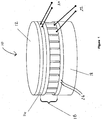
- a sensor device 10 comprises a surface 12 which is exposed to the surrounding environment.
- the sensor device 10 further comprises means 16 for cooling or heating the exposed surface 12.
- This is a bidirectional heat pump 16, for example a Peltier heat pump, and is electronically controlled by a controller (not shown) via heat pump wires 22.
- a heat sink 18 is provided for use with the heat pump 16, to dissipate heat into the surrounding air or aircraft structure.
- a temperature detector 14, forming part of, or situated just behind, the surface 12 outputs temperature readings indicative of the temperature of the surface 12 to an acquisition system (not shown) via temperature sense wires 20.
- the outer surface 12 may be formed of a material that provides physical protection to the sensor 10 and/or temperature detector 14, for example protection from abrasion.
- the outer surface 12 may be part of the sensor 10 or temperature detector 14, or may be a protective covering placed over the sensor 10 or temperature detector 14.
- a plurality of temperature detectors may be employed, providing a plurality of temperature readings, which may be averaged by the acquisition system.
- a second temperature detector 24 is optionally provided to monitor performance of the heat pump 16.
- a system for determining proximity to icing conditions comprises a sensor device 10 as shown in Figure 1 .
- a controller 50 is provided to electronically control the heat pump 16 via the heat pump wires 22 to heat or cool the exposed surface 12.
- the temperature readings from the temperature detector 14 are outputted to an acquisition system 60 via the temperature sense wires 20.
- a processing device 70 is provided to process the temperature readings from the acquisition system 60, and the results are outputted to an indicator 80 or other aircraft system.
- the controller 50 electronically controls the heat pump 16 to heat or cool the surface 12.
- the temperature detector 14 monitors a temperature that is indicative of that of surface 12 and the temperature sense wires 20 provide temperature readings to the acquisition system 60.
- the processing device 70 processes the temperature readings from the acquisition system 60 in a manner that will be described in more detail below, and provides the indicator 80 with information indicative of the likelihood of ice formation.
- the processing device 70 then instructs the controller 50 to heat or cool the surface as appropriate, to allow the measurement of the likelihood of ice formation to be repeated.
- the sensor device 10 When the air temperature is above that at which ice forms on the surface 12, the sensor device 10 is operable to predict how near the current flight conditions ("prevailing air conditions") are to the conditions in which ice is likely to form on the surface 12 ("surface icing conditions"). In this case, the controller 50 instructs the heat pump 16 to cool down the surface 12. Provided there is sufficient water content of the surrounding atmosphere, ice will eventually form on the cooled surface 12. The difference between the prevailing air temperature and the temperature at which ice forms on the surface 12 is a measure of the proximity to icing conditions. Alternatively the quantity of heat removed that causes icing to occur (i.e. the amount of cooling required to form ice), provides a qualitative measure of how near the prevailing air conditions are to surface icing conditions, i.e.
- the proximity to icing conditions determines whether the aircraft may be in danger from ice formation.
- the proximity to icing conditions determined from the sensor will provide the pilot with an indication that the aircraft may be in danger from ice formation. This is a significant improvement over a conventional ice detector, which can provide no indication of how close the aircraft is to icing conditions nor whether conditions are potentially suitable for the formation of ice, nor whether ice may already be forming on the aircraft but is not able to be detected.
- the sensor provides a positive determination that icing conditions exist or conditions that may be suitable for icing exist, irrespective of whether visible moisture is present or not.
- the controller 50 controls the heat pump 16 to heat the surface 12 up again.
- another measurement of the proximity to icing conditions is made by measuring the difference between the temperature indicative of that at which ice forms on the surface 12 and the prevailing air temperature, or by measuring the amount of heating required to melt the ice that has formed.
- the desired value e.g. the previous temperature of the surface before cooling and subsequent heating, or the ambient air temperature, or the maximum temperature that can be reached with maximum power to the heat pump or a defined temperature of operation
- the cooling process is started again and the process of determining icing proximity as described above is repeated. This enables the system to continually monitor and update the proximity to icing conditions and the icing severity.
- the controller 50 controls the heat pump 16 to heat the surface 12 and the amount of heating required to melt the ice that has formed gives a measure of the amount of ice that has formed. Cooling is still used however, to provide a more timely response and to give another measure of the amount of ice that has formed. This information can be useful to the pilot who can take action to bring the aircraft out of the icing conditions, or provide an input for triggering a de-icing system.
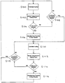
- Figure 3 is a flow chart showing the typical steps followed in the operation of the sensor device 10 as shown in Figure 1 , in the system of Figure 2 .
- step S100 with the surface 12 or air temperature above that at which ice would normally form on the surface 12, the surface 12 is cooled down by operation of the heat pump 16.
- This cooling is a controlled process and is performed for example with the heat pump 16 operating with a known or constant power, or to provide a known or constant rate of temperature decrease with time.
- the temperature of the surface 12 is monitored by the temperature detector 14 in step S102.
- the "cooling power" that is the amount of cooling required to reduce the temperature from the starting (e.g. ambient air temperature) to the temperature measured at that time, is also monitored, at step S102.
- Figure 4 shows the variation in temperature and power as a function of time, with the heat pump being controlled to attempt to cool at a constant temperature rate.
- the initial cooling follows the line of the graph at X in Figure 4 , which shows that when the temperature reaches that at which ice forms (0°C in the example shown) the temperature of the surface 12 typically increases slightly before flattening into a plateau. (This situation arises because the rate at which the water gives up its latent heat when freezing initially exceeds the controlled cooling rate of the heat pump.
- This region (region 'A'), between the point at which the temperature first reaches 0°C to when it again reaches 0°C, represents the removal of latent heat.
- the area/magnitude of region A provides an indication of the severity of icing conditions. Subsequently, the temperature continues to fall steadily as shown by the line of the graph at Y, with essentially the same gradient as before the icing point. It will be appreciated that ice will not necessarily start to form at 0°C, but may form at a different temperature depending on the local pressure, airflow and moisture content of the air. As shown in Figure 4 , if there is no moisture in the air, then no ice will form so the line of the graph will pass straight through 0°C to follow the line of the graph at Z.
- the processing device 70 uses this temperature information to determine the onset of ice formation.
- the proximity of the prevailing air conditions to surface icing conditions is calculated at step S106.
- the proximity to icing conditions has a value defined as the difference between a first temperature and the temperature indicative of ice formation.
- the first temperature may be a prevailing air temperature.
- the first temperature may be the temperature of the surface at the start of the cooling step.
- an "icing potential” is calculated. This is defined as the rate of change, and direction, of the icing proximity, and it provides an indication, or prediction, of the time to, or likelihood of, the aircraft experiencing icing conditions.
- step S104 of Figure 3 If the icing point is not detected at step S104 of Figure 3, i.e. if the temperature is not yet low enough for ice to form on the surface or if there is not enough moisture in the atmosphere, a determination is made instead as to whether a predetermined minimum temperature has been reached at step S108 (or a maximum power condition in which there is no further change in temperature while the heat pump continues to operate at maximum power). If that is not the case, the process returns to step S100, to continue cooling the surface 12.
- the surface is heated up again at step S110 at a known or substantially constant temperature (or known or substantially constant power) rate. Again the temperature of the surface 12 is monitored by temperature detector 14 at step S112.
- the "heating power” that is the amount of heating required to increase the temperature from the surface icing temperature or predetermined minimum temperature back up to the prevailing air temperature (or maximum desired or attainable temperature), is also monitored at step S112.
- step S116 If ice had previously formed on the surface 12, then during this heating of the surface 12 it will melt. This is equivalent to another icing point being detected, as latent heat is given to the ice to aid melting. Therefore if an icing point is detected during heating, another measurement of the icing proximity and icing potential is made at step S116.
- the temperature profile observed during heating is inverted relative to the one observed during cooling and is shown in Figure 5B .
- the quantity of heat provided gives an indication of the quantity of ice previously formed and which is now being removed. However, it should be borne in mind that during heating it is possible that once a small layer of ice adjacent the heat pump surface 12 has melted, the ice on top of this may simply be blown away.
- the quantity of heat provided may not be a reliable indicator, unless only a small amount of ice is allowed to form, or the measured values are compensated to allow for this effect.
- the cooling process at step S100 is started again. If the maximum temperature has not yet been reached at step S118 then the heating process at step S110 continues until either an icing point is detected at step S114 or the maximum temperature is reached at step S118.
- a maximum preset value e.g. the temperature prior to cooling or the ambient air temperature or a defined maximum temperature
- the heating process at step S110 continues until either an icing point is detected at step S114 or the maximum temperature is reached at step S118.
- Figure 4 also shows the variation in power with time, whilst attempting constant temperature rate cooling.
- a rapid increase in cooling power is required (or a rapid increase of heater power if the ambient temperature is below 0°C). This occurs with no overall significant change in temperature.
- This increase in power is representative of the onset of icing conditions and hence gives an indication of the icing proximity and icing potential.
- the magnitude of the increase could also be used to provide a measure of the icing severity in an analogous manner to that described above for when the surface is being cooled.
- Figure 5A shows the variation in temperature and power with time, with the cooling performed at a known or substantially constant power (compared with attempting the constant temperature rate cooling of Figure 4 ). A similar increase and plateau in the temperature curve are again observed as latent heat is released as ice starts to form.
- the icing proximity and icing potential are determined in a manner similar to that described above for the constant temperature rate cooling.
- the magnitude of the temperature rise 'H2', or the area B - are representative of the release of latent heat, and can be used to provide a measurement of the icing severity.
- the sensor device 10 also operates as a conventional ice detector, if ice has already formed on the surface 12 being monitored. If the surface is heated to melt the ice, latent heat will be required for the phase change, providing a detectable temperature reversal and/or plateau.
- Figure 5B shows the variation in temperature with time for the case where the surface is being heated at a known or substantially constant power, with the temperature reversal shown as H3 and the area under the plateau curve as C. The characteristics of this temperature reversal or plateau provide a measurement of the icing severity as described above.
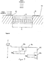
- the sensor device 10 of Figure 1 is shown embedded in an aircraft surface 90.
- the exterior surface 12 of the sensor device 10 is preferably level and flush with the exterior aircraft surface 90 in which it is embedded.
- the aircraft surface 90 is typically an aircraft wing or skin or engine nacelle, or part of a new strut or fin provided for the purpose of ice detection and prediction.
- the device 10 could be mounted such that the exterior surface 12 is proud of or recessed in to the aircraft surface 90.
- the device could also form part of a structure mounted to the aircraft.
- the device 10 could be incorporated into a housing with a flow passage through which air may be induced to flow (for example using bleed air from the aircraft engine system).
- a sensor of this type may be particularly useful at low air speeds or where the aircraft (e.g. a helicopter) is hovering.
- the device 10 could be incorporated into a housing that is moving or rotating as part of a new or existing aircraft system, such that air flow over the device 10 is maintained or created to allow detection at low air speeds or when hovering (e.g. the device is mounted to a rotating part of the rotor head or blades of a helicopter, such as the power distribution section of a rotor ice protection system)
- the positioning of the sensor device 10 relative to the air flow around the aircraft is important to the effectiveness of the prediction/detection system.
- the orientation of the sensor device 10 to the airflow determines the conditions being detected. If the sensor device 10 is mounted on the leading edge of the aircraft structure, air flows in the direction 'A' and so the sensor senses the conditions at the air stagnation point, which is typically at a higher temperature than ambient. The leading edge may be flat or curved. If the sensor device 10 is mounted with air flow direction 'B', the conditions sensed are that within the airflow boundary layer, inside an area of laminar flow. In this case, the sensor device 10 is mounted on the flat surface of a horizontal (e.g.
- the device 10 may also be positioned on a surface at any orientation between the substantially vertical and horizontal positions shown in Figure 6 .
- a suitable orientation and mounting location may be based on the ice build-up characteristics of the aircraft surface, which may depend on the local surface characteristics and aerodynamics, to aid moisture capture and to aid ice or moisture shedding from the sensor surface.
- two or more sensor detectors 10 are used, located -at positions determined for optimal performance.
- a heater 92 may be provided on the aircraft surface 90 in proximity to the device surface 12.
- the heater is shown mounted close to, but not contacting the surface 12. The separation of the heater from the device is selected so that heat conduction from the heater into the sensor does not interfere with operation or accuracy of the device 10.
- a region of thermal insulation (not shown) may be provided between the heater 92 and the sensor surface 12. Heater 92 and local surface 90 may be provided as part of the assembly including the sensor 10.
- the ice detector systems as described above have significant advantages over traditional ice detection systems by providing information to an aircraft pilot about the proximity to icing conditions as the aircraft flies through varying environmental conditions. This is particularly important because the conditions may cause ice to form at certain surface locations on the aircraft without ice being formed at the specific location of a traditional sensor, which the sensor and consequently the pilot would be unaware of. However, as explained above, positioning of the sensor is important because different local environmental conditions can arise at different surface locations such as due to local variations in pressure.
- Figure 7 illustrates an ice detection system for surfaces 94, 95, which are being caused to rotate about an axis X-X.
- Two sensors 96a, 96b are shown by way of example, each mounted to one of the rotating surfaces 94, 95.
- the surface 94 might be a horizontal surface of part of a helicopter rotor assembly, while the surface 95 might be a radially outward facing surface of the rotor assembly.
- the principles described below may be applied to a system having just one sensor or many sensors.
- the sensors 96a, 96b have respective exposed surfaces 97a, 97b and in the illustrated embodiment are mounted with the surfaces 97a, 97b flush with the rotating surfaces 94, 95. Alternatively, the sensors could be mounted such that the exposed surfaces 97a, 97b stand proud of the surfaces 94, 95, or are recessed below the rotating surfaces 94, 95.
- the sensors 96a, 96b may be mounted to present the exposed surfaces 97a, 97b at an angle to the direction of movement so that the rotational movement presents an incident "air flow".
- the sensor surfaces 97a, 97b may be angled at any angle between being parallel with the air flow and being perpendicular to the air flow. The angle may be selected to optimise the sensing efficiency without causing excessive drag.
- the surfaces 94, 95 may be angled to present the sensors 96a, 96b and the exposed surfaces 97a, 97b at an angle to the direction of movement so that the rotational movement presents an incident "air flow".
- the surfaces 94, 95 may be angled at any angle between being parallel with the air flow and being perpendicular to the air flow. The angle may be selected to optimise the sensing efficiency without causing excessive drag.
- the sensors 96a, 96b each include a temperature detector, such as a thermocouple or resistance thermometer, that determines a temperature of the rotating exposed surface 97a, 97b.
- the sensors 96a 96b each provide a signal at a respective output 98a, 98b.
- the sensors 96a, 96b may also include one or more further temperature detectors that monitor a temperature of an environment through which the surface rotates. Alternatively separate sensors may be used to determine the local environment temperature, or this may be provided by other system components.
- the temperature values surface and environment are provided to a processor that determines a proximity to or presence of icing conditions, in a manner similar to that described above.
- the processor may form part of each sensor 96a, 96b in which case a signal is provided at the respective output 98a, 98b to indicate presence of, or a proximity to icing conditions at the respective rotating exposed surface 97a, 97b.
- the processing may be performed elsewhere (for example at a central processor, which may or may not be rotating with the sensors 96a, 96b).
- the ice detector system may include any or all of the features of the detector systems described above with reference to figures 1 to 6 .
- ice detection systems such as on wind turbines, wind turbine blades, in an air inlet for an engine such as a power generator jet turbine, on an unmanned aerial vehicle or any other application where the presence of or proximity to icing conditions would be beneficial.
- the device and processing means can also be used as described to determine the humidity level or moisture content of the environment.
Landscapes
- Physics & Mathematics (AREA)
- Health & Medical Sciences (AREA)
- Life Sciences & Earth Sciences (AREA)
- Chemical & Material Sciences (AREA)
- Analytical Chemistry (AREA)
- Biochemistry (AREA)
- General Health & Medical Sciences (AREA)
- General Physics & Mathematics (AREA)
- Immunology (AREA)
- Pathology (AREA)
- Engineering & Computer Science (AREA)
- Aviation & Aerospace Engineering (AREA)
- Testing Or Calibration Of Command Recording Devices (AREA)
- Investigating Or Analyzing Materials Using Thermal Means (AREA)
Claims (22)
- Verfahren zum Feststellen der Annäherung an Vereisungsbedingungen in einer Umgebung, umfassend die Schritte:Bereitstellen eines Sensors (10), welcher eine der Umgebung ausgesetzten Fläche (12) und ein Wärmepumpmittel (16) zum Erwärmen und/oder Kühlen der Fläche aufweist;Betreiben der Wärmepumpe (16), um die Fläche zu kühlen oder erwärmen;Überwachen einer Flächentemperatur;Feststellen einer Temperatur, welche die Eisbildung anzeigt;Feststellen einer Umgebungstemperatur, welche die Temperatur der Umgebung darstellt, welcher die Sensorfläche ausgesetzt ist; undFeststellen des Werts einer Differenz zwischen der Umgebungstemperatur und der Temperatur, welche die Eisbildung anzeigt, wobei der Wert eine Annäherung an Vereisungsbedingungen der Umgebung darstellt, welcher die Fläche (12) ausgesetzt ist.
- Verfahren nach Anspruch 1, wobei die Umgebungstemperatur eine vorherrschende Lufttemperatur ist.
- Verfahren nach Anspruch 2, wobei die Umgebungstemperatur aus einer Temperatur der Fläche (12) abgeleitet wird, wenn nicht gekühlt oder erwärmt wird, oder von einem unabhängigen Temperatursensor festgestellt wird.
- Verfahren nach Anspruch 3, ferner umfassend
Feststellen einer Leistung, welche zum Erwärmen oder Kühlen der Fläche (12), bis auf oder ausgehend von der festgestellten Umgebungstemperatur, benötigt wird, durch die Temperatur, welche die Eisbildung anzeigt; und
Feststellen, auf Grund der überwachten Temperaturen und der Wärmeleistung oder der Kühlleistung, eines Werts einer abgeführten Wärmemenge, welche die Vereisung verursacht, oder einer Wärmemenge, welche benötigt wird, um das gebildete Eis zu schmelzen, wobei der Wert ein alternatives, qualitatives Maß der Annäherung an Vereisungsbedingungen der Umgebung darstellt, welcher die Fläche (12) ausgesetzt ist. - Verfahren nach einem der Ansprüche 1 bis 4, ferner umfassend das Feststellen einer Zeitangabe oder einer Wahrscheinlichkeitsangabe bezüglich der Entstehung von Vereisungsbedingungen.
- Verfahren nach Anspruch 5, wobei das Potential einer Vereisung durch Messung der Änderungsrate und der Richtung der Annäherung an Vereisungsbedingungen bestimmt wird.
- Verfahren nach einem der Ansprüche 1 bis 6, wobei das Kühlen oder Erwärmen der Fläche (12) mit einer bekannten oder im Wesentlichen konstanten Leistung durchgeführt wird.
- Verfahren nach einem der Ansprüche 1 bis 7, wobei die Temperatur, welche die Vereisung angibt, durch Messen der Änderung der Temperatur mit der Zeit und Erfassen eines Plateaus (A; B; C) oder Richtungsänderung in der Änderung der Temperatur mit der Zeit festgestellt wird, welche sich aus der latenten Wärme der Eisbildung ergibt.
- Verfahren nach einem der Ansprüche 1 bis 6, wobei der Schritt des Kühlens oder des Erwärmens der Fläche (12) das Steuern des Kühlens oder des Erwärmens umfasst, um eine im Wesentlichen konstante Temperaturänderungsrate pro Zeiteinheit zu erhalten.
- Verfahren nach Anspruch 9, wobei die Temperatur, welche die Eisbildung anzeigt, durch Überwachen der Kühl- oder Wärmeleistung mit der Zeit festgestellt wird, um die Temperatur zu erfassen, bei welcher eine Leistungsänderung stattfindet, welche durch die latente Wärme der Eisbildung bedingt ist.
- Verfahren nach einem der Ansprüche 1 bis 10, umfassend das abwechselnde Kühlen und Erwärmen der Fläche (12).
- Verfahren nach Anspruch 11, wobei die Annäherung an Vereisungsbedingungen sowohl bei Erwärmung als auch bei Kühlung der Fläche (12) festgestellt wird.
- Verfahren nach Anspruch 11 oder Anspruch 12, umfassend das kontinuierliche Wiederholen des abwechselnden Erwärmens und Kühlens.
- Verfahren nach einem der Ansprüche 1 bis 13, ferner umfassend das Feststellen der Schwere der Vereisung.
- Verfahren nach Anspruch 14, wobei das Feststellen der Schwere der Vereisung das Messen der Größe der Erhöhung der Temperatur (H1; H2) oder Dauer eines Temperaturplateaus (A; B), wenn die Eisbildung während des Kühlens stattfindet, oder das Messen der Größe einer Reduzierung der Temperatur (H3) oder Dauer eines Temperaturplateaus (C) umfasst, wenn die Eisbildung während des Erwärmens stattfindet.
- Sensorsystem zum Feststellen einer Annäherung an Vereisungsbedingungen einer Umgebung, wobei das System umfasst:einen Sensor (10), welcher eine Sensorfläche (12) aufweist, welche einer Umgebung ausgesetzt ist, ein elektrisch angetriebenes Wärmepumpmittel (16) zum Kühlen und/oder Erwärmen der Fläche, und einen Temperaturdetektor (14) zum Bereitstellen eines Signals, welches die Temperatur der Fläche (12) darstellt;Mittel zum Festellen einer Temperatur, welche die Eisbildung anzeigt;Mittel zum Festellen einer Umgebungstemperatur, welche die Temperatur der Umgebung darstellt, welcher die Sensorfläche ausgesetzt ist;undeinen Prozessor (70), welcher konfiguriert ist, um eine Annäherung an Vereisungsbedingungen der Umgebung, welcher die Fläche ausgesetzt ist, festzustellen, mit einem Verfahren nach einem der Ansprüche 1 bis 15.
- Sensorsystem nach Anspruch 16, wobei die Wärmepumpe (16) eine bidirektionale Wärmepumpe ist, zum Beispiel eine Peltier-Wärmepumpe.
- Sensorsystem nach Anspruch 16 oder 17, welches zum Verwenden auf einem Flugzeug konfiguriert ist, wobei die Sensorfläche (12) mit einer Fläche des Flugzeugs (90), wie zum Beispiel der Flugzeughaut, einem Flügel oder einer Triebwerksgondel, fluchtet, oder wobei die Sensorfläche (12) aus einer Oberfläche herausragt oder in einer Oberfläche des Flugzeugs (90) eingelassen ist, oder wobei die Sensorfläche (12) Teil einer Struktur ist, welche auf dem Flugzeug getragen ist, wie zum Beispiel ein abstehender Träger, oder eine Strebe oder Seitenflosse des Flugzeugs.
- Sensorsystem nach Anspruch 18, wobei die Sensorfläche (12) im Wesentlichen parallel zur Richtung ("B") der Luftströmung über dem Flugzeug liegt, oder wobei die Sensorfläche im Wesentlichen senkrecht zur Richtung der Luftströmung ("A") über dem Flugzeug liegt, oder wobei die Sensorfläche um einen Winkel zur Richtung der Luftströmung über dem Flugzeug geneigt ist.
- Sensorsystem nach einem der Ansprüche 16 bis 19, umfassend eine Mehrzahl von Sensoren (10), welche jeweils eine Fläche (12) aufweisen, welche der Umgebung ausgesetzt ist, wobei der Prozessor (70) die Annäherung an Vereisungsbedingungen auf Grund der erfassten Temperaturen und optional der jedem der Mehrzahl von Sensoren (10) bereitgestellten Kühlleistung oder Wärmeleistung, feststellt.
- Sensorsystem nach einem der Ansprüche 16 bis 20, welches Teil eines Eisnachweissystems ist, umfassend
eine rotierende Fläche (94; 95), wobei
der Sensor (96a; 96b) ein erster auf einer rotierenden Fläche (94; 95) gehalterter Sensor ist, und die Mittel zum Feststellen einer Umgebungstemperatur
einen zweiten Sensor umfassen, um die Temperatur der Umgebung festzustellen, in der die Fläche rotiert. - Sensorsystem nach Anspruch 21, wobei die rotierende Fläche (94; 95) eine Oberfläche eines Rotors, einer Rotoranordnung, eines Propellers oder einer Turbinenschaufel ist.
Applications Claiming Priority (2)
| Application Number | Priority Date | Filing Date | Title |
|---|---|---|---|
| GBGB0823121.9A GB0823121D0 (en) | 2008-12-18 | 2008-12-18 | Ice detection system |
| PCT/GB2009/002881 WO2010070273A1 (en) | 2008-12-18 | 2009-12-16 | Icing sensor system and method |
Publications (2)
| Publication Number | Publication Date |
|---|---|
| EP2389314A1 EP2389314A1 (de) | 2011-11-30 |
| EP2389314B1 true EP2389314B1 (de) | 2016-06-22 |
Family
ID=40343840
Family Applications (1)
| Application Number | Title | Priority Date | Filing Date |
|---|---|---|---|
| EP09804140.3A Not-in-force EP2389314B1 (de) | 2008-12-18 | 2009-12-16 | Vereisungssensorsystem und verfahren |
Country Status (7)
| Country | Link |
|---|---|
| US (1) | US9156557B2 (de) |
| EP (1) | EP2389314B1 (de) |
| CN (1) | CN102438903A (de) |
| CA (1) | CA2747268A1 (de) |
| GB (1) | GB0823121D0 (de) |
| RU (1) | RU2534493C2 (de) |
| WO (1) | WO2010070273A1 (de) |
Cited By (1)
| Publication number | Priority date | Publication date | Assignee | Title |
|---|---|---|---|---|
| GB2554062A (en) * | 2016-08-22 | 2018-03-28 | Norwegian Univ Of Science And Technology | Icing control system |
Families Citing this family (37)
| Publication number | Priority date | Publication date | Assignee | Title |
|---|---|---|---|---|
| FR2914906B1 (fr) * | 2007-04-11 | 2009-10-30 | Intertechnique Soc Par Actions | Procede et dispositif de detection de givre et /ou conditions givrantes sur aeronef en vol |
| GB0823121D0 (en) | 2008-12-18 | 2009-01-28 | Penny & Giles Controls Ltd | Ice detection system |
| US8517601B2 (en) * | 2010-09-10 | 2013-08-27 | Ultra Electronics Limited | Ice detection system and method |
| US9429076B2 (en) | 2011-01-11 | 2016-08-30 | Bae Systems Plc | Turboprop-powered aircraft with thermal system |
| AU2012206414A1 (en) | 2011-01-11 | 2013-08-01 | Bae Systems Plc | Turboprop-powered aircraft |
| RU2507125C2 (ru) * | 2012-05-23 | 2014-02-20 | Олег Петрович Ильин | Сигнализатор обледенения лопастей несущего винта вертолета |
| CN102830445B (zh) * | 2012-09-06 | 2015-07-01 | 中国气象局气象探测中心 | 一种地面气象观测中结冰自动化观测方法及装置 |
| CN102855792A (zh) * | 2012-09-14 | 2013-01-02 | 江苏苏威尔科技有限公司 | 一种水凝固与冰熔化的实验器及其实验方法 |
| US10179652B2 (en) * | 2013-07-29 | 2019-01-15 | Surewx Inc. | Active frost forecasting, detection and warning system and method |
| US9612163B2 (en) * | 2013-10-10 | 2017-04-04 | The Boeing Company | Methods and apparatus for detecting ice formation on aircraft |
| CA3012392C (en) | 2015-03-12 | 2021-04-27 | Universite Laval | System and method for determining an icing condition status of an environment |
| US10214294B1 (en) * | 2015-08-21 | 2019-02-26 | Blue Storm Associates, Inc. | Method and system for predicting potential icing conditions |
| CN105083559A (zh) * | 2015-09-21 | 2015-11-25 | 成都乐也科技有限公司 | 一种检测飞机表面结冰情况的温度探测器 |
| WO2017138846A1 (ru) * | 2016-02-10 | 2017-08-17 | Геннадий Гюсамович ГРОМОВ | Термоэлектрический датчик обледенения |
| US10392117B2 (en) * | 2016-09-23 | 2019-08-27 | General Electric Company | Icing condition detection using instantaneous humidity sensing |
| FR3066007B1 (fr) * | 2017-05-05 | 2020-10-02 | Gaztransport Et Technigaz | Installation de stockage pour un gaz liquefie |
| EP3413039B1 (de) | 2017-06-07 | 2020-12-23 | Belimed AG | Vorrichtung zur bestimmung des taupunktes eines gases in einem prozessraum und wärmebehandlungsvorrichtung mit einer solchen vorrichtung zur bestimmung des taupunktes |
| CN110730865B (zh) * | 2017-06-16 | 2021-06-22 | 维斯塔斯风力系统集团公司 | 用于确定风力涡轮机中的结冰风险的装置和方法 |
| CA3066697A1 (en) | 2017-06-29 | 2019-01-03 | Vestas Wind Systems A/S | Detecting water on a wind turbine using a temperature-controlled sensor |
| CN107389433B (zh) * | 2017-09-14 | 2023-06-27 | 国家电网公司 | 一种用于检测水库结冰对水利建筑冰推力以及冰拔破坏的检测箱及其检测方法 |
| CN108820227B (zh) * | 2018-07-03 | 2021-12-03 | 上海工程技术大学 | 一种利用石墨烯加热膜的预测型防除冰的方法 |
| RU2685631C1 (ru) * | 2018-07-11 | 2019-04-22 | Бараусов Виктор Александрович | Способ и устройство обнаружения обледенения или снега на контролируемой поверхности |
| CN109573057B (zh) * | 2018-11-24 | 2021-02-23 | 中国人民解放军空军工程大学 | 一种基于等离子体的物面积冰传感器的使用方法 |
| US11459112B2 (en) | 2019-07-19 | 2022-10-04 | Rosemount Aerospace Inc. | Active aircraft probe heat monitor and method of use |
| CN111595386A (zh) * | 2020-06-12 | 2020-08-28 | 中国民航大学 | 一种跑道积冰自主感知装置 |
| US12103690B2 (en) | 2020-11-05 | 2024-10-01 | United States Of America As Represented By The Secretary Of The Air Force | Ice detection and precautionary system shut-down event reduction systems and related methods |
| DE102021112581B4 (de) * | 2021-05-14 | 2023-11-30 | 3P Instruments GmbH & Co. KG | Vorrichtung zum Temperieren einer Messzelle und Verfahren zum Betreiben der Vorrichtung |
| RU2767246C1 (ru) * | 2021-08-04 | 2022-03-18 | Виктор Александрович Бараусов | Модуль периодического определения наледи на длинномерных элементах конструкций, в частности проводах воздушных лэп |
| CN113669882B (zh) * | 2021-09-10 | 2024-12-06 | 珠海格力电器股份有限公司 | 检冰装置、化冰系统及空调器 |
| US11926425B2 (en) | 2021-11-30 | 2024-03-12 | Goodrich Corporation | Adjustable ice protection system parting strip |
| CN114322423B (zh) * | 2021-12-09 | 2022-10-28 | 西安交通大学 | 一种冷表面结霜量测量装置及应用 |
| RU2779247C1 (ru) * | 2021-12-16 | 2022-09-05 | Общество С Ограниченной Ответственностью "Микролаб" | Способ определения температуры фазового перехода и объема пробы жидкости с помощью термоэлектрического датчика обледенения |
| CN114487101B (zh) * | 2021-12-31 | 2023-06-16 | 中国民航大学 | 冰点检测及积冰预警装置及方法 |
| CN116087264B (zh) * | 2022-09-30 | 2025-06-17 | 西北工业大学 | 一种基于柔性热敏式传感器的物体表面结冰检测方法 |
| US20240327005A1 (en) * | 2023-03-28 | 2024-10-03 | Rosemount Aerospace Inc. | Air data sensor strut ice protection |
| WO2025048682A1 (ru) * | 2023-08-25 | 2025-03-06 | Общество С Ограниченной Ответственностью "Микролаб" | Способы определения температуры кристаллизации и объема пробы водно-солевых растворов |
| WO2025080165A1 (ru) * | 2023-10-09 | 2025-04-17 | Общество С Ограниченной Ответственностью "Микролаб" | Способ определения объема пробы водно-солевых растворов |
Family Cites Families (33)
| Publication number | Priority date | Publication date | Assignee | Title |
|---|---|---|---|---|
| US3276254A (en) * | 1963-10-11 | 1966-10-04 | Rosemount Eng Co Ltd | Ice detection apparatus |
| US3305851A (en) * | 1964-09-03 | 1967-02-21 | Solid State Engineering Co | Icing condition detection apparatus |
| US4054255A (en) * | 1976-04-01 | 1977-10-18 | System Development Corporation | Microwave ice detector |
| US4329682A (en) * | 1976-05-03 | 1982-05-11 | Hawker Siddeley Dynamics Ltd. | Phase change warning devices |
| CH656015A5 (en) * | 1984-02-27 | 1986-05-30 | Vibro Meter Ag | Method of detecting a risk of freezing, warning device for implementing the method and its use |
| US4980673A (en) | 1987-06-10 | 1990-12-25 | Rosemount Inc. | Ice detector circuit |
| RU2078716C1 (ru) * | 1992-05-26 | 1997-05-10 | Главная геофизическая обсерватория им.А.И.Воейкова | Устройство обнаружения и измерения интенсивности обледенения летательного аппарата |
| US5521584A (en) * | 1993-10-13 | 1996-05-28 | Eaton Corporation | Apparatus and method for detecting ice |
| SE501810C2 (sv) * | 1993-10-15 | 1995-05-22 | Agenzia International Ab | Anordning för indikering av isbildning |
| US5523959A (en) * | 1994-04-25 | 1996-06-04 | The United States Of America As Represented By The Administrator Of The National Aeronautics And Space Administration | Ice detector and deicing fluid effectiveness monitoring system |
| US5709470A (en) * | 1995-07-10 | 1998-01-20 | Cnc Development, Inc. | Method and apparatus for detecting ice buildup |
| US6126311A (en) * | 1998-11-02 | 2000-10-03 | Claud S. Gordon Company | Dew point sensor using mems |
| US6328467B1 (en) * | 1999-05-07 | 2001-12-11 | University Of Tennessee Research Corp. | Method and apparatus for detecting ice or frost deposition |
| AU2003213017A1 (en) | 2002-02-11 | 2003-09-04 | The Trustees Of Dartmouth College | Systems and methods for modifying an ice-to-object interface |
| US20090235681A1 (en) | 2002-02-11 | 2009-09-24 | The Trustees Of Dartmouth College | Pulse Electrothermal Mold Release Icemaker For Refrigerator Having Interlock Closure And Baffle For Safety |
| US8921739B2 (en) | 2002-02-11 | 2014-12-30 | The Trustees Of Dartmouth College | Systems and methods for windshield deicing |
| US7570760B1 (en) | 2004-09-13 | 2009-08-04 | Sun Microsystems, Inc. | Apparatus and method for implementing a block cipher algorithm |
| RU2289892C2 (ru) | 2002-02-11 | 2006-12-20 | Дзе Трастриз Оф Дартмут Колледж | Системы и способы изменения границы раздела между льдом и объектом |
| US20080223842A1 (en) | 2002-02-11 | 2008-09-18 | The Trustees Of Dartmouth College | Systems And Methods For Windshield Deicing |
| US20080196429A1 (en) | 2002-02-11 | 2008-08-21 | The Trustees Of Dartmouth College | Pulse Electrothermal And Heat-Storage Ice Detachment Apparatus And Method |
| US7638735B2 (en) | 2002-02-11 | 2009-12-29 | The Trustees Of Dartmouth College | Pulse electrothermal and heat-storage ice detachment apparatus and methods |
| US8405002B2 (en) | 2002-02-11 | 2013-03-26 | The Trustees Of Dartmouth College | Pulse electrothermal mold release icemaker with safety baffles for refrigerator |
| US7014357B2 (en) * | 2002-11-19 | 2006-03-21 | Rosemount Aerospace Inc. | Thermal icing conditions detector |
| US7175136B2 (en) * | 2003-04-16 | 2007-02-13 | The Boeing Company | Method and apparatus for detecting conditions conducive to ice formation |
| EP1696998B1 (de) * | 2003-11-07 | 2017-01-11 | CardioLa Ltd. | Zähler-pulsationselektrotherapiegerät zur behandlung einer person oder eines säugetiers |
| FR2858595B1 (fr) | 2003-11-18 | 2005-10-14 | Auxitrol Sa | Ensemble de detection de givre destine a etre monte sur aeronef |
| US7703300B2 (en) | 2004-06-22 | 2010-04-27 | The Trustees Of Dartmouth College | Pulse systems and methods for detaching ice |
| EP2032916A2 (de) | 2006-05-22 | 2009-03-11 | The Trustees of Dartmouth College | Enteisung komplexer formen durch elektrothermale impulse |
| ITTO20060400A1 (it) | 2006-05-31 | 2007-12-01 | Lorenzo Battisti | Metodo e sistema per la rilevazione di pericolo di formazione di ghiaccio su superfici aerodinamiche |
| RU2323131C1 (ru) * | 2006-07-05 | 2008-04-27 | Александр Михайлович Павельев | Способ контроля обледенения и устройство для его осуществления |
| FR2914906B1 (fr) | 2007-04-11 | 2009-10-30 | Intertechnique Soc Par Actions | Procede et dispositif de detection de givre et /ou conditions givrantes sur aeronef en vol |
| US20080257033A1 (en) * | 2007-04-20 | 2008-10-23 | Shadin, L.P. | Ice detection |
| GB0823121D0 (en) | 2008-12-18 | 2009-01-28 | Penny & Giles Controls Ltd | Ice detection system |
-
2008
- 2008-12-18 GB GBGB0823121.9A patent/GB0823121D0/en active Pending
-
2009
- 2009-12-16 CA CA2747268A patent/CA2747268A1/en not_active Abandoned
- 2009-12-16 RU RU2011129689/11A patent/RU2534493C2/ru not_active IP Right Cessation
- 2009-12-16 US US13/140,802 patent/US9156557B2/en not_active Expired - Fee Related
- 2009-12-16 EP EP09804140.3A patent/EP2389314B1/de not_active Not-in-force
- 2009-12-16 WO PCT/GB2009/002881 patent/WO2010070273A1/en not_active Ceased
- 2009-12-16 CN CN2009801569892A patent/CN102438903A/zh active Pending
Cited By (1)
| Publication number | Priority date | Publication date | Assignee | Title |
|---|---|---|---|---|
| GB2554062A (en) * | 2016-08-22 | 2018-03-28 | Norwegian Univ Of Science And Technology | Icing control system |
Also Published As
| Publication number | Publication date |
|---|---|
| CN102438903A (zh) | 2012-05-02 |
| EP2389314A1 (de) | 2011-11-30 |
| GB0823121D0 (en) | 2009-01-28 |
| WO2010070273A1 (en) | 2010-06-24 |
| US9156557B2 (en) | 2015-10-13 |
| US20120099616A1 (en) | 2012-04-26 |
| RU2534493C2 (ru) | 2014-11-27 |
| CA2747268A1 (en) | 2010-06-24 |
| RU2011129689A (ru) | 2013-01-27 |
Similar Documents
| Publication | Publication Date | Title |
|---|---|---|
| EP2389314B1 (de) | Vereisungssensorsystem und verfahren | |
| US9676485B2 (en) | Ice detection system and method | |
| US10018580B2 (en) | Apparatus and method for detecting water or ice | |
| US20120266669A1 (en) | Sensor Arrangement | |
| CN102407942B (zh) | 结冰条件探测器 | |
| US11242152B2 (en) | Method and apparatus for detecting ice accretion | |
| US20220411079A1 (en) | Apparatus and method for detecting water or ice | |
| US8602361B2 (en) | Laminar flow monitor | |
| EP4186796B1 (de) | Trennstreifen für einstellbares eisschutzsystem | |
| US11390387B2 (en) | De-icing system and method | |
| RU162213U1 (ru) | Термоэлектрический датчик обледенения | |
| HK40042013A (en) | Apparatus and method for detecting water or ice |
Legal Events
| Date | Code | Title | Description |
|---|---|---|---|
| PUAI | Public reference made under article 153(3) epc to a published international application that has entered the european phase |
Free format text: ORIGINAL CODE: 0009012 |
|
| 17P | Request for examination filed |
Effective date: 20110708 |
|
| AK | Designated contracting states |
Kind code of ref document: A1 Designated state(s): AT BE BG CH CY CZ DE DK EE ES FI FR GB GR HR HU IE IS IT LI LT LU LV MC MK MT NL NO PL PT RO SE SI SK SM TR |
|
| DAX | Request for extension of the european patent (deleted) | ||
| 17Q | First examination report despatched |
Effective date: 20131108 |
|
| REG | Reference to a national code |
Ref country code: DE Ref legal event code: R079 Ref document number: 602009039373 Country of ref document: DE Free format text: PREVIOUS MAIN CLASS: B64D0015200000 Ipc: G01N0025680000 |
|
| GRAP | Despatch of communication of intention to grant a patent |
Free format text: ORIGINAL CODE: EPIDOSNIGR1 |
|
| RIC1 | Information provided on ipc code assigned before grant |
Ipc: G01N 25/68 20060101AFI20151106BHEP |
|
| INTG | Intention to grant announced |
Effective date: 20151130 |
|
| GRAS | Grant fee paid |
Free format text: ORIGINAL CODE: EPIDOSNIGR3 |
|
| GRAA | (expected) grant |
Free format text: ORIGINAL CODE: 0009210 |
|
| AK | Designated contracting states |
Kind code of ref document: B1 Designated state(s): AT BE BG CH CY CZ DE DK EE ES FI FR GB GR HR HU IE IS IT LI LT LU LV MC MK MT NL NO PL PT RO SE SI SK SM TR |
|
| REG | Reference to a national code |
Ref country code: GB Ref legal event code: FG4D |
|
| REG | Reference to a national code |
Ref country code: CH Ref legal event code: EP |
|
| REG | Reference to a national code |
Ref country code: IE Ref legal event code: FG4D |
|
| REG | Reference to a national code |
Ref country code: AT Ref legal event code: REF Ref document number: 807949 Country of ref document: AT Kind code of ref document: T Effective date: 20160715 |
|
| REG | Reference to a national code |
Ref country code: DE Ref legal event code: R096 Ref document number: 602009039373 Country of ref document: DE |
|
| REG | Reference to a national code |
Ref country code: LT Ref legal event code: MG4D |
|
| REG | Reference to a national code |
Ref country code: NL Ref legal event code: MP Effective date: 20160622 |
|
| PG25 | Lapsed in a contracting state [announced via postgrant information from national office to epo] |
Ref country code: NO Free format text: LAPSE BECAUSE OF FAILURE TO SUBMIT A TRANSLATION OF THE DESCRIPTION OR TO PAY THE FEE WITHIN THE PRESCRIBED TIME-LIMIT Effective date: 20160922 Ref country code: LT Free format text: LAPSE BECAUSE OF FAILURE TO SUBMIT A TRANSLATION OF THE DESCRIPTION OR TO PAY THE FEE WITHIN THE PRESCRIBED TIME-LIMIT Effective date: 20160622 Ref country code: FI Free format text: LAPSE BECAUSE OF FAILURE TO SUBMIT A TRANSLATION OF THE DESCRIPTION OR TO PAY THE FEE WITHIN THE PRESCRIBED TIME-LIMIT Effective date: 20160622 |
|
| REG | Reference to a national code |
Ref country code: AT Ref legal event code: MK05 Ref document number: 807949 Country of ref document: AT Kind code of ref document: T Effective date: 20160622 |
|
| PG25 | Lapsed in a contracting state [announced via postgrant information from national office to epo] |
Ref country code: LV Free format text: LAPSE BECAUSE OF FAILURE TO SUBMIT A TRANSLATION OF THE DESCRIPTION OR TO PAY THE FEE WITHIN THE PRESCRIBED TIME-LIMIT Effective date: 20160622 Ref country code: NL Free format text: LAPSE BECAUSE OF FAILURE TO SUBMIT A TRANSLATION OF THE DESCRIPTION OR TO PAY THE FEE WITHIN THE PRESCRIBED TIME-LIMIT Effective date: 20160622 Ref country code: GR Free format text: LAPSE BECAUSE OF FAILURE TO SUBMIT A TRANSLATION OF THE DESCRIPTION OR TO PAY THE FEE WITHIN THE PRESCRIBED TIME-LIMIT Effective date: 20160923 Ref country code: SE Free format text: LAPSE BECAUSE OF FAILURE TO SUBMIT A TRANSLATION OF THE DESCRIPTION OR TO PAY THE FEE WITHIN THE PRESCRIBED TIME-LIMIT Effective date: 20160622 Ref country code: HR Free format text: LAPSE BECAUSE OF FAILURE TO SUBMIT A TRANSLATION OF THE DESCRIPTION OR TO PAY THE FEE WITHIN THE PRESCRIBED TIME-LIMIT Effective date: 20160622 |
|
| PG25 | Lapsed in a contracting state [announced via postgrant information from national office to epo] |
Ref country code: RO Free format text: LAPSE BECAUSE OF FAILURE TO SUBMIT A TRANSLATION OF THE DESCRIPTION OR TO PAY THE FEE WITHIN THE PRESCRIBED TIME-LIMIT Effective date: 20160622 Ref country code: IS Free format text: LAPSE BECAUSE OF FAILURE TO SUBMIT A TRANSLATION OF THE DESCRIPTION OR TO PAY THE FEE WITHIN THE PRESCRIBED TIME-LIMIT Effective date: 20161022 Ref country code: CZ Free format text: LAPSE BECAUSE OF FAILURE TO SUBMIT A TRANSLATION OF THE DESCRIPTION OR TO PAY THE FEE WITHIN THE PRESCRIBED TIME-LIMIT Effective date: 20160622 Ref country code: EE Free format text: LAPSE BECAUSE OF FAILURE TO SUBMIT A TRANSLATION OF THE DESCRIPTION OR TO PAY THE FEE WITHIN THE PRESCRIBED TIME-LIMIT Effective date: 20160622 Ref country code: SK Free format text: LAPSE BECAUSE OF FAILURE TO SUBMIT A TRANSLATION OF THE DESCRIPTION OR TO PAY THE FEE WITHIN THE PRESCRIBED TIME-LIMIT Effective date: 20160622 |
|
| PG25 | Lapsed in a contracting state [announced via postgrant information from national office to epo] |
Ref country code: SM Free format text: LAPSE BECAUSE OF FAILURE TO SUBMIT A TRANSLATION OF THE DESCRIPTION OR TO PAY THE FEE WITHIN THE PRESCRIBED TIME-LIMIT Effective date: 20160622 Ref country code: BE Free format text: LAPSE BECAUSE OF FAILURE TO SUBMIT A TRANSLATION OF THE DESCRIPTION OR TO PAY THE FEE WITHIN THE PRESCRIBED TIME-LIMIT Effective date: 20160622 Ref country code: PL Free format text: LAPSE BECAUSE OF FAILURE TO SUBMIT A TRANSLATION OF THE DESCRIPTION OR TO PAY THE FEE WITHIN THE PRESCRIBED TIME-LIMIT Effective date: 20160622 Ref country code: AT Free format text: LAPSE BECAUSE OF FAILURE TO SUBMIT A TRANSLATION OF THE DESCRIPTION OR TO PAY THE FEE WITHIN THE PRESCRIBED TIME-LIMIT Effective date: 20160622 Ref country code: ES Free format text: LAPSE BECAUSE OF FAILURE TO SUBMIT A TRANSLATION OF THE DESCRIPTION OR TO PAY THE FEE WITHIN THE PRESCRIBED TIME-LIMIT Effective date: 20160622 Ref country code: PT Free format text: LAPSE BECAUSE OF FAILURE TO SUBMIT A TRANSLATION OF THE DESCRIPTION OR TO PAY THE FEE WITHIN THE PRESCRIBED TIME-LIMIT Effective date: 20161024 |
|
| REG | Reference to a national code |
Ref country code: DE Ref legal event code: R097 Ref document number: 602009039373 Country of ref document: DE |
|
| PLBE | No opposition filed within time limit |
Free format text: ORIGINAL CODE: 0009261 |
|
| STAA | Information on the status of an ep patent application or granted ep patent |
Free format text: STATUS: NO OPPOSITION FILED WITHIN TIME LIMIT |
|
| 26N | No opposition filed |
Effective date: 20170323 |
|
| PG25 | Lapsed in a contracting state [announced via postgrant information from national office to epo] |
Ref country code: DK Free format text: LAPSE BECAUSE OF FAILURE TO SUBMIT A TRANSLATION OF THE DESCRIPTION OR TO PAY THE FEE WITHIN THE PRESCRIBED TIME-LIMIT Effective date: 20160622 |
|
| REG | Reference to a national code |
Ref country code: DE Ref legal event code: R119 Ref document number: 602009039373 Country of ref document: DE |
|
| REG | Reference to a national code |
Ref country code: CH Ref legal event code: PL |
|
| GBPC | Gb: european patent ceased through non-payment of renewal fee |
Effective date: 20161216 |
|
| PG25 | Lapsed in a contracting state [announced via postgrant information from national office to epo] |
Ref country code: SI Free format text: LAPSE BECAUSE OF FAILURE TO SUBMIT A TRANSLATION OF THE DESCRIPTION OR TO PAY THE FEE WITHIN THE PRESCRIBED TIME-LIMIT Effective date: 20160622 |
|
| PG25 | Lapsed in a contracting state [announced via postgrant information from national office to epo] |
Ref country code: MC Free format text: LAPSE BECAUSE OF FAILURE TO SUBMIT A TRANSLATION OF THE DESCRIPTION OR TO PAY THE FEE WITHIN THE PRESCRIBED TIME-LIMIT Effective date: 20160622 |
|
| REG | Reference to a national code |
Ref country code: FR Ref legal event code: ST Effective date: 20170831 |
|
| REG | Reference to a national code |
Ref country code: IE Ref legal event code: MM4A |
|
| PG25 | Lapsed in a contracting state [announced via postgrant information from national office to epo] |
Ref country code: LU Free format text: LAPSE BECAUSE OF NON-PAYMENT OF DUE FEES Effective date: 20161216 Ref country code: CH Free format text: LAPSE BECAUSE OF NON-PAYMENT OF DUE FEES Effective date: 20161231 Ref country code: LI Free format text: LAPSE BECAUSE OF NON-PAYMENT OF DUE FEES Effective date: 20161231 Ref country code: IT Free format text: LAPSE BECAUSE OF NON-PAYMENT OF DUE FEES Effective date: 20161216 Ref country code: FR Free format text: LAPSE BECAUSE OF NON-PAYMENT OF DUE FEES Effective date: 20170102 |
|
| PG25 | Lapsed in a contracting state [announced via postgrant information from national office to epo] |
Ref country code: DE Free format text: LAPSE BECAUSE OF NON-PAYMENT OF DUE FEES Effective date: 20170701 Ref country code: GB Free format text: LAPSE BECAUSE OF NON-PAYMENT OF DUE FEES Effective date: 20161216 Ref country code: IE Free format text: LAPSE BECAUSE OF NON-PAYMENT OF DUE FEES Effective date: 20161216 |
|
| PG25 | Lapsed in a contracting state [announced via postgrant information from national office to epo] |
Ref country code: HU Free format text: LAPSE BECAUSE OF FAILURE TO SUBMIT A TRANSLATION OF THE DESCRIPTION OR TO PAY THE FEE WITHIN THE PRESCRIBED TIME-LIMIT; INVALID AB INITIO Effective date: 20091216 Ref country code: CY Free format text: LAPSE BECAUSE OF FAILURE TO SUBMIT A TRANSLATION OF THE DESCRIPTION OR TO PAY THE FEE WITHIN THE PRESCRIBED TIME-LIMIT Effective date: 20160622 |
|
| PG25 | Lapsed in a contracting state [announced via postgrant information from national office to epo] |
Ref country code: MK Free format text: LAPSE BECAUSE OF FAILURE TO SUBMIT A TRANSLATION OF THE DESCRIPTION OR TO PAY THE FEE WITHIN THE PRESCRIBED TIME-LIMIT Effective date: 20160622 Ref country code: TR Free format text: LAPSE BECAUSE OF FAILURE TO SUBMIT A TRANSLATION OF THE DESCRIPTION OR TO PAY THE FEE WITHIN THE PRESCRIBED TIME-LIMIT Effective date: 20160622 |
|
| PG25 | Lapsed in a contracting state [announced via postgrant information from national office to epo] |
Ref country code: BG Free format text: LAPSE BECAUSE OF FAILURE TO SUBMIT A TRANSLATION OF THE DESCRIPTION OR TO PAY THE FEE WITHIN THE PRESCRIBED TIME-LIMIT Effective date: 20160622 |
|
| PG25 | Lapsed in a contracting state [announced via postgrant information from national office to epo] |
Ref country code: MT Free format text: LAPSE BECAUSE OF NON-PAYMENT OF DUE FEES Effective date: 20161216 |